

2 Analysis of heat transfer in a single-phase transformer
2 Analysis of heat transfer in a single-phase transformer
2 Analysis of heat transfer in a single-phase transformer
- No tags were found...

You also want an ePaper? Increase the reach of your titles
YUMPU automatically turns print PDFs into web optimized ePapers that Google loves.
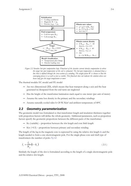
Assignment 2 2-6Initialization― Cool<strong>in</strong>g conditions― Magnetic: B -> p fe― Electric: J k,ρ 0 -> p cuF<strong>in</strong>d temperature― Coil hot-spot ϑ max― Coil average ϑ aveTarget― |ϑ target - ϑ max|≤0.05― iter ≥ max_iterResult visualization― Temperature plot (bmp)― Electric load<strong>in</strong>g (txt)Obta<strong>in</strong> new values― ρ= ρ 0(1+α(ϑ ave-ϑ 0))― p cu=0.5 ρ (J k+1) 2 Kf― iter=iter+1Obta<strong>in</strong> current density― if ϑ target - ϑ max < - 40then J k+1=J k x 0.5― if ϑ target - ϑ max > 40then J k+1=J k x 2― elseJ k+1=J k W(ϑ target - ϑ max)Figure 2.2 Iterative hot-spot computation loop. Flowchart <strong>of</strong> the iterative current density computation <strong>in</strong> wherethe target hot spot temperature <strong>of</strong> the coil is estimated. The hot-spot temperature is obta<strong>in</strong>ed from al<strong>in</strong>e that is def<strong>in</strong>ed through the cross-section <strong>of</strong> a w<strong>in</strong>d<strong>in</strong>g. The weight factor W is chosen so that theconverg<strong>in</strong>g process is as well as fast as stabile. This flowchart does not <strong>in</strong>dicate the solution when corelosses only give the target temperature or moreThe thermal models: EC model and FE model― Are two dimensional (2D), which means that <strong>heat</strong> transport along z axis and the <strong>heat</strong>generated <strong>in</strong>/dissipated from the end turns are neglected― Has the height <strong>of</strong> the <strong>transformer</strong> lam<strong>in</strong>ation stack equal to one meter (per unit <strong>of</strong> meter)― Assume the same loss density <strong>in</strong> the primary and the secondary w<strong>in</strong>d<strong>in</strong>gs― Assume naturally cooled sides h=20 W/Km 2 and ambient temperature <strong>of</strong> 40 0 C2.2 Geometry parameterizationThe geometric model was formulated so that <strong>transformer</strong> length and <strong>in</strong>sulation thickness togetherwith proportion factors will def<strong>in</strong>e the whole geometry. Additional parameters, such as proportionfactors specify the geometric proportions between the different parts <strong>of</strong> the <strong>transformer</strong>.― Ks (variable) – proportion between the slot length and core limb length― Kw (=0.5) – proportions between primary and secondary w<strong>in</strong>d<strong>in</strong>gThe length <strong>of</strong> the leg <strong>in</strong> the magnetic core is expressed by us<strong>in</strong>g the relative slot length k s and thelength needed to form a one electromagnetic pole. For the s<strong>in</strong>gle-<strong>phase</strong> core and shell type <strong>of</strong><strong>transformer</strong>s the number <strong>of</strong> poles N p =2.ll( − k )trc= 1s( 2.1 )NpSimilarly the length <strong>of</strong> the slot is formulated accord<strong>in</strong>g to the length <strong>of</strong> a s<strong>in</strong>gle electromagnetic poleand the relative slot length.AAV0090 Electrical Drives - project, TTU, 2008
![Nutman et al.2010.pdf - of / [www.ene.ttu.ee]](https://img.yumpu.com/49144272/1/190x253/nutman-et-al2010pdf-of-wwwenettuee.jpg?quality=85)
![Kogu kursuse konspekt - of / [www.ene.ttu.ee]](https://img.yumpu.com/48975288/1/184x260/kogu-kursuse-konspekt-of-wwwenettuee.jpg?quality=85)
![TEHNILINE JOONESTAMINE - of / [www.ene.ttu.ee]](https://img.yumpu.com/48482018/1/184x260/tehniline-joonestamine-of-wwwenettuee.jpg?quality=85)
![Mäeinstituudi uudiskiri nr - of / [www.ene.ttu.ee] - Tallinna ...](https://img.yumpu.com/45808782/1/190x245/maeinstituudi-uudiskiri-nr-of-wwwenettuee-tallinna-.jpg?quality=85)
![power electronics and electrical drives - of / [www.ene.ttu.ee]](https://img.yumpu.com/45392281/1/184x260/power-electronics-and-electrical-drives-of-wwwenettuee.jpg?quality=85)
![2. Loogikafunktsioonid ja loogikalülitused - of / [www.ene.ttu.ee]](https://img.yumpu.com/44975782/1/184x260/2-loogikafunktsioonid-ja-loogikala-1-4-litused-of-wwwenettuee.jpg?quality=85)
![NAFTA â MUST KULD - of / [www.ene.ttu.ee] - Tallinna Tehnikaülikool](https://img.yumpu.com/43448902/1/190x245/nafta-a-must-kuld-of-wwwenettuee-tallinna-tehnikaa-1-4-likool.jpg?quality=85)
![I OSA TUGEVUSÃPETUS - of / [www.ene.ttu.ee]](https://img.yumpu.com/43043675/1/184x260/i-osa-tugevusapetus-of-wwwenettuee.jpg?quality=85)
![TEHNILINE KOMMUNIKATSIOON - of / [www.ene.ttu.ee]](https://img.yumpu.com/42741483/1/184x260/tehniline-kommunikatsioon-of-wwwenettuee.jpg?quality=85)
![TEHNILINE KOMMUNIKATSIOON - of / [www.ene.ttu.ee]](https://img.yumpu.com/42288976/1/184x260/tehniline-kommunikatsioon-of-wwwenettuee.jpg?quality=85)
![JÃUELEKTROONIKA - of / [www.ene.ttu.ee]](https://img.yumpu.com/41203306/1/184x260/jauelektroonika-of-wwwenettuee.jpg?quality=85)
![Välitöö aruanne 3 - of / [www.ene.ttu.ee] - Tallinna Tehnikaülikool](https://img.yumpu.com/40993804/1/190x245/valitaa-aruanne-3-of-wwwenettuee-tallinna-tehnikaa-1-4-likool.jpg?quality=85)