

2 Analysis of heat transfer in a single-phase transformer
2 Analysis of heat transfer in a single-phase transformer
2 Analysis of heat transfer in a single-phase transformer
- No tags were found...

You also want an ePaper? Increase the reach of your titles
YUMPU automatically turns print PDFs into web optimized ePapers that Google loves.
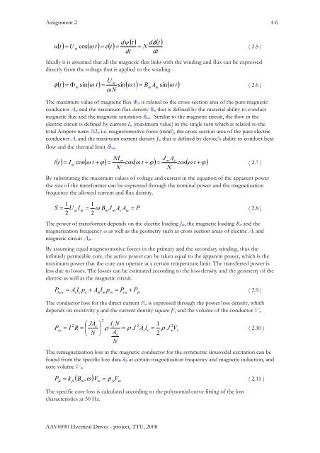
Assignment 2 4-6u() t U ( t) = e()t() t dφ( t)dψ=mcos ω = = N( 2.5 )dt dtIdeally it is assumed that all the magnetic flux l<strong>in</strong>ks with the w<strong>in</strong>d<strong>in</strong>g and flux can be expresseddirectly from the voltage that is applied to the w<strong>in</strong>d<strong>in</strong>g.φU=mm m( 2.6 )ω Nm() t Φ s<strong>in</strong> ( ω t) = s<strong>in</strong>( ω t) = B A s<strong>in</strong>( ω t)The maximum value <strong>of</strong> magnetic flux Φ m is related to the cross-section area <strong>of</strong> the pure magneticconductor A m and the maximum flux density BmB that is def<strong>in</strong>ed by the material ability to conductSimilar to the magnetic circuit, the flow <strong>in</strong> themagnetic flux and the magnetic saturation B satB .electric circuit is def<strong>in</strong>ed by current I m (maximum value) <strong>in</strong> the s<strong>in</strong>gle turn which is related to thetotal Ampere turns NI m i.e. magnetomotive force (mmf), the cross-section area <strong>of</strong> the pure electricconductor A e and the maximum current density J m that is def<strong>in</strong>ed by device’s ability to conduct <strong>heat</strong>flow and the thermal limit ϑ coil .iNIJ Acos ( 2.7 )NNmm e() t = I ( ω t + ϕ) = cos( ω t + ϕ) = cos( ω t + ϕ)mBy substitut<strong>in</strong>g the maximum values <strong>of</strong> voltage and current <strong>in</strong> the equation <strong>of</strong> the apparent powerthe size <strong>of</strong> the <strong>transformer</strong> can be expressed through the nom<strong>in</strong>al power and the magnetizationfrequency the allowed current and flux density.1 1S = UmIm= ω BmJmAeAm= P2 2( 2.8 )The power <strong>of</strong> <strong>transformer</strong> depends on the electric load<strong>in</strong>g J m , the magnetic load<strong>in</strong>g BmB and themagnetization frequency ω as well as the geometry such as cross section areas <strong>of</strong> electric A e andmagnetic circuit A m .By assum<strong>in</strong>g equal magnetomotive forces <strong>in</strong> the primary and the secondary w<strong>in</strong>d<strong>in</strong>g, thus the<strong>in</strong>f<strong>in</strong>itely permeable core, the active power can be taken equal to the apparent power, which is themaximum power that the core can operate at a certa<strong>in</strong> temperature limit. The <strong>transfer</strong>red power isless due to losses. The losses can be estimated accord<strong>in</strong>g to the loss density and the geometry <strong>of</strong> theelectric as well as the magnetic circuit.P = A l p + A l p = P + P( 2.9 )losse eem mmcufeThe conductor loss for the direct current P cu is expressed through the power loss density, whichdepends on resistivity ρ and the current density square J 2 , and the volume <strong>of</strong> the conductor V e .22 ⎛ JAe⎞ leN2 1 2cu= I R = ⎜ ρ = ρ J Aele = ρ JmVe( 2.10 )N Ae2P⎝⎟⎠NThe remagnetization loss <strong>in</strong> the magnetic conductor for the symmetric s<strong>in</strong>usoidal excitation can befound from the specific loss data k fe at certa<strong>in</strong> magnetization frequency and magnetic <strong>in</strong>duction, andcore volume V mfefe( Bm) VmpfeVmP = k , ω =( 2.11 )The specific core loss is calculated accord<strong>in</strong>g to the polynomial curve fitt<strong>in</strong>g <strong>of</strong> the losscharacteristics at 50 Hz.AAV0090 Electrical Drives - project, TTU, 2008
![Nutman et al.2010.pdf - of / [www.ene.ttu.ee]](https://img.yumpu.com/49144272/1/190x253/nutman-et-al2010pdf-of-wwwenettuee.jpg?quality=85)
![Kogu kursuse konspekt - of / [www.ene.ttu.ee]](https://img.yumpu.com/48975288/1/184x260/kogu-kursuse-konspekt-of-wwwenettuee.jpg?quality=85)
![TEHNILINE JOONESTAMINE - of / [www.ene.ttu.ee]](https://img.yumpu.com/48482018/1/184x260/tehniline-joonestamine-of-wwwenettuee.jpg?quality=85)
![Mäeinstituudi uudiskiri nr - of / [www.ene.ttu.ee] - Tallinna ...](https://img.yumpu.com/45808782/1/190x245/maeinstituudi-uudiskiri-nr-of-wwwenettuee-tallinna-.jpg?quality=85)
![power electronics and electrical drives - of / [www.ene.ttu.ee]](https://img.yumpu.com/45392281/1/184x260/power-electronics-and-electrical-drives-of-wwwenettuee.jpg?quality=85)
![2. Loogikafunktsioonid ja loogikalülitused - of / [www.ene.ttu.ee]](https://img.yumpu.com/44975782/1/184x260/2-loogikafunktsioonid-ja-loogikala-1-4-litused-of-wwwenettuee.jpg?quality=85)
![NAFTA â MUST KULD - of / [www.ene.ttu.ee] - Tallinna Tehnikaülikool](https://img.yumpu.com/43448902/1/190x245/nafta-a-must-kuld-of-wwwenettuee-tallinna-tehnikaa-1-4-likool.jpg?quality=85)
![I OSA TUGEVUSÃPETUS - of / [www.ene.ttu.ee]](https://img.yumpu.com/43043675/1/184x260/i-osa-tugevusapetus-of-wwwenettuee.jpg?quality=85)
![TEHNILINE KOMMUNIKATSIOON - of / [www.ene.ttu.ee]](https://img.yumpu.com/42741483/1/184x260/tehniline-kommunikatsioon-of-wwwenettuee.jpg?quality=85)
![TEHNILINE KOMMUNIKATSIOON - of / [www.ene.ttu.ee]](https://img.yumpu.com/42288976/1/184x260/tehniline-kommunikatsioon-of-wwwenettuee.jpg?quality=85)
![JÃUELEKTROONIKA - of / [www.ene.ttu.ee]](https://img.yumpu.com/41203306/1/184x260/jauelektroonika-of-wwwenettuee.jpg?quality=85)
![Välitöö aruanne 3 - of / [www.ene.ttu.ee] - Tallinna Tehnikaülikool](https://img.yumpu.com/40993804/1/190x245/valitaa-aruanne-3-of-wwwenettuee-tallinna-tehnikaa-1-4-likool.jpg?quality=85)