

2 Analysis of heat transfer in a single-phase transformer
2 Analysis of heat transfer in a single-phase transformer
2 Analysis of heat transfer in a single-phase transformer
- No tags were found...

Create successful ePaper yourself
Turn your PDF publications into a flip-book with our unique Google optimized e-Paper software.
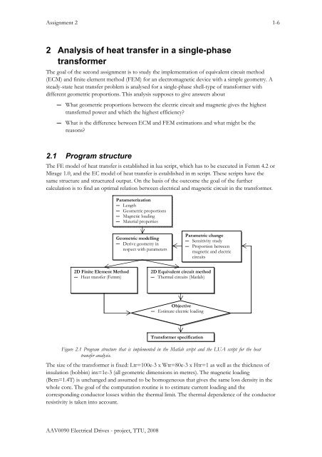
Assignment 2 2-6Initialization― Cool<strong>in</strong>g conditions― Magnetic: B -> p fe― Electric: J k,ρ 0 -> p cuF<strong>in</strong>d temperature― Coil hot-spot ϑ max― Coil average ϑ aveTarget― |ϑ target - ϑ max|≤0.05― iter ≥ max_iterResult visualization― Temperature plot (bmp)― Electric load<strong>in</strong>g (txt)Obta<strong>in</strong> new values― ρ= ρ 0(1+α(ϑ ave-ϑ 0))― p cu=0.5 ρ (J k+1) 2 Kf― iter=iter+1Obta<strong>in</strong> current density― if ϑ target - ϑ max < - 40then J k+1=J k x 0.5― if ϑ target - ϑ max > 40then J k+1=J k x 2― elseJ k+1=J k W(ϑ target - ϑ max)Figure 2.2 Iterative hot-spot computation loop. Flowchart <strong>of</strong> the iterative current density computation <strong>in</strong> wherethe target hot spot temperature <strong>of</strong> the coil is estimated. The hot-spot temperature is obta<strong>in</strong>ed from al<strong>in</strong>e that is def<strong>in</strong>ed through the cross-section <strong>of</strong> a w<strong>in</strong>d<strong>in</strong>g. The weight factor W is chosen so that theconverg<strong>in</strong>g process is as well as fast as stabile. This flowchart does not <strong>in</strong>dicate the solution when corelosses only give the target temperature or moreThe thermal models: EC model and FE model― Are two dimensional (2D), which means that <strong>heat</strong> transport along z axis and the <strong>heat</strong>generated <strong>in</strong>/dissipated from the end turns are neglected― Has the height <strong>of</strong> the <strong>transformer</strong> lam<strong>in</strong>ation stack equal to one meter (per unit <strong>of</strong> meter)― Assume the same loss density <strong>in</strong> the primary and the secondary w<strong>in</strong>d<strong>in</strong>gs― Assume naturally cooled sides h=20 W/Km 2 and ambient temperature <strong>of</strong> 40 0 C2.2 Geometry parameterizationThe geometric model was formulated so that <strong>transformer</strong> length and <strong>in</strong>sulation thickness togetherwith proportion factors will def<strong>in</strong>e the whole geometry. Additional parameters, such as proportionfactors specify the geometric proportions between the different parts <strong>of</strong> the <strong>transformer</strong>.― Ks (variable) – proportion between the slot length and core limb length― Kw (=0.5) – proportions between primary and secondary w<strong>in</strong>d<strong>in</strong>gThe length <strong>of</strong> the leg <strong>in</strong> the magnetic core is expressed by us<strong>in</strong>g the relative slot length k s and thelength needed to form a one electromagnetic pole. For the s<strong>in</strong>gle-<strong>phase</strong> core and shell type <strong>of</strong><strong>transformer</strong>s the number <strong>of</strong> poles N p =2.ll( − k )trc= 1s( 2.1 )NpSimilarly the length <strong>of</strong> the slot is formulated accord<strong>in</strong>g to the length <strong>of</strong> a s<strong>in</strong>gle electromagnetic poleand the relative slot length.AAV0090 Electrical Drives - project, TTU, 2008
Assignment 2 3-6ltrls= ks( 2.2 )NpThe width <strong>of</strong> the slot is given by the total width <strong>of</strong> the <strong>transformer</strong> w tr m<strong>in</strong>us the width <strong>of</strong> themagnetic core yokes. The width <strong>of</strong> the magnetic back-core (yoke) equals to the length <strong>of</strong> themagnetic leg-core. The slot width for the shell type <strong>of</strong> <strong>transformer</strong> isws= w − l( 2.3 )trcFigure 2.3 The geometry parameterization <strong>of</strong> the shell type <strong>of</strong> <strong>transformer</strong>. The upper figure shows the magneticflux flow plane (xy-plane) and the lower figure shows the electric current flow plane (xz-plane).2.3 Size equationsThe size <strong>of</strong> <strong>transformer</strong> is related to the power <strong>of</strong> the electromagnetic device and the allowed ‘flow’densities such as current density, flux density and the loss density. In an ideal <strong>transformer</strong> themagnetic coupl<strong>in</strong>g between the w<strong>in</strong>d<strong>in</strong>gs is perfect. There is the same core flux φ(t) that l<strong>in</strong>ks eachturn <strong>of</strong> each w<strong>in</strong>d<strong>in</strong>g. Apparent power <strong>of</strong> an ideal lossless <strong>transformer</strong> is expressed asS 1=2 U I m m( 2.4 )here is assumed s<strong>in</strong>usoidal variation <strong>of</strong> voltage and current and <strong>in</strong>stead <strong>of</strong> rms values the peakvalues has been used <strong>in</strong>stead. Consider<strong>in</strong>g the lossless electromagnetic circuit the voltage <strong>of</strong> theelectric circuit can be directly l<strong>in</strong>ked to the <strong>in</strong>duced back electromotive force (emf) and themagnetic flux <strong>in</strong> the magnetic circuit.AAV0090 Electrical Drives - project, TTU, 2008
Assignment 2 4-6u() t U ( t) = e()t() t dφ( t)dψ=mcos ω = = N( 2.5 )dt dtIdeally it is assumed that all the magnetic flux l<strong>in</strong>ks with the w<strong>in</strong>d<strong>in</strong>g and flux can be expresseddirectly from the voltage that is applied to the w<strong>in</strong>d<strong>in</strong>g.φU=mm m( 2.6 )ω Nm() t Φ s<strong>in</strong> ( ω t) = s<strong>in</strong>( ω t) = B A s<strong>in</strong>( ω t)The maximum value <strong>of</strong> magnetic flux Φ m is related to the cross-section area <strong>of</strong> the pure magneticconductor A m and the maximum flux density BmB that is def<strong>in</strong>ed by the material ability to conductSimilar to the magnetic circuit, the flow <strong>in</strong> themagnetic flux and the magnetic saturation B satB .electric circuit is def<strong>in</strong>ed by current I m (maximum value) <strong>in</strong> the s<strong>in</strong>gle turn which is related to thetotal Ampere turns NI m i.e. magnetomotive force (mmf), the cross-section area <strong>of</strong> the pure electricconductor A e and the maximum current density J m that is def<strong>in</strong>ed by device’s ability to conduct <strong>heat</strong>flow and the thermal limit ϑ coil .iNIJ Acos ( 2.7 )NNmm e() t = I ( ω t + ϕ) = cos( ω t + ϕ) = cos( ω t + ϕ)mBy substitut<strong>in</strong>g the maximum values <strong>of</strong> voltage and current <strong>in</strong> the equation <strong>of</strong> the apparent powerthe size <strong>of</strong> the <strong>transformer</strong> can be expressed through the nom<strong>in</strong>al power and the magnetizationfrequency the allowed current and flux density.1 1S = UmIm= ω BmJmAeAm= P2 2( 2.8 )The power <strong>of</strong> <strong>transformer</strong> depends on the electric load<strong>in</strong>g J m , the magnetic load<strong>in</strong>g BmB and themagnetization frequency ω as well as the geometry such as cross section areas <strong>of</strong> electric A e andmagnetic circuit A m .By assum<strong>in</strong>g equal magnetomotive forces <strong>in</strong> the primary and the secondary w<strong>in</strong>d<strong>in</strong>g, thus the<strong>in</strong>f<strong>in</strong>itely permeable core, the active power can be taken equal to the apparent power, which is themaximum power that the core can operate at a certa<strong>in</strong> temperature limit. The <strong>transfer</strong>red power isless due to losses. The losses can be estimated accord<strong>in</strong>g to the loss density and the geometry <strong>of</strong> theelectric as well as the magnetic circuit.P = A l p + A l p = P + P( 2.9 )losse eem mmcufeThe conductor loss for the direct current P cu is expressed through the power loss density, whichdepends on resistivity ρ and the current density square J 2 , and the volume <strong>of</strong> the conductor V e .22 ⎛ JAe⎞ leN2 1 2cu= I R = ⎜ ρ = ρ J Aele = ρ JmVe( 2.10 )N Ae2P⎝⎟⎠NThe remagnetization loss <strong>in</strong> the magnetic conductor for the symmetric s<strong>in</strong>usoidal excitation can befound from the specific loss data k fe at certa<strong>in</strong> magnetization frequency and magnetic <strong>in</strong>duction, andcore volume V mfefe( Bm) VmpfeVmP = k , ω =( 2.11 )The specific core loss is calculated accord<strong>in</strong>g to the polynomial curve fitt<strong>in</strong>g <strong>of</strong> the losscharacteristics at 50 Hz.AAV0090 Electrical Drives - project, TTU, 2008
Assignment 2 5-62( 2.5517B−1.2936B+ 0.8143) ⋅ 7700p ( 2.12 )fe=mmF<strong>in</strong>ally, the efficiency can be found from the <strong>in</strong>put power and the loss power.P − Plossη =( 2.13 )PLua-script as well as m-script EMK_task_1.lua and EMK_task_1.m, calculate hot spottemperature <strong>of</strong> the w<strong>in</strong>d<strong>in</strong>g ϑmax, core temperature ϑcc, the specific copper loss pcu, maximumcurrent density Jcm and so on as a function <strong>of</strong> proportion. Some <strong>of</strong> the variables are not estimatedwith the thermal equivalent circuit.for kh = 1,9,1 doendx[m]ϑmax[°C]ϑave[°C]pcu[W/m 3 ]Jcm[A/m 2 ]Aw[m 2 ]ϑcc[°C]The result <strong>of</strong> the computations is written <strong>in</strong>to file tmp_<strong>heat</strong>_fem.txt and tmp_<strong>heat</strong>_emc.txt.2.4 EC modelEquivalent circuit model has been given <strong>in</strong> EMK_task_1.m.The thermal conductivity network consists <strong>of</strong> 11 elements that represent the <strong>heat</strong> dissipation <strong>in</strong> thesymmetric part <strong>of</strong> the <strong>transformer</strong>. The cool<strong>in</strong>g condition through the natural convection is taken<strong>in</strong>to account <strong>in</strong> the elements 4 and 11. Nodal network represents the temperature over 9 nodepo<strong>in</strong>ts. The copper losses are applied <strong>in</strong>to node 2 and 3, the core losses to node 1 and the ambient(reference) temperature is described <strong>in</strong> nodes 5 and 9.9iter[-]1165876981012141110131211512167233445Figure 2.4 The thermal equivalent circuit <strong>of</strong> the s<strong>in</strong>gle-<strong>phase</strong> shell-type <strong>transformer</strong>. Thermal elements <strong>in</strong> theend-turns are excluded <strong>in</strong> order to make EC model and FE models comparable.AAV0090 Electrical Drives - project, TTU, 2008
Assignment 2 6-6Code that shows the formulation <strong>of</strong> thermal equivalent circuit and the elements <strong>in</strong> the circuit% thermal equivalent circuit - topology matrix% [element(1) node(n) node(m) thermal conductivity]Tec = [ 1 1 2 0.5*h_c * 0.5*w_s / (0.5*l_c/tc_fe+<strong>in</strong>s/tc_<strong>in</strong>s+0.5*l_w1/tc_w<strong>in</strong>);2 2 3 0.5*h_c * 0.5*w_s / (0.5*l_w1/tc_w<strong>in</strong>+<strong>in</strong>s/tc_<strong>in</strong>s+0.5*l_w2/tc_w<strong>in</strong>);3 3 4 0.5*h_c * 0.5*w_s / (0.5*l_w2/tc_w<strong>in</strong>+<strong>in</strong>s/tc_<strong>in</strong>s+0.25*l_c/tc_fe);4 4 5 0.5*h_c * 0.5*w_s / (0.25*l_c/tc_fe+1/Aconv);5 1 6 0.5*h_c * 0.5*l_c / ((0.5*w_s+0.25*l_c)/tc_fe);6 2 7 0.5*h_c * l_w1 / ((0.5*w_s-<strong>in</strong>s)/tc_w<strong>in</strong>+<strong>in</strong>s/tc_<strong>in</strong>s+0.25*l_c/tc_fe);7 3 8 0.5*h_c * l_w2 / ((0.5*w_s-<strong>in</strong>s)/tc_w<strong>in</strong>+<strong>in</strong>s/tc_<strong>in</strong>s+0.25*l_c/tc_fe);8 6 7 0.5*h_c * 0.25*l_c / ((0.5*l_c+<strong>in</strong>s+0.5*l_w1)/tc_fe);9 7 8 0.5*h_c * 0.25*l_c / ((0.5*l_w1+<strong>in</strong>s+0.5*l_w2)/tc_fe);10 8 4 0.5*h_c * 0.5*l_c / ((0.5*w_s+0.5*l_c)/tc_fe);11 6 9 0.5*h_c * 0.5*Ltr / ((0.25*l_c)/tc_fe+1/Aconv);];2.5 FE modelF<strong>in</strong>ite element model has been given <strong>in</strong> EMK_task_1.lua.The xy-plane cross-section <strong>of</strong> a shell type <strong>of</strong> <strong>transformer</strong> is the base geometry for the <strong>heat</strong> <strong>transfer</strong>analysis. Notice that the loop calculations are commented out and <strong>in</strong>itially the relative slot open<strong>in</strong>gis selected 50%.2.6 AssignmentBased on the outcome from FE and EC model (that takes at least 5 m<strong>in</strong>utes)― Show Jcm=f(ks) for these deferent models― Calculate a <strong>transfer</strong>red power P=f(ks) for these deferent models― Calculate copper and core losses and the sum <strong>of</strong> these losses Ploss=f(ks)― Estimate the efficiency for these deferent modelsAnalyze the outcome <strong>of</strong> the FE analysis and if necessary <strong>in</strong>troduce additional calculations <strong>in</strong> orderto evaluate the thermal conductance shown below:a)ϑ cuQ cuG th1ϑ ambc)ϑ cu1Q cu1G th1ϑ ambb)G th3ϑ cuQ cuG th1ϑ ambG th6ϑ cu2Q cu2G th4G th2G th5Q feϑ feG th2ϑ feQ feG th3Carry out this study for an optimal <strong>transformer</strong> and as far you are able i.e. start from circuit a,cont<strong>in</strong>ue with b and if you are able then also circuit c.AAV0090 Electrical Drives - project, TTU, 2008

![Nutman et al.2010.pdf - of / [www.ene.ttu.ee]](https://img.yumpu.com/49144272/1/190x253/nutman-et-al2010pdf-of-wwwenettuee.jpg?quality=85)
![Kogu kursuse konspekt - of / [www.ene.ttu.ee]](https://img.yumpu.com/48975288/1/184x260/kogu-kursuse-konspekt-of-wwwenettuee.jpg?quality=85)
![TEHNILINE JOONESTAMINE - of / [www.ene.ttu.ee]](https://img.yumpu.com/48482018/1/184x260/tehniline-joonestamine-of-wwwenettuee.jpg?quality=85)
![Mäeinstituudi uudiskiri nr - of / [www.ene.ttu.ee] - Tallinna ...](https://img.yumpu.com/45808782/1/190x245/maeinstituudi-uudiskiri-nr-of-wwwenettuee-tallinna-.jpg?quality=85)
![power electronics and electrical drives - of / [www.ene.ttu.ee]](https://img.yumpu.com/45392281/1/184x260/power-electronics-and-electrical-drives-of-wwwenettuee.jpg?quality=85)
![2. Loogikafunktsioonid ja loogikalülitused - of / [www.ene.ttu.ee]](https://img.yumpu.com/44975782/1/184x260/2-loogikafunktsioonid-ja-loogikala-1-4-litused-of-wwwenettuee.jpg?quality=85)
![NAFTA â MUST KULD - of / [www.ene.ttu.ee] - Tallinna Tehnikaülikool](https://img.yumpu.com/43448902/1/190x245/nafta-a-must-kuld-of-wwwenettuee-tallinna-tehnikaa-1-4-likool.jpg?quality=85)
![I OSA TUGEVUSÃPETUS - of / [www.ene.ttu.ee]](https://img.yumpu.com/43043675/1/184x260/i-osa-tugevusapetus-of-wwwenettuee.jpg?quality=85)
![TEHNILINE KOMMUNIKATSIOON - of / [www.ene.ttu.ee]](https://img.yumpu.com/42741483/1/184x260/tehniline-kommunikatsioon-of-wwwenettuee.jpg?quality=85)
![TEHNILINE KOMMUNIKATSIOON - of / [www.ene.ttu.ee]](https://img.yumpu.com/42288976/1/184x260/tehniline-kommunikatsioon-of-wwwenettuee.jpg?quality=85)
![JÃUELEKTROONIKA - of / [www.ene.ttu.ee]](https://img.yumpu.com/41203306/1/184x260/jauelektroonika-of-wwwenettuee.jpg?quality=85)
![Välitöö aruanne 3 - of / [www.ene.ttu.ee] - Tallinna Tehnikaülikool](https://img.yumpu.com/40993804/1/190x245/valitaa-aruanne-3-of-wwwenettuee-tallinna-tehnikaa-1-4-likool.jpg?quality=85)