MOUNTING & DEMOUNTING SAFETY INFORMATION - Titan
MOUNTING & DEMOUNTING SAFETY INFORMATION - Titan
MOUNTING & DEMOUNTING SAFETY INFORMATION - Titan
- No tags were found...

Create successful ePaper yourself
Turn your PDF publications into a flip-book with our unique Google optimized e-Paper software.
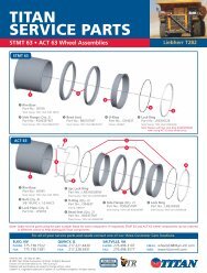
1.800.USA.BEAR www.titanstore.com <strong>Titan</strong> Tire CorporationSafety InformationDemounting Tires on <strong>Titan</strong> Assemblies5-Piece Rim AssembliesTools Required: hydraulic demountingtool and two straight tire irons, screwdriver,piece of wire.The task of servicing tires andwheels can be extremely dangerousand should be performed by trainedpersonnel only, using the correct toolsand following specific procedures. If youhave any doubt about the correct, safemethod of performing any step in the demounting,mounting, or inflating processSTOP! Seek assistance from a qualifiedperson.Always completely deflate tire(both tires of a dual assembly)by removing valve core(s) fromvalve(s) before attempting any demountingoperation. Check the valve stem byrunning a piece of wire through the stemto make sure it is not plugged. Removedriving key if present. See page S-24.1. Place the assembly gutter side up onblocks.place. However, these items must beremoved before removal of bead seatbands and flanges in step 7).Keep fingers clear of pinch points.Do not release your grip on thetire irons, as they may springback.3. Remove the “O” ring by prying thebead seat band back and inserting a prybar or screwdriver under the “O” ringand pulling it from the groove. It is goodpractice to cut and discard the “O” ringand replace with a new “O” ring.Keep fingers clear of pinch points.under pressure. In some cases, thepressure foot may have to be removedto ensure a good hold. Activate thehydraulic pump and apply pressure. Ifnecessary, release pressure and readjustthe ram adjusting screw. Depressflange about 1⁄2”-3⁄4” and place a nut orsimilar object between the flange andthe lip of the bead seat band by laying iton the rim flange and sliding it into positionwith a screwdriver.Keep fingers clear of pinch points.Always stand to one side of thetool and hold it with one hand.This allows control should the tool notseat properly and fly off.7. Remove outer flange (ref. p. S-21)using a hoist or pry bars.Always stand clear when usingmechanical lifting devices.8. Turn assembly over and repeat tirebead unseating procedure on the backside. (Steps 4 & 5)9. Lift rim base from tire using hoist.2. Remove the lock ring, using two tireirons (NOTE: If this is not possible, thetire bead may be unseated as shown instep 4 with the lock ring and “O” ring in4. Place hook of the hydraulic demountingtool into one of the pry bar pockets.A continuous lip is provided on somebases. Adjust the ram adjusting screw toenable the tool to remain vertical when5. Release the pressure and moveabout 2 feet around the rim or to thenext pocket for the second bite. Continuethe procedure until the tire bead isunseated.Do not use tool in the vicinity ofthe butt weld area of the bead seatband, the flanges, or rim base.6. Remove bead seat band using hoistor pry bars.Keep fingers clear of pinch points.10. Remove inner flange. (ref. p. S-21)In some cases it may be advantageousto use a more powerful hydraulicdemounting tool with a longer stroke.However, caution must be used to avoidbending the flange or breaking the buttweld. Follow procedure outlined in step4.If the flange or butt weld are damaged,destroy the parts, discard,and replace with good parts.S-28