MC-Balance User Manual 4.0.UK.00
MC-Balance User Manual 4.0.UK.00
MC-Balance User Manual 4.0.UK.00
- No tags were found...

You also want an ePaper? Increase the reach of your titles
YUMPU automatically turns print PDFs into web optimized ePapers that Google loves.
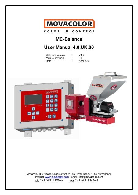
<strong>MC</strong>-<strong>Balance</strong><strong>User</strong> <strong>Manual</strong> <strong>4.0.UK.00</strong>Software version : V4.0<strong>Manual</strong> revision : 0.0Date : April 2008Movacolor B.V • Koperslagersstraat 31• 8601 WL Sneek • The NetherlandsInternet: www.movacolor.com • Email: info@movacolor.com+ 31 (0) 515 570020 + 31 (0) 515 570021
INDEX1. Introduction ______________________________________________________________________________________________11.1 Symbols_______________________________________________________________________________________________11.2 Terms ________________________________________________________________________________________________12. General information________________________________________________________________________________________22.1 Safety ________________________________________________________________________________________________22.2 Certification ____________________________________________________________________________________________22.3 Operating environmental conditions _________________________________________________________________________23. Overview Dosing unit ______________________________________________________________________________________33.1 <strong>MC</strong>-<strong>Balance</strong> Component overview __________________________________________________________________________33.2 Weighing frame _________________________________________________________________________________________43.3 Motor and dosing system _________________________________________________________________________________44. Metering principle _________________________________________________________________________________________55. Dosing systems / Capacities ________________________________________________________________________________66. Installation _______________________________________________________________________________________________86.1 Transport ______________________________________________________________________________________________86.2 Receipt _______________________________________________________________________________________________86.3 Mechanical Installation ___________________________________________________________________________________86.4 Changing from Dosing cylinder to Feed screw _________________________________________________________________96.5 Electrical installation ____________________________________________________________________________________107. Operation _______________________________________________________________________________________________127.1 Navigation ____________________________________________________________________________________________127.2 Start up & Login________________________________________________________________________________________137.3 Keyboard lock _________________________________________________________________________________________147.4 Configuration __________________________________________________________________________________________157.5 Loadcell calibration _____________________________________________________________________________________217.6 Material Pre-calibration __________________________________________________________________________________227.7 Production ____________________________________________________________________________________________247.8 Auto/<strong>Manual</strong> regulation mode & Save data function ____________________________________________________________277.9 Production JOB ________________________________________________________________________________________287.10 Filling the hopper. _____________________________________________________________________________________297.11 Consumption _________________________________________________________________________________________337.12 Alarms ______________________________________________________________________________________________347.13 Files________________________________________________________________________________________________367.14 Event LOG___________________________________________________________________________________________378. System performance ______________________________________________________________________________________388.1 Reset regulation _______________________________________________________________________________________389. Trouble shooting _________________________________________________________________________________________39APPENDIX A: <strong>MC</strong>-Bal. Print view __________________________________________________________________________40APPENDIX B: <strong>MC</strong>-Bal. Wiring Diagram _____________________________________________________________________41APPENDIX C: <strong>MC</strong>-Bal. Technical Specifications ______________________________________________________________42APPENDIX D: <strong>MC</strong>-Bal. Drawings General Dimensions_________________________________________________________43APPENDIX E: <strong>MC</strong>-Bal. Decl. of Conformity __________________________________________________________________47
1. IntroductionThank you for purchasing a Movacolor metering device. This manual is addressed to operatorsand qualified technicians taking care of the metering of dry additives to ensure correct use of theMovacolor dosing unit.i IMPORTANT NOTE: THIS MANUAL MUST BE READ BEFORE INSTALLING THE DOSINGUNIT. KEEP THIS MANUAL IN A PLACE ACCESSIBLE FOR ALL OPERATORS.1.1 SymbolsiImportant note1.2 TermsAttention; safety regulations for the operatorOperator:Qualified Technician:A person charged to operate, adjust, maintain and clean the machine.A specialized, suitable trained person authorized to execute theinstallation, non-routine maintenance, or repairs requiring specialknowledge of the machine and how it operates.1<strong>MC</strong>-<strong>Balance</strong> manual
2. General information2.1 SafetyThe equipment is only designed and may only be used for the dosing of dry additives.Any use that is not in conformity with the instructions is considered improper and as suchfrees the manufacturer from any liability regarding damage to things and/or persons.Before switching on the unit for the first time, ensure that the mains power voltageapplied is between 80 and 260Vac.Always switch off the Movacolor control cabinet and disconnect the mains power plug fromelectrical power before performing maintenance.Ensure that all parts are securely fixed to the extruder or injection molding machine.Dangerous voltages are present inside the control cabinet for up to 2 minutes after it hasbeen switched off.2.2 CertificationThe Movacolor dosing unit is designed and produced in conformity with the following Europeanregulations:• standards for machinery (health, safety, environment)• E<strong>MC</strong> (electromagnetic compatibility)• VEM (safety electric material)• 98/37/EC, Annex 1(See the declaration of conformity, Appendix E)2.3 Operating environmental conditions• The unit must be protected against weather conditions• Operating temperature -20 to +70 degr. C.• Protection class: IP-502<strong>MC</strong>-<strong>Balance</strong> manual
3. Overview Dosing unit3.1 <strong>MC</strong>-<strong>Balance</strong> Component overview1051 2.3 46.7 891 Stepper motor2 Dosing system (Dosing cylinder)3 Hopper 6 ltr4 Curled knob M10x405 Standard NST40 Neckpiece6 Material discharge slide (in closed position)7 <strong>MC</strong>-<strong>Balance</strong> Load frame8 OPTIONAL Slide frame9 Slide locking bolt(locking the slide-out position)Only supplied together with the optional slide mechanism10 Slide locking bar(locking the slide-in position)Only supplied together with the optional slide mechanism3<strong>MC</strong>-<strong>Balance</strong> manual
3.2 Weighing frameTransport protectionSafety bolts (total of 4)Hopper loader tube support<strong>Balance</strong> frameThe black part is the weighing frame.Do not touch this weighing frame (and dosing unit) while dosing.It will have influence on the dosing.Do not touch the safety bolts under the weighing platform. These are for overload protection.There must be some space between de safety bolts and the frame.3.3 Motor and dosing systemThere are mainly two dosing systems, the dosing cylinder and the feed screw.(for more information see chapter 5)The serial number of the motor can be found on thebackside of the motor.Motor axle:The motor shaft is equipped with one flat side whichfits exact in shaft of the dosing cylinder.To connect the dosing cylinder just put it on themotor axle while turning it to find the flat side, thanpress the dosing cylinder completely backwards.4<strong>MC</strong>-<strong>Balance</strong> manual
4. Metering principleThe Dosing Cylinder® of Movacolor combined with a very precise adjustable stepper motorensures that the additive output is accurate and regular. The neckpiece (a mixing chamber) isdesigned to blend the main material and the additive homogeneously. Movacolor has on stock alarge range of machine neckpieces that usually make a prefect fit to the injection molding machineor extruder. The most common mounting of the neckpiece is between the production machine andthe hopper. In the figure below a cut through of the NST40 neckpiece can be seen.Standard neckpieceDuring operation, the virgin material runs fromthe machine hopper through the neckpieceinto the machine. Inside the neckpiece theVirgin material flow is divided into twostreamsby the cover plate. In the space below thecover plate, the rotating cylinder is dosingadditive.1243Additive is added directly into the center ofthe virgin material flow, just before it entersthe production machine. This is a greatadvantage over metering devices that usebatch pre-mixing because pre-mixing canactually cause material separation.Separation of materials results in an irregularadditive flow into the production machine.56Fig. 31. Color 2. Virgin material 3. Neckpiece 4. Dosing cylinder4. Cover plate 5. Mixing zone 6. To production machine5<strong>MC</strong>-<strong>Balance</strong> manual
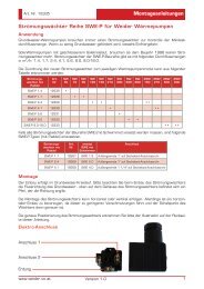
5. Dosing systems / CapacitiesDepending on the application a different dosing system might be needed.Use the following table to determine roughly the best system for the application. For more detailedinformation please contact your agent or Movacolor.Dosing system Granular Powder Accuracy Dosing capacity Dosing capacitymaterials MaterialsGram/sec. Kg/hourGLX YES YES ++ 0,02 to 1,6* 0,07 to 5,8*GX YES YES + 0,2 to 5,0* 0,72 to 18,0*HX NO YES ++ 0,01 to 1,6** 0,04 to 5,8**A-20Feed screwA-30Feed screw ***YES YES +/- 0,5 to 20* 1,8 to 72*YES YES +/- 2 to 50* 7,2 to 180*Note *Note **Note ***measured with normal granular masterbatch 0,8 kg/dm3.measured with free flowing powder 0,65 kg/dm3.only available with high torque (4,5 Amp) stepper motorFront side viewGLXGXHXA20LT A20HT A30HTBack side viewWhich type of dosing system do I need with which neckpiece?TYPE CODE FOR STANDARD NECKPIECE CODE FOR WATERCOOLED NECKPIECEGLX GLX GLXCGX GX GXCHX HX HXCA20LT A20 A20CA20HT A20HT A20HTCA30HT A30 A30C6<strong>MC</strong>-<strong>Balance</strong> manual
All Movacolor dosing units are standard equipped with the stepper motor 2A (LT), in case of usingthe feed screw A30 the stepper motor 4,5A (HT) will be supplied. Also a screw A20 can beconnected to the HT motor.Stepper motor 2A(LT)Stepper motor 4,5A(HT)i Do not select the HT motor if LT motor is connected. This will damage the motor.If LT motor is selected and HT motor is connected there will be less motor torque and this caninfluence the dosing.The controller of the dosing unit makes a distinction between two groups of materials, normalgranules and micro granules. To determine the kind of material in your application use thedescription below.Material typesNormal Granules:(NG)øØ < 4 mm L < 4 mm *LMicro / Mini Granules:(MG)øThe term Micro/Mini Granules alsoincludes free flowing powder.Ø < ø2,5 mm L < 3 mm *L* For other sizes contact Movacolor.The actual capacity of the dosing system depends on:• The volume weight of the material (bulk density)• The specific weight of the material (specific density)• The granular shape of the material• The granule size• The surface structure of the materialGranular material can be normal or micro. The granular material and powder material has to befree flowing, non-static and not sticky.7<strong>MC</strong>-<strong>Balance</strong> manual
BALL BEARINGi For cleaning of the ball bearing use a dry piece of textile or a smooth dry toothbrush to removethe dust or moisture and foreign particles that stick.i Following points have effect on the lifetime of the ball bearing:o Abrasive materialso Temperatureo Dusty / fine powder materials6.5 Electrical installationThe <strong>MC</strong>-<strong>Balance</strong> controller is standard equipped with 3 connections:• Mains power cablei Before switching on the unit for the first time, ensure the mains power voltage beingapplied is between 80 and 260Vac.• Input cable• Motor cablei Be aware that the cables will not be influenced by external circumstances as electromagneticfields!i Mount the controller on a place which is vibrations free and not hot!.Optional are:• Alarm flash light, complete with cable• Compressed air solenoid valve complete with cable (for automatic hopper loader)10<strong>MC</strong>-<strong>Balance</strong> manual
APPENDIX A SHOWS THE PRINT VIEW WHICH WILL BE EXPLAINED BELOW1) PROCESSOR BOARDThe processor board is the heart of the controller.This board must be fixed securely on the mainboard.There’s also a label on it with the Mac-address. This is the ID of the networkcard.This address can also be seen in the startup screen.2) EXTERNAL TERMINAL CONNECTIONThis connector will be used when using an external terminal (Shielded cable max. 10 meter)3) CONNECTION TO PC OR NETWORKThis connection (Ethernet) will be used when using a PC or network.Max. length of the UTP network cable, type RJ45 (Cat. 5) is 100 meter between 2network points.4) INPUTSStart inputThe <strong>MC</strong>-<strong>Balance</strong> needs an input signal from the production machine in order to operate.Three different input signals can be used to control the <strong>MC</strong>-<strong>Balance</strong>:• Potential free start input.• Potential (24 Vdc) start input• Tacho (0-30 Vdc) start input5) MOTORThe <strong>MC</strong>-<strong>Balance</strong> can control 2 motor types:• LT (low torque) standard motor for normal dosing• HT (high torque) motor for high output dosing(See chapter 5 for more details and wiring diagram for electrical connections, appendix C)6) OUTPUTSThe <strong>MC</strong>-<strong>Balance</strong> has following outputs available:• [clamp 24-25] Valve output for hopper loader, (Solid state 24VDC/0.5 A)• [clamp 22-23] Warning output (Solid state 24VDC/0.5 A)• [clamp 26-27] Potential free relay (normally open) output for Alarm (max. 230Vac/30Vdc, 5A)• [clamp 28-29] Potential free relay (normally open) output for Running contact(max. 230Vac/30Vdc, 5A). This contact will be used to show that the motor is running.The maximum total output power may be 12 Watt (Valve output + alarm output together max. 0,5A)(See wiring diagram appendix C for electrical connections)7) POWER SUPPLYThe <strong>MC</strong>-<strong>Balance</strong> will operate with a voltage from 80 VAC to 260 VAC, 50 and 60 Hzby integrated automatic voltage selector.(See wiring diagram appendix C for electrical connections)11<strong>MC</strong>-<strong>Balance</strong> manual
7. Operation7.1 NavigationAlphanumericalbuttons:Set values /descriptionsInput LED is lighted:input signal is ONAlarm LED is lighted:alarm / warningArrow left / right:Scroll through menus /settingsEnter:Confirm settings /Pick up a JOBStop:Stop unitStart:Start unitEnter / scroll / exit MENUArrow up / down:Scroll through parametersStart LED blinking:motor is stand by / waiting for start signalStart LED lighted:motor is runningLoad cellMains power switch: ON / OFFExternal communication /NetworkMains power cableStart input cableMotor cableValve outputfor hopper loaderOutput for:-Alarm-Warning-Running12<strong>MC</strong>-<strong>Balance</strong> manual
7.2 Start up & LoginDirectly after switching on the mains power of the <strong>MC</strong>-<strong>Balance</strong>, the software versions will bedisplayed. In the first screen the software version of the terminal will be shown.Movacolor TerminalVersion x.xxDate: January 2005After a few seconds the second screen appears for 10 seconds.Movacolor Mc<strong>Balance</strong>Color in ControlVx.xDE-Vx.xMENU to continueBL Vx.xMac-00:12:EC:xx:xx:xxVx.x = user software version Vx.xDE-Vx.x = Language version Vx.xStandard language is EnglishDE means that the additional language is DEUTSCH (German).BL Vx.x = bootloader software (firmware) Vx.xMac address = ID address of the network cardThe <strong>MC</strong>-<strong>Balance</strong> controller has three user levels:1. Operator 2. Tooling 3. SupervisorThe functions which are accessible per user level is shown in the table below.The operator level is the lowest level, only the important settings for production can be done. Therest of the settings / menu’s are invisible or locked.For changing to another user level, enter the LOGIN menu and enter the password (4 numerals)and confirm. The passwords for the Tooling and Supervisor user levels can be defined by thesupervisor in the CONFIGURATION .MENU TITLE:FUNCTION:USER LEVELCan be changed in LOGIN menu.SUPERVISORDefault code2222TOOLINGDefault code1111OPERATORDefault code0000[LOGIN] To enter the different user levels. YES YES YES[CONFIGURATION] To configure the dosing system. YES NO NO[PRODUCTION] To do the production settings.*In OPERATOR level jobs and materials are read only.YES YES YES*[FILES] To look for, rename or delete jobs and curves YES NO NO[HOPPER LOADER] To do the hopper loader settings,only visible when a hopper loader is selected.YES YES YES[CALIBRATION] To make material calibrations, only visible when controlmode is set to GRAVI (Gravimetric).YES YES NO[LOAD CELL] To calibrate the load cell. YES NO NO[WEIGHT CHECK] To check the hopper or object weight. YES YES NO[CONSUMPTION] View of the total quantity of material dosed by the<strong>MC</strong>-<strong>Balance</strong>.YES YES NO[ALARMS]View of the alarm history*In TOOLING level the alarm configuration is invisible.YES YES* NO[EVENT LOG]The history of events or settings will be logged in thismenu.YES NO NOi Recommended to note the passwords!Forgot your supervisor password, enter the overall supervisor password 1689.When entering a wrong password the user level will be set automatically to operator level.13<strong>MC</strong>-<strong>Balance</strong> manual
7.3 Keyboard lockThe keyboard lock function…• is accessible in the [ LOGIN ] menu.• can only be activated and deactivated with the SUPERVISOR login code.• is only full functional in OPERATOR and TOOLING user level.For example: if the “Start user” setting is configured to “Supervisor”, the keyboard lock isdeactivated as soon as the controller is switched OFF and ON.The following screen will appear when the [LOGIN] menu is entered:USER LEVELEnter the password to setthe user level.Level : SUPERVISORKey lock: Unlocked/LockedPress or to select Locked or Unlocked and press Enter toconfirm. When Locked selected the unit will automatic be set toOPERATOR level.MESSAGEKeyboard locked !To unlock entersupervisor code.This screen will appear when a user is trying to change settings whilethe keyboard is locked. To unlock the supervisor code needs to beentered in the LOGIN menu.MENU to continueWith the keyboard lock ON it is still possible to…• Shift between the LOGIN, PRODUCTION and HOPPERLOADER menu.• To START and STOP the dosing unit.For further information check the Start up & LOGIN paragraph (7.2).14<strong>MC</strong>-<strong>Balance</strong> manual
7.4 ConfigurationFor initial setup the <strong>MC</strong>-<strong>Balance</strong> controller needs to be configured in the CONFIGURATIONmenu once. Depending on the configuration, some settings will be invisible in case they are notrelevant.i Highlighted Parameters are factory settings.Language : ENG / DEMotor type : LT / HTCylinder type : GX / GLX / HX / A20 / A30Material type : NORMAL / MICROCal dev. : 5,0 %Control mode : GRAVI / RPMProd. Mode : INJ / EXTInput mode : Timer / Relay / TachoFill. System : NO / ME / MV / EX└ EX HH level : 3500 gr.└ EX H level : 2500 gr.└ Filling start : 800 gr.Hopper empty : 700 gr.Deviationalarm : 25 %Jobs enabled : NO / YESAuto start : NO / YESMaster reset : NONE / ALARM / MATER / JOBS / ALLIP : xxx . xxx . xxx . xxx (For example: 192.168.001.001)Name: xxxxxxxxxxxxxxStart user : Operator / Tooling / SupervisorTooling passw. : xxxx 1111Supervisor passw. : xxxx 2222Conversion : Metric / Imp / kg/hFull scale: xx.xx kgModbus unit : 1-231Date: (dd / mm / yy)Time: (hh / mm / ss)Configuration: LanguageStandard language is English. On request also different languages are available.Configuration: Motor typeLT is Low Torque motor and HT is High Torque motor (see chapter 5 for more information)i Do not select HT motor if LT motor is connected.Configuration: Cylinder typeType of dosing cylinder / feed screw (see chapter 5 for more information)Configuration: Material typeType of material, normal granules (NORMAL) and micro granules (MICRO).(see chapter 5 for more information)Configuration: Cal dev.The maximum allowed deviation from the Calibration Setpoint can be set with thisParameter. (For more information see chapter 7.6)15<strong>MC</strong>-<strong>Balance</strong> manual
Configuration: Control mode(GRAVI) Gravimetric mode or (RPM) Rotating mode• Gravimetric mode is set as default and operates on the base of loss-in-weight principle.The output is measured and regulated continuously by controlling the motor speed.• Volumetric mode (RPM) can be used if no automatic feedback of the weight is required.The weighing will not function in this mode and also the automatic hopper loader function willnot work.Configuration: Prod. modeProduction modeSelection of the machine on which the <strong>MC</strong>-<strong>Balance</strong> is placed.(EXT) extruder or (INJ) injection moldingConfiguration: Input modeType of input signal. Relay, Timer or TachoTimer mode is the standard setting for Injection molding.EXTINJtimer x xrelay x x xtacho x xGRAVI RPM GRAVI RPMi Input mode is not visible in RPM prod. Mode. (Timer is used automatically)iFor INJ in timer mode the start pulse should be min. 0,2 seconds.For INJ in relay mode the start signal should be as long as the dosing time.If INJ-Relay is selected the dosing machine will follow the machine relay time.The controller will filter small changes out so that the regulation is not being influenced.Big changes will be followed.The screen shows the real machine relay time.Input (start) signalThe <strong>MC</strong>-<strong>Balance</strong> needs an input signal from the production machine in order to operate.Three different input signals can be used to control the <strong>MC</strong>-<strong>Balance</strong>.1.) A potential free relay contact.Use the white and brown wire for the potential free contact.2.) A relay signal 24 Volt DC*.In case of a powered relay signal connect the white wire to +24 VDC and the yellow wire tothe 0 VDC.* Note potential contactGuaranteed OFF: 0-8VDCGuaranteed ON: 18-30VDC3.) A tacho signal up to 30 Volt DC.This is used when the <strong>MC</strong>-<strong>Balance</strong> needs to be connected to an extruder that has a tachogenerator that produces a voltage linear to the extruder speed. When using a tachogenerator signal, make a connection between the white and brown wire. It will function as astart signal. Connect green to + VDC and yellow to the - side of the generator.16<strong>MC</strong>-<strong>Balance</strong> manual
The maximum voltage that can be applied to the <strong>MC</strong>-<strong>Balance</strong> is 30 VDC. The tacho voltage has tobe reduced to 30 VDC if the tacho generator has a higher voltage output than 30 VDC at themaximum extruder output capacity. See the diagram below.Inputconnection178Green wire +Yellow wire -Resistor (Rx)kOhmTachogeneratorEXTRUDERRx (kilo-Ohm) = (2,684 x (Max. tacho output VDC – 5)) – 66If the extruder stops when connected to the metering unit, an isolated signal converter is needed.Contact your agent or Movacolor for more information.Tacho functionThe tacho function is only available in extrusion mode.This function can be used with extrusion when it is necessary that the dosing rate is automaticallyadjusted to the extruder speed. In tacho mode an input voltage is linked to a dosing speed setting.If the extruder speed changes, the tacho input voltage and speed of the dosing unit will changeaccordingly.A linear correlation between extruder speed (tacho input signal) and the needed dosing speed isassumed. See graph.Tacho graph(Example)Speed (RPM)Tacho input voltage (VDC)The tacho function can be set in the PRODUCTION screen.Tacho can be set automatically and manually:Max tacho: 0.0VSet tacho: NO / YESi Highlighted Parameters are factory settings.17<strong>MC</strong>-<strong>Balance</strong> manual
<strong>Manual</strong>:Fill in the voltage the tacho produced by the tacho generator at maximum extruder speed.Automatic:Let the extruder run and select Set tacho: YES.The tacho voltage P1 will be taken over automatically and is linked to the set motor speed P2 (inRPM mode) or calculated motor speed (in GRAVI mode)During production, the motor speed P2 can be changed. The new speed is linked to the previousstored voltage and the graph will change accordingly.During production, the voltage P1 can be adjusted to the current tacho input voltage (manually orautomatically) as shown above. The new voltage is linked to the previous stored speed and thegraph will change accordingly.-The maximum voltage that can be applied to the <strong>MC</strong>-<strong>Balance</strong> is 30 VDC.-The tacho signal must be a clear signal. Any failure in the voltage signal will be followed bydosing variations.Configuration: Fill. SystemFilling system, NO(None), ME, MV or EX (see chapter 7.10)Configuration: Filling startFunction: When it is detected that the hopper is running empty the filling system will switch on.The filling system will start loading when the weight in the hopper is 800 grams (default) or less.The default value can be changed manual if necessary (depending on the material properties).Also with EX hopper loader selected this is the weight level for opening the knife gate valve to fillthe hopper.i Only visible when a filling system is selected.Configuration: EX-H levelThe filling knife gate valve will close if the weight in the hopper is 2500 grams (default) or more.i Only visible if EX (External / foreign) hopper loader is selected.Configuration: EX-HH levelHH level is High level warning. If the weight in the hopper reaches 3000 grams (default) or more awarning will be given.i Only visible if EX (External / foreign) hopper loader is selected.Configuration: Hopper emptyThe system will give an “Low hopper level” message if there is less then 700 (default) grams ofmaterial in the hopper. For this system to work correctly it is necessary that the load cell calibrationis done with an empty hopper and the hopper lid in place. This system will always be active.The default value can be changed manual if necessary (depending on the material properties).See also chapter 7.12 for how to set this message to alarm or warning.18<strong>MC</strong>-<strong>Balance</strong> manual
Configuration: DeviationalarmSetting for the “Maximum deviation exceeded” message.The <strong>MC</strong>-<strong>Balance</strong> automatically adjusts his motor speed to the desired setpoint. The controller isable to detect and alarm when the setpoint is not reached within a set percentage. If after thenormal performed speed adjustments the setpoint is consistently not reached, the controller willgive an alarm signal and message in the display.If the setpoint it not reached within the set percentage this can be caused by:- Partial or complete blockage by sticky or hard flowing material.- Inaccurate dosing because material is not uniform in size.- Disturbance of the weight signal, for example by mechanical blocking of the <strong>MC</strong>-<strong>Balance</strong> loadframe.The Maximum deviation setting can be set in the CONFIGURATION menu:Deviationalarm: xx% (1-99%)+ limit :Output [gram/sec]Setpoint [gram/sec.]- limit :maximum deviation % settingTimeExample:The Deviationalarm setting in the configuration menu is default set to 25%The set point (color set) is set to : 1,000 gr/sec-the MAXIMUM limit value will be : 1,250 gr/sec-the MINIMUM limit value will be : 0,750 gr/secWhen the maximum deviation message (Error 01, page 33) appears in the display of the controller it shows the measured deviation inpercentage of the setpoint.Configuration: Jobs enabledEnable / disable production job functionality (see chapter 7.9)Configuration: Auto startEnable / disable auto startup after Voltage dip or mains power has been switched OFF.When enabled the unit will continue dosing automatically after a Voltage dip or mains power hasbeen switched OFF.Configuration: Master resetReset alarm history (ALARMS). All alarm/warning messages saved in the alarm history will beRemoved.Reset material calibrations (MATER.) All material calibrations will be removed.Reset production jobs (JOBS). All Jobs will be removed.Reset these three together (ALL). Alarm history, material curves and jobs will be removed.Configuration: IPIP-address for use in a network environment (TCP/IP protocol). (For example 192.168.001.001)When a <strong>MC</strong>-<strong>Balance</strong> is part of a network, the controller must have an IP-address for identification.i This IP-address has to correspond with the IP-address of your computer. Ask your network administrator for a unique address.Configuration: NameGive a name or figures for individual identification (for use in network).For example the name of the machine the dosing unit is mounted on.19<strong>MC</strong>-<strong>Balance</strong> manual
Configuration: Start user<strong>User</strong> level to start up with, when switching on the controller’s mains power.Operator, Tooling or Supervisor.Configuration: Tooling passw.Password for Tooling user level, 4 numerals, default 1111Configuration: Supervisor passw.Password for Supervisor user level 4 numerals default 2222Configuration: ConversionSelection of Units: Metric = European [gr/s]Imperial = US [lbs/hr]Kg/h = In extrusion mode the capacity will be shown in kg/h instead of gr/sConfiguration: Full scaleSelected loadcell will be shown (read only)Configuration: Modbus unitIf the controller is used in a Modbus network, the unique identity can be filled in here (1-231)Configuration: DateActual date (dd / mm / yy)Configuration: TimeActual time (hh / mm / ss)iDate and Time will be stored for minimal 1500 hrs. with controller switched OFF.20<strong>MC</strong>-<strong>Balance</strong> manual
7.5 Loadcell calibrationWhen using a <strong>MC</strong>-<strong>Balance</strong> for the first time do an initial load cell calibration as follows:• The unit must be mounted horizontally (water leveled)• Avoid vibrations during the load cell calibration. This will influence the calibration.• Do not touch the unit during load cell calibration.• When using a slide the whole unit has to be slid in against the neckpiece and fixed.• Be sure that the <strong>Balance</strong> load cell is connected to the controller• Go to the LOAD CELL • In this menu it is possible to calibrate the load cell of <strong>MC</strong>-<strong>Balance</strong>(500gr. Calibration weight required)• Select YES to start the load cell calibrationLOADCELL CALIBRATION[***][***] = ProgressStatusCalibration busy.Please wait…………..• After a few minutes the following screen appears:LOADCELL CALIBRATION[***]StatusPlace weight, pressSTART when ready.Place calibration weight (500 gr.) on the hopperand press the START button• After approx. 1 minute the load cell calibration is ready, press the MENU button to continue.• To check if the load cell calibration was OK, go to the WEIGHT CHECK WEIGHT CHECKWeight: gr. >
7.6 Material Pre-calibrationThe <strong>MC</strong>-<strong>Balance</strong> mainly can be started in two ways:1) Start the unit without pre-calibration of material.After pressing the START button the unit starts dosing on a speed that is based on default curveswhich are pre-programmed in the controller. After start up the unit continues with self calibrating tothe Setpoint.2) Start the unit with pre-calibration of material (OFF-LINE).After pressing the START button the unit starts dosing on an speed that is based on materialcalibrations made by the user which are stored in the controller. After start up the unit continueswith fine tuning to the Setpoint.What is the function of a material Pre-calibration ?With a pre-calibration it is possible to calibrate the unit before production is started, in this way thetime needed to come in spec. can be reduced. The <strong>MC</strong>-<strong>Balance</strong> is a gravimetric / loss in weightdosing unit. When starting up the dosing unit for a new production run there is no direct informationavailable about the loss in weight. Of course you want the dosing unit to reach his setpoint with thematching speed of the motor (RPM) as quick as possible. Starting the unit with a speed that isalready most near to the set point will achieve quick regulation. The correct RPM at the start of thedosing unit can be determined automatically with a pre-calibration.The pre-calibration can be done in two ways (see below)1) Unit with option slide frame: 2) Unit without optional slide mechanism:Slide the frame with unit backwards till the “click”Take out the dosing unit and put it on the frame like shown• It is important that during calibration the dosing unit is mounted fixed and horizontally and alsovibration free.• Before starting a material calibration be sure the hopper is filled with material sufficient.• Be sure that the loadcell cable is connected to the <strong>MC</strong>-<strong>Balance</strong> controller.Following parameters will be stored with a Material calibration, depending on the configuration:• CONFIGURATION parameters: Cylinder type : type of dosing cylinder or feed screwMaterial Type : Normal or micro-granules• PRODUCTION parameters: Shotwth. : Shot weightcolor% : Color amount (%)dos.time : Dosing time (sec)Ext. cap. : Extruder capacity (kg/h)• CALIBRATION parameters: Material name : Name of calibrated material22<strong>MC</strong>-<strong>Balance</strong> manual
How to make a material calibration?• Go to the CALIBRATION menu.• Enter Material name and your production parameters.• Start calibrating. The following screen appears:CALIBRATION[TESTING BUSY][*****]Set : 1,000 gr/sActual : 0,945 gr/sStop & Store : YES/NO• The calibration will take minimal about 3 minutes but can take more time depending on theused material and production parameters.It is possible to stop during the calibration (for example to refill the hopper).To continue select YES and confirm. To stop select NO and confirm.• The calibration will automatically be finished and saved after the Setpoint is reached within theset calibration deviation (Cal dev: default = 5%) set in configurations menu. (see chapter 7.4)• After saving you will automatically go to the PRODUCTION menu and stored calibration isautomatically selected.iStored material curves have a * after the filename.During the calibration the unit is regulating to his Setpoint. When this point is reached thecalibration will be saved automatically. On the basis of this point a complete curve is made onbases of default pre-programmed curves.Material CalibrationSingle point calibration on basis of preprogrammedMOVA-curveIt is also possible to save the actual material calibration during a running production process.This function is called the “Save data Function”, for more information see chapter 7.8How can I select a calibrated material?When one or more material calibrations are made, one of these can be selected as follows:• Go to PRODUCTION • Use the cursor to go to Material.• Press 2 seconds on the buttonA list will appear with stored material calibrations• Select one with arrow buttons and confirmIf the material calibration made is not in the list fill in the first letter(s) and confirm. Now a filtered listappears. To go back to the main list fill in spaces and confirm.It is also possible to fill in the material description immediately in the PRODUCTION andconfirm. The message “Material not found, select new material” appears when a false materialis filled in. To clear the material description fill in spaces or select an empty material calibration outof the list.How can I delete or rename a calibrated material?To delete one or more material see chapter 7.13.To delete all Materials select master reset MATERIAL in the CONFIGURATIONS andconfirm.23<strong>MC</strong>-<strong>Balance</strong> manual
7.7 ProductioniThe rotation direction of the dosing at the front view must be to the rightProduction (Motor On/Off)Press the start button to start dosing, the question appears: Fill cylinder? YES/NO.YES means that the dosing cylinder will be filled before production.The start LED blinks when the unit is waiting for an input signal.The unit is dosing if the Start LED lights continuously.When the unit is started the actual production data will be shown.Press the stop button to stop production.i Please notice that it is possible that the first dosing(s) are not sufficient, because of the cylinder filling with material.It takes some time to stabilize.4 levels of production screens:The unit will switch automatically to the STATUS screen.PRODUCTION SETTINGSRef Curve: MOVAProd Job : xxxxxxxxMaterial : xxxxxxxxColor % : x.xxx %Shot wth.: xxxx.x grDos.time : xx.x sSave Job : YES/NOTest : YES/NOSTARTIn INJ mode the remaining nr. of shots will be shownIn EXT mode the remaining production minutes will be shownCalculated with the actual hopper weight and hopper empty weightSTATUSSet : 1,800 %CALIBRATING/CALIBRATEDMIN or SHOTSMENUMENUPRODUCTIONRegulation mode :Auto/<strong>Manual</strong>Save data : NO/YESThis screen is not available inOPERATOR use level.MENUPRODUCTION DATACol.set. : x.xxx gr/sCol.act. : x.xxx gr/sHopper : xxxx gr >
INJECTION MOULDINGThe following parameters can be seen in the production screen, depending on operation orsettings (made in supervisor mode):Injection molding / Gravimetric modeProduction SettingsPRODUCTION SETTINGSRef.Curve: MOVA/USERProd Job : xxxxxxxxMaterial : xxxxxxxxColor % : x.xxx %Shot wth.: xxxx.x grDos.time : xx.x sSave job : NO/YESTest : NO/YESRef.Curve: Type reference curve, MOVA pre-programmed curve, or USER defined curve.Prod Job : Name of the production JobMaterial : Name of material calibrationColor % : Color amount (%)Shot wth : Shot weight (gr.)Dos. time : Dosing time (sec.) iDosing time only visible in Timer modeSave job : Save actual production settings into a jobTest: : Initial production test with set speed and timeActual production dataPRODUCTION DATACol.Set. : x.xxx gr/sCol.Act. : x.xxx gr/sHopper : xxxx gr >< : Standstill sign. When the vibrations are too big, this sign disappears!Time : -count down of the actual dosing time (sec), when working TIMER input mode.-average dosing time (sec), when working in RELAY input mode.Speed : Actual motor speed (RPM)Status : Status of the dosing, Standby / Dosing / FillingInjection molding / RPM modeProduction SettingsPRODUCTION SETTINGSProd Job : xxxxxxxxSet speed: xxx.x rpmDos.time : xx.x sSave job : NO/YESTest : NO/YESProd Job : Name of the production JobSet speed : Set motor speed (RPM)Dos.time : Actual dosing time (sec), measured from relaySave job : Save production settings into a jobTest: : Initial production test with set speed and timeActual production dataPRODUCTION DATASpeed : xxx.x rpmTime : xx.x secSpeedTimeStatus: Actual motor speed (RPM): Count down of the actual dosing time (sec): Status of the dosing, Standby / dosing / fillingi RPM mode needs always a set dosing time, relay function is not functional.Status : Dosing25<strong>MC</strong>-<strong>Balance</strong> manual
EXTRUSIONExtrusion / Gravimetric modeProduction SettingsPRODUCTION SETTINGSRef Curve : MOVA/USERProd Job : xxxxxxxxMaterial : xxxxxxxxColor % : x.xxx %Ext.cap : xxxxx.x kg/hMax tacho: xxx,x vSet tacho: NO/YESSave job : NO/YESTest : NO/YESRef.Curve: Type reference curve, MOVA pre-programmed curve, or USER defined curve.Prod Job : Name of the production JobMaterial : Name of material calibrationColor % : Color amount (%)Ext.cap : Maximum extruder capacity (kg/h)Max tacho : Maximum tacho voltage (v) ionly visible in Tacho modeSet tacho : Autom. voltage take over from tacho generator ionly visible in Tacho modeSave job : Save production settings into a jobTest: : Initial production test with set speed for 30 seconds.Actual production dataPRODUCTION DATAExt.act. : xxxxx.x kg/hAct tacho : xxx,x vCol. Set. : x.xxx gr/sCol. Act. : x,xxx gr/sHopper : xxxx gr >< : Standstill sign. When the vibrations are too big, this sign disappears!Speed : Actual motor speed (RPM)Status : Status of the dosing, Standby / Dosing / FillingExtrusion / RPM modeProduction SettingsPRODUCTION SETTINGSProd Job : xxxxxxxxSet speed xxx.x rpmMax tacho: xxx.x vSet tacho: NO/YESSave job : NO/YESTest : NO/YESProd Job : Name of the production JobSet speed: Set motor speed (RPM)Max tacho : Maximum tacho voltage (v)ionly visible in Tacho modeSet tacho : Autom. voltage take over from tacho generatorionly visible in Tacho modeSave job : Save production settings into a jobTest: : Initial production test with set speed and timeActual production dataPRODUCTION DATAAct tacho : xxx.x vSpeed : xxx.x rpmAct tacho : Actual voltage of the tacho generator (v) ionly visible in Tacho modeSpeed : Actual motor speed (RPM)Status : Status of the dosing, Standby / dosing / fillingStatus : Dosing26<strong>MC</strong>-<strong>Balance</strong> manual
7.8 Auto/<strong>Manual</strong> regulation mode & Save data functionTwo functions are available in one screen:- Regulation mode: Auto/<strong>Manual</strong>- Save data function.iThese two functions are not available in OPERATOR user level.Regulation mode: Auto/<strong>Manual</strong>This function allows to switch during production from automatic control (gravimetric) to manualcontrol (RPM). [Only accessible in Motor ON status, not in operator user level]PRODUCTIONRegulation modeAuto/<strong>Manual</strong><strong>Manual</strong> ENTERPRODUCTIONRegulation mode<strong>Manual</strong>Save data: YES/NOMan Speed: xxx.x rpmSave data: NO/YESWeight : xxxx gr.In this screen the rpm can be changed.-When changing back to Auto mode without saving data, the unit will direct go back to his “old” rpmand will continue self calibrating.-When changing back to Auto mode after saving data (manual entered speed), the unit will firstkeep the manual set speed but will self calibrate to the entered setpoint.Save data FunctionThis function allows to store the actual data once the dosing unit shows an actual value (coloractual). A material description needs to be entered to save this data. A full material curve on basisof the stored point will be saved in the memory of the controller under the entered name.Starting a new production run with a previous stored material calibration/speed is now possible,PRODUCTIONRegulation modeAuto/<strong>Manual</strong>Save data YESPRODUCTIONFill in materialDescription: XXXXXXXXSave data: YES/NO27<strong>MC</strong>-<strong>Balance</strong> manual
7.9 Production JOBWhat is a production job?In a production job the relevant production data will be stored.Following data will be stored in a JOB, depending on the configuration:CONFIGURATION settings: Control mode : GRAVI / RPMProd. Mode: INJ / EXTInput mode: Timer / relay / tachoPRODUCTION settings: Job description: Name of the jobShot wth.:weight of the partcolor% : color amount (%)dos.time:dosing time (sec.)Ext. cap.:Extruder capacity (kg/h)Max. tacho: Maximum tacho voltage (v)RPM:motor speed (RPM)CALIBRATION:Material calibration: stored material calibrationHow can I use a production job?i Production Job is only visible if enabled in CONFIGURATION First enable the Job functionality in CONFIGURATIONS A production Job can be made in the PRODUCTION • Fill in the production settings• Go to save Job• Select YES• Give the Job a description (max 8 characters)• Save YES• Confirm with All the settings as described above will be stored.The Job will be selected in the PRODUCTION settings screen immediately.How can I select a production job?When one or more jobs are made, one of these can be selected as follows:• Go to PRODUCTION • Use the cursor to go to Prod job.• Press 2 seconds on the button• A list will appear with stored Job files• Select one with arrow buttons and confirmi When using a production job, the set configuration will be overwritten.If the job made is not in the list fill in the first letter (s) and confirm. Now a filtered list appears.To go back to the main list fill in spaces and confirm.It is also possible to fill in the job description immediately in the PRODUCTION andconfirm. The message “Job not found, select other job” appears when a false job is filled in.To clear the job description fill in spaces or select an empty job out of the job list.How can I delete or rename a production job?To delete or rename one or more jobs see chapter 7.13To delete all jobs select master reset JOBS in the CONFIGURATIONS and confirm.28<strong>MC</strong>-<strong>Balance</strong> manual
7.10 Filling the hopper.MANUAL FILLINGThe controller automatically detects when the hopper is manual filled.In the period that the hopper is being filled, the <strong>MC</strong>-<strong>Balance</strong> is dosing with a fixed RPM, this meansthe unit runs temporarily volumetric. As soon as the hopper filling is ready, the <strong>MC</strong>-<strong>Balance</strong>immediately continues to work gravimetric.AUTOMATIC FILLINGi Only use Movacolor hopper loaders to fill the hopper automatically.Foreign hopper loaders can influence the gravimetric function of the dosing.IntroductionMovacolor dosing units are capable of handling a variety of dry materials. Two different fillingsystems are available depending on the material properties.-The Movacolor Ejector (ME) system for dust-free or nearly dust-free materials-The Movacolor Vacuum (MV) system for materials that are NOT entirely dust free.-The Support frame for external / foreign hopper loaders (EX)The ME and MV systems are both driven by low-pressure compressed air and mounted directly ontop of the hopper lid of the Movacolor dosing unit. The <strong>MC</strong>-<strong>Balance</strong> controls the operation of theME or MV systems.All parts are aluminum or stainless steel and are virtually maintenance-free. Only the filter needs tobe cleaned periodically. To increase reliability and safety, there are no moving parts except for thepneumatic operated closing valve of the MV system.How the ME worksThe ME system blows the material from the bag, drum orcontainer into the hopper of the dosing unit. The hopper lid of thehousing has a simple and easy-to-clean dust filter to keep anydust particles in the hopper.The system is triggered by the filling start weight(CONFIGURATIONS ). This parameter also generates alow-level alarm if the hopper is empty.ME hopper loaderHow the MV worksThe MV system uses a 3-stage vacuum generator driven bycompressed air to create a vacuum that draws material into achamber that closes. Once the chamber is filled with material, thecone that closes the chamber will open and the material will bedischarged into the hopper.The system is equipped with a superior filter to ensure that thefinest particles (> 5micron) stay in the system and are notreleased into the atmosphere. This makes the MV system themost practical and user-friendly system for both powders andgranules.MV hopper loader29<strong>MC</strong>-<strong>Balance</strong> manual
How the EX (support frame for External hopper loader) worksThe function of the support frame is to use an foreign hopperloader in combination with the <strong>MC</strong>-<strong>Balance</strong>. The support frame isequipped with a knife gate valve for filling the hopper. The valveis normally closed. If the filling start level is reached(default 800gr.) the valve opens and the hopper is filled until theEX-H level (default 2500gr.). Then the valve will close automatically, so the support frame works independently from the hopper loader.If for some reason the weight reaches the EX-HH level a warningwill be given. This can happen if for example the valve doesn’tclose.Do not take the dosing unit away before the compressedair of the valve is disconnected and press STOPon the controller to disable the valve becausethe knife gate valve can move!EX hopper loadersupport frameiIt could be necessary to use an customer specificintermediate plate between the hopper loader and thesupport frame to make a good fit.4131 Knife gate valve2 Cylinder for open/close the valve3 Solenoid valve4 Connection Nuts (M10) for hopper loader mounting2.30<strong>MC</strong>-<strong>Balance</strong> manual
GeneraliThe hopper loader is only activated when the motor is On .i Emergency stop.To stop the hopper loader during production go to the HOPPER LOADER and switch theME or MV system to OFF.Hopper loader settingsThis part of the manual describes how to configure the hopper loader. For further technicalinformation about the hopper loader consult the specific hopper loader manual.There are four ways to fill the hoppers:1. <strong>Manual</strong>2. Automatic with ME hopper loader3. Automatic with MV hopper loader4. Automatic with EX external hopper loader in combination with the support frame.<strong>Manual</strong>Open the hopper lid and fill the hopper by hand. (filling will be detected automatically)The message “Low hopper level” appears when the hopper is empty.(default 700 gr. In CONFIGURATIONS )ME hopper loader (Movacolor hopper loader operated by compressed air)ME FILLING SYSTEMME system : OFF/ONFill time : 30 secAlarm time : 31 secAlarm mode : OFF/ON<strong>Manual</strong> fill: NO/YESME system:Fill time:Alarm time:Alarm mode:Switch ON / OFF the ME hopper loader systemFill time [sec.], during this time the system blows material into the hopper of thedosing unit.Fill Alarm [sec.], if the hopper weight is not above the 800gr. within this time, thealarm starts. The alarm time can not set lower than the fill time.ME hopper loader is ON / OFF during fill alarm.ON = ME Hopper loader stays activated during a filling alarm.OFF = ME Hopper loader will be deactivated during a filling alarm.<strong>Manual</strong> fill: Yes = starting filling immediately; No = stop filling immediatelyOnly visible with controller in STOP mode.The <strong>Manual</strong> filling function can be used for example to fill the hopper before starti Highlighted Parameters are factory settings.of production.MV hopper loader (Movacolor hopper loader operated by vacuum)MV FILLING SYSTEM MV system: Switch ON / OFF the MV hopper loader systemMV system : OFF/ON Fill time:Fill time [sec.], during this time the MV system sucks material into the vacuumFill time : 20 secchamber.Empty time : 05 sec Empty time: Empty time [sec.], during this time the cone that closes the chamber will openFill cycles : 3 xand material falls down into the hopper of the dosing unit.Alarm cycles: 10 xFill cycles: Number of extra fill cycles after the hopper weight is above the 800gr. againAlarm mode : OFF/ON<strong>Manual</strong> fill: NO/YES Alarm cycles: Number of idle fill cycles before fill alarm. The number of alarm cycles needs tobe more than the number of Fill. cycles.Alarm mode: MV hopper loader is ON / OFF during fill alarm.ON = ME Hopper loader stays activated during a filling alarm.OFF = ME Hopper loader will be deactivated during a filling alarm.<strong>Manual</strong> fill: Yes = starting filling immediately; No = stop filling immediatelyOnly visible with controller in STOP mode.The <strong>Manual</strong> filling function can be used for example to fill the hopper before startof production.i Highlighted Parameters are factory settings.31<strong>MC</strong>-<strong>Balance</strong> manual
EX hopper loader (support frame for external hopper loader)EX FILLING SYSTEMEX system : OFF/ONEX alarm time : 31 secEX alarm mode : OFF/ON<strong>Manual</strong> fill : NO/YESEX system:Alarm time:Alarm mode:Switch ON / OFF the Support frame system.Fill Alarm [sec.], if the hopper weight is not above the filling start level within thistime, the alarm starts.EX hopper loader is ON / OFF during fill alarm.ON = The system stays activated during a filling alarm.OFF = The system will be deactivated during a filling alarm.<strong>Manual</strong> fill: Yes = starting filling immediately; No = stop filling immediatelyOnly visible with controller in STOP mode.The <strong>Manual</strong> fill function can be used for example to fill the hopper before start ofi Highlighted Parameters are factory settings.production.Output signalsDuring fill time there will be a 24VDC signal between connection 24 and 25 on the main board toactivate the pneumatic solenoid valve.When the Fill Alarm is activated there will be a 24VDC signal between connection 22 and 23 on themain board to activate the flash light. The controller itself gives a beeping signal and the alarm LEDwill light up.GENERAL RECOMMENDATIONS FOR OPTIMAL HOPPER FILLINGTo guarantee the optimal working of the gravimetric <strong>MC</strong>-<strong>Balance</strong> dosing unit it is important to usethe correct rate of hopper filling. The higher the output of the dosing unit (kg/h), the more importantbecomes the rate of hopper filling.During hopper filling, the electronics of the <strong>MC</strong>-<strong>Balance</strong> controller recognize automatically that thehopper is being filled. This automatic filling detection is working for manual filling of the hopper andfilling with an automatic hopper loader.In the period that the hopper is being filled, the <strong>MC</strong>-<strong>Balance</strong> is dosing with a fixed RPM, this meansthe unit runs temporarily volumetric. As soon as the hopper filling is ready, the <strong>MC</strong>-<strong>Balance</strong>immediately continues to work gravimetric.Because the <strong>MC</strong>-<strong>Balance</strong> is working volumetric during a hopper filling it is recommended to reducethe amount of filling cycles. Or in other words, to enlarge time between a filling moment and thenext filling moment. This can be performed when using the correct settings of the “Filling startlevel” and the “Filling stop level”.When the unit is started with the autostart function enabled and the unit is switched OFF and ONagain the filling will start automatically if the hopper weight is too low.Sight glassesFilling start levelThe moment when the automatic filling starts depends onthe entered start level:Filling start : xxx gr.(configuration menu)32Filling stop levelFilling stop level is depending on the entered fill timefor the ME-system:Fill time : xxx secFor the MV-system:Fill time : xxx secEmpty time : xx secFill cycles : …. x(hopper loader menu)<strong>MC</strong>-<strong>Balance</strong> manual
Recommended settings for ME hopper loader:-Use for the filling start weight a level like shown in the filling start figure above, when using a tohigh weight level the amount of filling cycles will increase.-Use a fill time so that the material covers at least the sight glass in the back of the hopper.Overfilling of the hopper should be avoidedRecommended settings for MV hopper loader-Use for the filling start weight a level like shown in the filling start figure above, when using a toohigh weight level the amount of fill cycles will increase.-Use a fill time so that the vacuum chamber of the MV-Loader is filled almost completely.Overfilling of the vacuum chamber should be avoided.- Use for the empty time not a longer time that necessary but a to short empty time can causedecrease of the capacity of the MV-hopper loader.- For the amount of filling cycles use an amount so that the material covers at least the sight glassin the back of the hopper. Overfilling of the hopper should be avoidedRecommended settings for EX hopper loader (support frame):-The Volume of the hopper is 6 liter. To set the EX-H level (stop filling). It is recommended to takea safety margin to prevent the hopper of overfilling.- EX-H (gr.) = 5 (liter) x bulk density (gr./liter)For example: If the bulk density = 700 gr./liter, the EX-H should be set to 700 x 5 = 3500 gr.The EX-HH (gr.) should be set higher, recommended 700 x 6 = 4200 gr.Overfilling of the hopper should be avoided because it influences the measurement.7.11 ConsumptionThe consumption menu will be visible when an automatic filling system is selected and enabled inHOPPER LOADER . Without use of the optional Movacolor filling system, accurateworking of the consumption registration is not supported.With the Consumption function it is possible to view the total quantity of material dosed by the <strong>MC</strong>-<strong>Balance</strong>. The consumption is saved in the memory and remains in the memory even when the unitis shut off or unplugged.To reset the consumption go to reset and select YES and confirm.CONSUMPTIONBatch: x.xxx kgReset: NO/YESTotal: x.xxx kgReset: NO/YESBatch:Reset:Total:Reset:Consumption of a batch (kg.)Reset for batch consumptionTotal consumption (kg.) independent from Batch consumptionReset of total consumption & Batch consumptioni The consumption is updated every 10 seconds.33<strong>MC</strong>-<strong>Balance</strong> manual
7.12 AlarmsGENERALTo reset an alarm / warning press Stop or the menu button.When an error occurs using the <strong>MC</strong>-<strong>Balance</strong>, the display will indicate an error code anddescription.Together with the displayed error an output contact will be switched.The controller itself gives a beeping signal and the alarm LED will lighten up.We distinguish Warning and Alarm:Warning: Warning output is ON, but the dosing unit continues running(24VDC contact, pin 22-23 of the main board will be active,for example to activate the flash light,)Alarm: Alarm output is ON and the dosing unit stops running(Potential free contact, pin 26-27 of the main board will be active, for example tostop the Injection molding machine or extruder)Free programmable errors can be configured to an Alarm or Warning.For setting the free programmable outputs into alarm or warning, enter the ALARMS menu.First the alarm history will be shown. The alarms and warnings will be stored inhere.When you press the menu button again you will enter the alarm configuration menu.Here you can set the alarm- or warning output with and confirm.ALARMHISTORYAll alarms and warnings will be stored in the alarm history.• Go to the ALARMS • Press to scroll to the stored alarms (max.50).The alarm history can be reset by the supervisor in CONFIGURATION by• Master reset: AlarmWe have the following Errors:ErrorCode Warnings00 Low hopper level Material is below the hopper empty weight01 Maximum deviation exceeded The deviation of the material output is too high02 Filling system unable to load material Fill system is not working correct03 Maximum RPM exceeded, change dosing Calculated motor speed is too hightool for higher capacity05 Calibration, no weight change No weight change while calibrating06 Hi-Hi level Hopper weight has reached the EX-HH level07 Minimum motor speed < 0,1 RPM Calculated motor speed is too lowAlarms08 Motor connection failure Motor not connected / Motor or connection damaged09 Parameters damaged Check configuration parameters10 Parameters set to factory defaults Check all parameter settings11 Load cell calibration set to factory defaults Recalibrate the load cell12 Job and curve database initialized Jobs and Materials are reset13 Load cell connection failure Load cell connection is not correct34<strong>MC</strong>-<strong>Balance</strong> manual
WARNINGSAll warnings are self eliminating, except Error code 05.It is possible to cancel an warning, but when the error remains, the warning will return after 60seconds. This gives the operator the time to solve the problem without having the alarm on.Error 00 “Low hopper level” [free programmable]If this warning appears the material in the hopper is below the hopper empty weight (700 gr.)In CONFIGURATION this setting can be changed.- Check if there’s enough material in the hopper.- Check the hopper empty setting in CONFIGURATION - Check if the hopper loader is working right.Error 01 “Maximum deviation exceeded” [free programmable]If this warning appears the dosing output (grams/sec) is consistently not within set percentage. See page18 for more information.Error 02 “Filling system unable to load material”If this warning appears the alarm time (ME hopper loader) or alarm cycles (MV hopper loader) areexceeded.- Check if there is enough material.- Check if the material is stuck somewhere.- Check the operation of the hopper loader.- Check the hopper loader settings.Error 03 “Maximum RPM exceeded, change dosing tool for higher capacity”Calculated motor speed is higher than the maximum of 200 RPM- Check the material output on 200 RPM.- Check the production settings.- Increase the dosing time (if possible)- Take another dosing type with higher output, for example a feed screw A20Error 05 “Calibration, no weight change”No weight change while calibrating (see chapter 7.6)- Check if there’s enough material in the hopper.- Check if the material is stuck in the dosing cylinder.- Check if the load cell is connected correctly.- Check the weight data by doing a weight check (see chapter 7.5)- Check if there are no vibrations that may have influence.- Check the rotation direction of the dosing cylinder. Front view to the rightError 06 “EX-Hi Hi level”- Check if the knife gate valve is in closed position.- Check if the knife gate is sliding.- Check if the parameters EX-H level and EX-HH level are set OK.Error 07 “Minimum motor speed < 0,1 RPM”Calculated motor speed is lower than the minimum of 0,5 RPM- Check if there’s enough material in the hopper.- Check the production settings.- Decrease the dosing time (if possible)- Take an other dosing type with lower output, for example a GL-cylinder- Check the rotation direction of the dosing cylinder. Front view to the rightALARMSError 08Error 09Error 10Error 11Error 12Error 13“Motor connection failure”Motor connection is not correct.- Make sure the motor is connected.- Check cable and connectors for damage.“Parameters damaged”Some configuration parameters are incorrect.- Check the configuration parameters.“Parameters set to factory defaults”All parameter settings are reset to factory defaults.- Check all parameter settings.“Load cell calibration set to factory defaults”Load cell calibration is incorrect and reset to factory defaults.- Recalibrate the load cell !“Jobs and curve database initialized”All Jobs and materials are reset- Make new material calibrations and Jobs.“Loadcell connection failure”-Load cell connection is not correct.-Load cell connector is not connected to the controller.35<strong>MC</strong>-<strong>Balance</strong> manual
7.13 FilesIn this “File manager” menu, files (Jobs and Material curves) can be searched, renamed anddeleted.When entering the file manager menu, two file types can be selected:Material (material calibrations) or Jobs (Production jobs).After confirming, the file list will be shown. Now you can search for files, rename or delete them.If the Job or Material curve you search for is not in the list fill in the first letter(s) or complete nameand confirm. Now a filtered list appears.To go back to the main list fill in spaces and confirm.It is also possible to fill in the Job or Material description immediately in the File Manager andconfirm. To clear the description fill in spaces or select an empty job out of the list.Search:Delete:Rename:= Scroll through the files.= Delete a file, press enter to confirm.= Rename a file, press enter to confirm.36<strong>MC</strong>-<strong>Balance</strong> manual
7.14 Event LOGSetting changes made with the controller are stored in the Event Log.Each event is filed with record number, date and time.Approximately 7000 events will be stored in the memory of the controller, if the memory gets fullthe latest event will be logged and the oldest event will be deleted (first in / first out shift register).It is possible to store these events to a PC.Show latest events(Steps of 1 event)EVENT LOGRec nr: 0093/009301/01/06 20:53Record. number: 0000 of 0000The first number shows the recordnumber of the event that is displayed.Show previous events(steps of 10 events)Log: ALARM NR.Old: 8.0New: 0.0Show latest events(steps of 10 events)The second number shows the totalamount of records/events that arelogged.Show previous event(steps of 1 event)Event LOG of AlarmsThe error code of an alarm or warning will be logged when an alarm or warning occurs.The error codes can be found in paragraph 7.12EVENT LOGRec nr: 0078/007801/01/06 20:53Log: COLOR PCTOld: 2.0%New: 1.8%To effectively use the Event Log be aware that the correct data an time must be set in theCONFIGURATION menu.37<strong>MC</strong>-<strong>Balance</strong> manual
8. System performanceSystem performance can be characterized by the time it takes the unit to reach the desired setpoint, the accuracy of the set point and the regularity of the material output.The algorithm is self-adjusting to the conditions and because the conditions vary, it cannot bepredicted how long it will take the unit to adjust itself and reach a set point with certain accuracy.The following variables influence system performance:Material properties. Easy flowing, non-sticky and non-static material that comes in the form of smallgranules or powder can be dosed very accurate and regular. The accuracy and regularity ofmaterial output drops with increased granule size. However this is only a problem with extreme lowoutputs.Periodical cleaning of the dosing cylinder and seals is necessary for proper operation.Extreme vibrations and shocks influence system performance noticeably. Normally the system willbe able to compensate for vibrations and shocks.The <strong>MC</strong>-<strong>Balance</strong> algorithm needs a certain time to weigh material loss and adjust the RPMaccordingly. This time depends largely on the set point and the above mentioned two variables.The system constantly adjusts itself to reach the best possible accuracy for current conditions.Over time it can reach an accuracy within ± 1%.Under “normal” circumstances the unit will be more accurate than 10% after the first adjustment ofthe RPM.Before the unit makes its first RPM adjustment it might be running already very close to the desiredset point because it uses a cylinder and material reference system to determine the first RPMsetting. This accuracy however can not be guaranteed because material properties can varysubstantially from material to material.With injection molding the shot to shot accuracy depends, besides the variables mentioned so far,on the shot time. If big and heavy granules have to be dosed in a very short time this will influencethe shot accuracy and repeatability because one granule can make a difference of a few percent tothe shot weight.An unstable relay or tacho signal has a negative effect on the accuracy, repeatability and speed ofthe system because it will adjust to these parameter changes.A long cycle time combined with low dosage per shot can result in a slow system.8.1 Reset regulation• Changing one parameter during production will cause the balance to adjust to the changesbut it will not reset the regulation totally.• Changing more production parameters during production within 10 seconds after eachother will cause the <strong>Balance</strong> regulation to reset. This is necessary for the system to adjustquickly to these big changes in the settings.• Switching the power OFF and ON again will also cause the regulation to reset.• Motor OFF and ON again will only cause the regulation to pause. The start up RPM will bethe same as the last RPM before the stop.• Changing one parameter with motor OFF causes total reset of the regulation.• With auto start = ON (CONFIGURATION ) the motor follows the last status (motorStandby or motor Stop status) and causes total reset of the regulation.38<strong>MC</strong>-<strong>Balance</strong> manual
9. Trouble shootingProblem : The balance does not come into specification or a Maximum deviation alarm occurred.Possible causes:1. Check if all cables are connected correctly.2. Check if the transport protection is removed from the load cell safety bolt.3. Check if the hopper assembly is fixed tightly to the weighing platform and that the neckpiece is fixedtightly to the production machine.4. Check if the dosing cylinder is tightly fixed to the motor shaft.5. Excessive build up of material on the dosing cylinder may have impact on proper dosing.To avoid this, be sure that the seals and dosing cylinder are clean.6. Check if there is no tension on the cables connected to the weighing platform.7. Use the weight check function with the reference weight to determine the correct function of theweighing system.8. If the weight check gives the correct result, check if the material flow into the cylinder has beenblocked.9. Another cause may be an obstruction to the weighing system. Check if there is at least ≈ 1mm spacebetween all the pointed screws and the load cell frame or platform and that there is no material ordirt blocking the movement.10. In case of a water cooled neckpiece, check if there is material build up around the dosing cylinderand the water cooled pipe that can obstruct the free movement of the weighing system.11. Check if the input signal is stable.12. If none of the above causes the problem, recalibrate the system and try the weight check again.Problem: The balance does come into specification but seems to be slow.Possible causes:1. Extreme vibrations and shocks to the system.2. Extreme low Setpoint. See Chapter 8: SYSTEM PERFORMANCE3. Check in case of use of an automatic hopper loader if the hoses are connected in the right way.Problem : The input/start-signal is connected but the unit does not recognize this start signal.Possible causes:1. Check if the correct wires are connected for potential free contact, potential contact or tacho. Alsocheck if the + and – side are connected correctly.[See chapter 6.5 , 7.4 and the Wiring diagram in Appendix B.]2. The first delivered series controllers has a different main board than the present ones. The changesin the wiring diagram for main boards with the code MVC000BA02 (version 2) regarding to theMVC000BA03 (version 3) can be seen in appendix B.The version code is printed on the main board.3. Automatic fuse is activated, this can for example happen when there was a short-circuit at the inputconnection. To deactivate the automatic fuse the controller needs to be switched OFF for a whileand ON again, but first check and repair the short-circuit.Problem: The hopper weight is not stable.Possible causes:1. Check if the weighing signal is not influenced by external circumstances, for example that theloadcell cable passes near to electromagnetic fields or electro motors.2. Extreme vibrations and shocks to the system.3. Check if there is no obstruction to the weighing frame.4. Check in case of use of an automatic hopper loader if the hoses are connected in the right way.39<strong>MC</strong>-<strong>Balance</strong> manual
APPENDIX A: <strong>MC</strong>-Bal. Print viewFlat cable connectionbetween terminal andmainboardTerminal (display)Flat cable connectionbetween mainboardand load cell boardLoad cell board1) Processor boardIncl. Mac-address2) External terminalconnection3) Connection to PCor Network TCP/IP4) Inputs5) Motor 6) Outputs 7) Power supply8) Identificationmaninboard version40<strong>MC</strong>-<strong>Balance</strong> manual
41<strong>MC</strong>-<strong>Balance</strong> manualPOTENTIAL FREE POTENTIAL 24Vdc TACHOpinkgreengreybrownwhitegreen/yellowyellowLoad cellconnectorVersion 03- Valve output for hopper loader (Solid state 24VDC/0.5 A)- Warning output (Solid state 24VDC/0.5 A)- Potential free relay (normally open) output for alarm level (max. 230Vac/30Vdc, 5A)- Potential free relay (normally open) output for running contact (max. 230Vac/30Vdc, 5A)This contact will be closed simultaneously when the motor of the dosing unit is running.Important note:The maximum total output power may be 12 Watt (Valve output + alarm output)APPENDIX B: <strong>MC</strong>-Bal. Wiring Diagram
APPENDIX C: <strong>MC</strong>-Bal. Technical SpecificationsControls:Set and actual % setting for injection molding and extrusionExtrusion control by relay or tachoInjection molding controlAutomatic metering time synchronization or by manual timer<strong>Manual</strong> speed and time settingSpeed: <strong>Manual</strong> setting from 0,1 to 200 RPM max, in increments of 0,1 RPM.Time: <strong>Manual</strong> settings from 0,1 to 999 sec in increments of 0,1 sec.3 keyboard lock levelsIntegrated hopper loader controllerMonitoring/System Information/External communication128 x 84 full graphic LCD front display with integrated backlight.Man/Machine interface:Using full language command structureExternal Communication:PC link using TCP/IP internet protocol; optional RS232 or 485 availableAlarm:2 user alarm levelsSpecifications/Standards & Directives/ Technical data:Power supply:Operating power from 80 VAC to 260 VAC, 50 and 60 Hzby integrated automatic voltage selectorPower consumption:80 Watt maximumStepper motor:(1,8degr/step) max 2A or 4A(high output) at 40 Volt.Operating Temperature: -20 to +70 degr. C.Load cell and electronics:20 bits A/D resolution with a full digital filteringInput signal(s):Injection molding:Extrusion:Start/Stop trigger input, potential free or 24VDC*Start/Stop trigger input, potential free or 24VDC*Tacho input 0..30VDC* Note potential contactGuaranteed OFF: 0-8VDCGuaranteed ON: 18-30VDCOutput(s):-Stepper motor max. output 2A or 4A(high output) at 40VDC-Solid state 24VDC/0.5 A output for valve hopper loader-Solid state 24VDC/0.5 A output for external warning-Relay for alarm level (max. 230Vac/30Vdc, 5A)-Relay for running contact (max. 230Vac/30Vdc, 5A)-Maximum total output power: 12 Watt (Valve output + alarm output)Standard Directives:Protection class: IP-50According to CE standards:EN50081-2 (HF radiation industry)EN50082-2 (HF immunity industry)Safety• In case of overload due to short-circuit or incorrect connection, the power supply automatically shuts down.• Opto insulated start input for connection to production machine.Machine connection flange:Standard flange NSt40-neckpiece with cleaning opening.Inlet/outlet ø50mm/40mm, steel epoxy coated RAL 3002Loadframe:- <strong>Balance</strong> frame: Steel, epoxy coated RAL 3002- Weighing frame: Aluminum, epoxy coated RAL 9005- Loadcell : Nominal Load: 20 kg.Temp. compensatedTemp. range: -20…+60 gr. CelciusProtection level: IP63 EN60529Optional parts• 12 liter hopper stainless steel.• Flange type NSt90 with cleaning opening and inlet/outlet Ø50mm/90mm, steel epoxy coated.• Water-cooled flange BH(A) inlet/outlet 50mm/50mm stainless steel ANSI 304.• Water-cooled flange PHA inlet/outlet 100mm/100mm• Hopper loader type ME• Hopper loader type MV• Mixers• External Alarm Flash light.• External Alarm Siren.42<strong>MC</strong>-<strong>Balance</strong> manual
APPENDIX D: <strong>MC</strong>-Bal. Drawings General DimensionsGeneral dimension <strong>MC</strong>-<strong>Balance</strong> + NST40-Neckpiece43<strong>MC</strong>-<strong>Balance</strong> manual
General dimension <strong>MC</strong>-<strong>Balance</strong> + ME25G + NST40-Neckpiece44<strong>MC</strong>-<strong>Balance</strong> manual
General dimension <strong>MC</strong>-<strong>Balance</strong> + MV25G + NST40-Neckpiece45<strong>MC</strong>-<strong>Balance</strong> manual
General dimension <strong>MC</strong>-<strong>Balance</strong> + Support frame + NST40-Neckpiece46<strong>MC</strong>-<strong>Balance</strong> manual
APPENDIX E: <strong>MC</strong>-Bal. Decl. of ConformityDECLARATION OF CONFORMITY(According to 98/37/EC, Annex 1)Manufacturer’s name : MOVACOLOR BVAddress : P.O. Box 30168600 DA SneekThe NetherlandsDeclare under our sole responsibility that the product:Name : MovacolorModel : <strong>MC</strong>-<strong>Balance</strong>Year : 200…..Serial nr. : ……………….- Complies with the definition of the Machine Directive (98/37/EC), andcomplies with the national legislation to enforcement of this directive;- complies with the requirements of:Low Voltage DirectiveE<strong>MC</strong> Directive(73/23/EEC)(89/336/EEC)- complies with the following standards or other normative documents:NEN-EN 292-1/2 Safety of machinery part 1 + 2(Signature)Place: Sneek the NetherlandsManaging Director Date: May 28, 200847<strong>MC</strong>-<strong>Balance</strong> manual
48<strong>MC</strong>-<strong>Balance</strong> manual