

Final Report - Strategic Environmental Research and Development ...
Final Report - Strategic Environmental Research and Development ...
Final Report - Strategic Environmental Research and Development ...

Create successful ePaper yourself
Turn your PDF publications into a flip-book with our unique Google optimized e-Paper software.
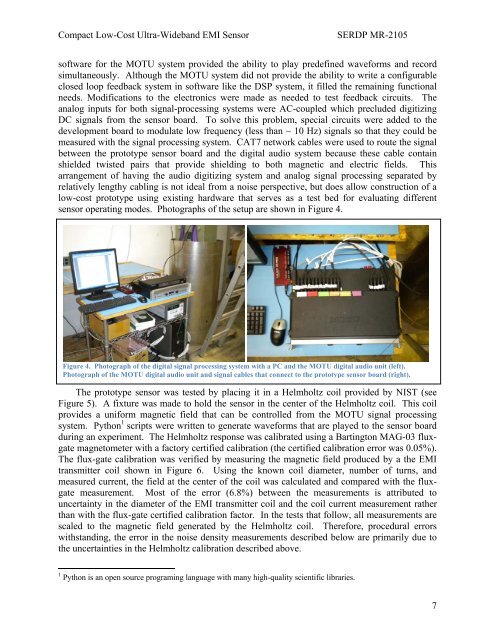
Compact Low-Cost Ultra-Wideb<strong>and</strong> EMI SensorSERDP MR-2105software for the MOTU system provided the ability to play predefined waveforms <strong>and</strong> recordsimultaneously. Although the MOTU system did not provide the ability to write a configurableclosed loop feedback system in software like the DSP system, it filled the remaining functionalneeds. Modifications to the electronics were made as needed to test feedback circuits. Theanalog inputs for both signal-processing systems were AC-coupled which precluded digitizingDC signals from the sensor board. To solve this problem, special circuits were added to thedevelopment board to modulate low frequency (less than ~ 10 Hz) signals so that they could bemeasured with the signal processing system. CAT7 network cables were used to route the signalbetween the prototype sensor board <strong>and</strong> the digital audio system because these cable containshielded twisted pairs that provide shielding to both magnetic <strong>and</strong> electric fields. Thisarrangement of having the audio digitizing system <strong>and</strong> analog signal processing separated byrelatively lengthy cabling is not ideal from a noise perspective, but does allow construction of alow-cost prototype using existing hardware that serves as a test bed for evaluating differentsensor operating modes. Photographs of the setup are shown in Figure 4.Figure 4. Photograph of the digital signal processing system with a PC <strong>and</strong> the MOTU digital audio unit (left).Photograph of the MOTU digital audio unit <strong>and</strong> signal cables that connect to the prototype sensor board (right).The prototype sensor was tested by placing it in a Helmholtz coil provided by NIST (seeFigure 5). A fixture was made to hold the sensor in the center of the Helmholtz coil. This coilprovides a uniform magnetic field that can be controlled from the MOTU signal processingsystem. Python 1 scripts were written to generate waveforms that are played to the sensor boardduring an experiment. The Helmholtz response was calibrated using a Bartington MAG-03 fluxgatemagnetometer with a factory certified calibration (the certified calibration error was 0.05%).The flux-gate calibration was verified by measuring the magnetic field produced by a the EMItransmitter coil shown in Figure 6. Using the known coil diameter, number of turns, <strong>and</strong>measured current, the field at the center of the coil was calculated <strong>and</strong> compared with the fluxgatemeasurement. Most of the error (6.8%) between the measurements is attributed touncertainty in the diameter of the EMI transmitter coil <strong>and</strong> the coil current measurement ratherthan with the flux-gate certified calibration factor. In the tests that follow, all measurements arescaled to the magnetic field generated by the Helmholtz coil. Therefore, procedural errorswithst<strong>and</strong>ing, the error in the noise density measurements described below are primarily due tothe uncertainties in the Helmholtz calibration described above.1 Python is an open source programing language with many high-quality scientific libraries.7


