

Final Report - Strategic Environmental Research and Development ...
Final Report - Strategic Environmental Research and Development ...
Final Report - Strategic Environmental Research and Development ...

Create successful ePaper yourself
Turn your PDF publications into a flip-book with our unique Google optimized e-Paper software.
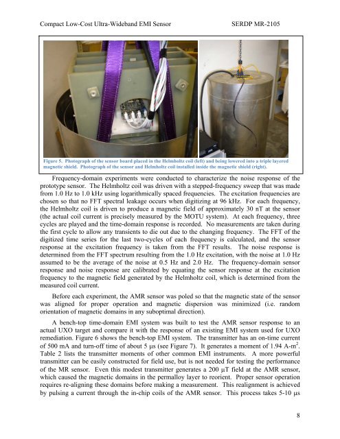
Compact Low-Cost Ultra-Wideb<strong>and</strong> EMI SensorSERDP MR-2105Figure 5. Photograph of the sensor board placed in the Helmholtz coil (left) <strong>and</strong> being lowered into a triple layeredmagnetic shield. Photograph of the sensor <strong>and</strong> Helmholtz coil installed inside the magnetic shield (right).Frequency-domain experiments were conducted to characterize the noise response of theprototype sensor. The Helmholtz coil was driven with a stepped-frequency sweep that was madefrom 1.0 Hz to 1.0 kHz using logarithmically spaced frequencies. The excitation frequencies arechosen so that no FFT spectral leakage occurs when digitizing at 96 kHz. For each frequency,the Helmholtz coil is driven to produce a magnetic field of approximately 30 nT at the sensor(the actual coil current is precisely measured by the MOTU system). At each frequency, threecycles are played <strong>and</strong> the time-domain response is recorded. No measurements are taken duringthe first cycle to allow any transients to die out due to the changing frequency. The FFT of thedigitized time series for the last two-cycles of each frequency is calculated, <strong>and</strong> the sensorresponse at the excitation frequency is taken from the FFT results. The noise response isdetermined from the FFT spectrum resulting from the 1.0 Hz excitation, with the noise at 1.0 Hzassumed to be the average of the noise at 0.5 Hz <strong>and</strong> 2.0 Hz. The frequency-domain sensorresponse <strong>and</strong> noise response are calibrated by equating the sensor response at the excitationfrequency to the magnetic field generated by the Helmholtz coil, which is determined from themeasured coil current.Before each experiment, the AMR sensor was poled so that the magnetic state of the sensorwas aligned for proper operation <strong>and</strong> magnetic dispersion was minimized (i.e. r<strong>and</strong>omorientation of magnetic domains in any suboptimal direction).A bench-top time-domain EMI system was built to test the AMR sensor response to anactual UXO target <strong>and</strong> compare it with the response of an existing EMI system used for UXOremediation. Figure 6 shows the bench-top EMI system. The transmitter has an on-time currentof 500 mA <strong>and</strong> turn-off time of about 5 s (see Figure 7). It generates a moment of 1.94 A-m 2 .Table 2 lists the transmitter moments of other common EMI instruments. A more powerfultransmitter can be easily constructed for field use, but is not needed for testing the performanceof the MR sensor. Even this modest transmitter generates a 200 T field at the AMR sensor,which caused the magnetic domains in the permalloy layer to reorient. Proper sensor operationrequires re-aligning these domains before making a measurement. This realignment is achievedby pulsing a current through the in-chip coils of the AMR sensor. This process takes 5-10 s8


