

Final Report - Strategic Environmental Research and Development ...
Final Report - Strategic Environmental Research and Development ...
Final Report - Strategic Environmental Research and Development ...

You also want an ePaper? Increase the reach of your titles
YUMPU automatically turns print PDFs into web optimized ePapers that Google loves.
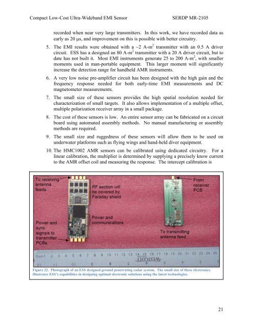
Compact Low-Cost Ultra-Wideb<strong>and</strong> EMI SensorSERDP MR-2105recorded when near very large transmitters. In this work, we have recorded data asearly as 20 s, <strong>and</strong> improvement on this is possible with better circuitry.5. The EMI results were obtained with a ~2 A-m 2 transmitter with an 0.5 A drivercircuit. ESS has a designed an 80 A-m 2 transmitter with a 20 A driver circuit, but todate has not built it. Most EMI instruments generate 25 to 200 A-m 2 , with smallermoments used in man-portable equipment. This larger moment will significantlyincrease the detection range for h<strong>and</strong>held AMR instruments.6. A very low noise pre-amplifier circuit has been designed with the high gain <strong>and</strong> thefrequency response needed for both early-time EMI measurements <strong>and</strong> DCmagnetometer measurements.7. The small size of these sensors provides the high spatial resolution needed forcharacterization of small targets. It also allows implementation of a multiple offset,multiple polarization receiver array in a small package.8. The cost of these sensors is low. An entire sensor array can be fabricated on a circuitboard using automated assembly methods. No manual manufacturing or assemblymethods are required.9. The small size <strong>and</strong> ruggedness of these sensors will allow them to be used onunderwater platforms such as flying wings <strong>and</strong> h<strong>and</strong>-held diver equipment.10. The HMC1002 AMR sensors can be calibrated using dedicated circuitry. For alinear calibration, the multiplier is determined by supplying a precisely know currentto the AMR offset coil <strong>and</strong> measuring the response. The intercept calibration isFigure 22. Photograph of an ESS designed ground penetrating radar system. The small size of these electronicsillustrates ESS’s capabilities in designing optimal electronic solutions using the latest technologies.21


