

Final Report - Strategic Environmental Research and Development ...
Final Report - Strategic Environmental Research and Development ...
Final Report - Strategic Environmental Research and Development ...

You also want an ePaper? Increase the reach of your titles
YUMPU automatically turns print PDFs into web optimized ePapers that Google loves.
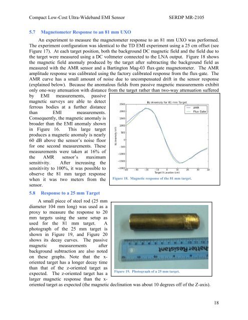
Compact Low-Cost Ultra-Wideb<strong>and</strong> EMI SensorSERDP MR-21055.7 Magnetometer Response to an 81 mm UXOAn experiment to measure the magnetometer response to an 81 mm UXO was performed.The experiment configuration was identical to the TD EMI experiment using a 25 cm offset (seeFigure 17). At each target position, both the background DC magnetic field <strong>and</strong> the field due tothe target were measured using a DC voltmeter connected to the LNA output. Figure 18 showsthe magnetic field anomaly produced by the target after subtracting the background field asmeasured with the AMR sensor <strong>and</strong> a Bartington Mag-03 flux-gate magnetometer. The AMRamplitude response was calibrated using the factory calibrated response from the flux-gate. TheAMR curve has a small amount of noise due to uncompensated drift in the sensor response(explained below). Because the anomalous fields from passive magnetic measurements exhibitonly one-way attenuation with distance from the target rather than two-way attenuation sufferedby EMI measurements, passivemagnetic surveys are able to detectferrous bodies at a further distancethan EMI measurements.Consequently, the magnetic anomaly isbroader than the EMI anomaly shownin Figure 16. This large targetproduces a magnetic anomaly is nearly60 dB above the sensor’s noise floorfor one second measurements. Thesemeasurements were taken at 16% ofthe AMR sensor’s maximumsensitivity. After increasing thesensitivity to 100%, it was possible toobserve the 81 mm target responsewhen it was two meters from the Figure 18. Magnetic response of the 81 mm target.sensor.5.8 Response to a 25 mm TargetA small piece of steel rod (25 mmdiameter 104 mm long) was used as aproxy to measure the response to 20mm targets using the same setup asused for the 81 mm target. Aphotograph of the 25 mm target isshown in Figure 19, <strong>and</strong> Figure 20shows its decay curves. The passivemagnetic measurements afterbackground subtraction are also notedon these graphs. Note that the x-oriented target has a longer decay timethan that of the z-oriented target asFigure 19. Photograph of a 25 mm target.expected. The z-oriented target has alarger magnetic response than the x-oriented target as expected (the magnetic declination was about 10 degrees off of the Z-axis).18


