TRC101 300-1000 MHz Transceiver - RF Monolithics, Inc.
TRC101 300-1000 MHz Transceiver - RF Monolithics, Inc.
TRC101 300-1000 MHz Transceiver - RF Monolithics, Inc.

You also want an ePaper? Increase the reach of your titles
YUMPU automatically turns print PDFs into web optimized ePapers that Google loves.
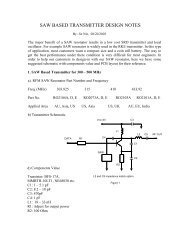
916 <strong>MHz</strong> 2.2e-3 – j1.55e-2 9 + j63 11.2nHThese values are what the <strong>RF</strong> port pins want to “see” as an antenna load for maximum power transfer.Antennas ideally suited for this would be a Dipole, Folded Dipole, and Loop. For all transmit antennaapplications a bias or “choke” inductor must be included since the <strong>RF</strong> outputs are open-collector type.The <strong>TRC101</strong> may also drive a single ended 50 Ohm load, such as a monopole antenna, using thematching circuit as shown in Figure 1. Use of a balun would provide an optimum power transfer, but thematching circuit of Figure 1 has been optimized for use with discrete components, reducing the costassociated with use of a balun. The matching component values for a 50 Ohm load for each band aregiven in Table 2.Table 2.Ref Des 315 433 868 916C1 6.8pF 5.1pF 2.7pF 2.7pFC2 3.9pF 2.7pF 1.2pF 1.2pFC4 .1uF .1uF .1uF .1uFC7 100pF 100pF 100pF 100pFL1 56nH 33nH 8.2nH 8.2nHL2 390nH 390nH 100nH 100nHL3 68nH 47nH 22nH 22nHAntenna Design ConsiderationsThe <strong>TRC101</strong> is designed to drive a differential output such as a Dipole antenna or a Loop. The loopantenna is ideally suited for applications where compact size is required. The dipole is typically not anattractive option for compact designs due to its inherent size at resonance and distance needed awayfrom a ground plane to be an efficient antenna. A monopole antenna can be used with the addition of abalun or by using the matching circuit in Figure 1.PCB Layout ConsiderationsOptimal PCB layout is very critical. For optimal transmit and receive performance, the trace lengths at the<strong>RF</strong> pins must be kept as short as possible. Using small, surface mount components, like 0402 or 0603,will yield the best performance as well as keep the <strong>RF</strong> port compact. Make all <strong>RF</strong> connections short anddirect. A good rule of thumb to adhere to is add 1nH of series inductance for every 0.1” of trace length.The crystal oscillator is also affected by additional trace length as it adds parasitic capacitance to theoverall load of the crystal. To minimize this effect place the crystal as close as possible to the chip andmake all connections short and direct. This will minimize the effects of “frequency pulling” that straycapacitance may introduce and allows the internal load capacitance of the chip to be more effective inproperly loading the crystal oscillator circuit.If using an external processor, the <strong>TRC101</strong> provides an on-chip clock for that purpose. Even though thisis an integrated function, long runs of the clock signal may radiate and cause interference. This candegrade receiver performance as well as add harmonics or unwanted modulation to the transmitter.Keep clock connections as short as possible and surround the clock trace with an adjacent ground planepour where needed. This will help in reducing any radiation or crosstalk due to long runs of the clocksignal.Good power supply bypassing is also essential. Large decoupling capacitors should be placed at thepoint where power is applied to the PCB. Smaller value decoupling capacitors should then be placed ateach power point of the chip as well as bias nodes for the <strong>RF</strong> port. Poor bypassing lends itself toconducted interference which can cause noise and spurious signals to couple into the <strong>RF</strong> sections,significantly reducing performance.www.<strong>RF</strong>M.com Email: info@rfm.com Page 5 of 42©by <strong>RF</strong> <strong>Monolithics</strong>, <strong>Inc</strong>. <strong>TRC101</strong> - 4/8/08