C21e tile installation guide - Solarcentury
C21e tile installation guide - Solarcentury
C21e tile installation guide - Solarcentury

Create successful ePaper yourself
Turn your PDF publications into a flip-book with our unique Google optimized e-Paper software.
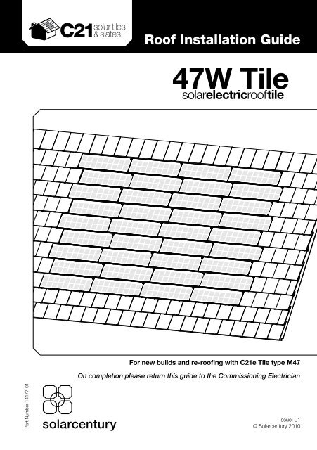
Roof Installation GuideContentsTitle.....................................................................Page1. Health and Safety........................... 11.1 General Guidance.................... 11.2 Electrical Hazards.................... 11.3 Preparation for <strong>C21e</strong>Installation............................... 22. Components................................... 32.1 Equipment Required................ 32.2 The Roof Accessories Box....... 33. Pre-Installation Checks.................. 54. Roof Preparation............................ 64.1 General Recommendations..... 64.2 Marking the Area for the<strong>C21e</strong> System.......................... 74.3 Positioning the Field Cables .... 87. Liability............................................ 218. Warranty.......................................... 22Appendices......................................... 25Appendix 1: <strong>C21e</strong> Tile Schematic- Typical Layout &Fixing Detail (GB)..................... 25Appendix 2: String Layouts............ 27Appendix 3: String CheckerUser Guide.............................. 28Appendix 4: Component Listand Roof Dimensions.............. 295. <strong>C21e</strong> Installation............................. 95.1 Laying the Bottom Section ofRoof Tiles................................ 95.2 Laying the Right Section ofRoof Tiles................................ 105.3 Fitting the First <strong>C21e</strong>Column................................... 115.4 Checking the <strong>C21e</strong> CableConnections........................... 155.5 Laying the Remaining <strong>C21e</strong>Columns................................. 165.6 Completing the Cabling........... 176. Completing the Tiling..................... 19Part Number 14177-01
<strong>tile</strong>1. Health and Safety1.1 General Guidance• Construction (Design and Management) Regulations 2007 (CDM)* andgeneral construction site training must be followed.• Safe working at heights training should be adhered to.• Anyone handling photovoltaic (PV) modules should be trained in correctmanual handling practice.• All appropriate Health and Safety regulations should be followed correctly.• Avoid installing the system in poor weather conditions, including strongwind, rain, ice or snow.• The <strong>tile</strong> courses should be layed according to British Standard 5534: 2003*‘Code of practice for slating and tiling (including shingles)’ unless toldotherwise.• Install all components as specified within this <strong>guide</strong> to ensure weathertightness.1.2 Electrical HazardsYou must be aware of the following:WARNING: PV modules produce a DC voltage whenever exposed to light.This voltage cannot be switched off.WARNING: Care must be taken not to cut or damage cable insulation orexpose bare wire.• PV modules are pre-wired with touch-proof connectors to prevent anelectrical shock during general handling.Part Number 14177-011• PV modules do not present a risk as long as appropriate safety practicesare followed at all times during <strong>installation</strong>.• All work must be carried out with the <strong>C21e</strong> system disconnected from themains electrical supply.*latest at time of print
Roof Installation Guide1. Health and Safety continued1.3 Preparation for <strong>C21e</strong> InstallationFollow the guidance below to ensure the <strong>C21e</strong> units are installed and handledcorrectly:• Use this <strong>installation</strong> <strong>guide</strong> alongside your system design <strong>guide</strong> and roofschematic (see Appendix 1) to determine the location and layout of the<strong>C21e</strong> system on the roof.• Use this <strong>installation</strong> <strong>guide</strong> alongside the string diagram (see Appendix 2) tounderstand how to connect the <strong>C21e</strong> cables together.• Ensure all cable connectors are dry and free of dirt before makingconnections.• Ensure no cable ends are left exposed to the weather during work breaksor after completion of works. Keep the <strong>C21e</strong> units in a weatherproofenvironment before <strong>installation</strong>.• Carry the <strong>C21e</strong> units with both hands by the frame, and avoid scratchingthe glass.• Only load as many <strong>C21e</strong> units onto the roof as you expect to install duringthe session.• Secure or remove any uninstalled units before leaving the roof to avoidpossible wind damage.• Do NOT walk on the glass surface of the <strong>C21e</strong> units. While robust, extremepoint pressure may cause the toughened glass laminate to shatter.• Do not leave tools or unsecured materials above the <strong>C21e</strong> <strong>installation</strong> area,to avoid potential damage to the units.2Part Number 14177-01
<strong>tile</strong>2. Components2.1 Equipment Required• Standard roofing tool kit• <strong>C21e</strong> Specific Tools:- Screwdriver with pozi-drive head.- String checker with specialist touch proof test leads, to check cable connections(available to order from <strong>Solarcentury</strong>).2.2 The Roof Accessories BoxWhen ordered as a complete system, the accessories box will contain thefollowing components required for the on roof <strong>installation</strong> of the <strong>C21e</strong> units.Components included in the standard accessories box:Return Cables(layout dependent, 1per column)<strong>C21e</strong> Self Tapping Screws(M4.5 X 45 Countersunk)Screws are included withineach carton of <strong>C21e</strong> units.Field Cables(2 per string)Part Number 14177-013The quantities of components vary by system size and layout (see Appendix 4 for details).
<strong>tile</strong>4. Roof Preparation continued4.2 Marking the Area for the <strong>C21e</strong> SystemTo make sure the <strong>C21e</strong> system is installed in the correct position on the roof,you must mark the area out before you begin (Diagram 2).• Refer to the Appendices and your Architect’s drawings to understand whichlayout to use and where the system will be located on the roof.Design RulesThe area that the <strong>C21e</strong> system will cover on the roof has been calculated usingthe following design rules (Diagram 2). These rules exist to ensure a weathertight<strong>installation</strong>.• Allow a minimum of one conventional <strong>tile</strong> between the edge <strong>C21e</strong> units andthe verge or equivalent obstruction.• Allow at least one course of conventional <strong>tile</strong>s below the <strong>C21e</strong> area, and atleast one course of conventional <strong>tile</strong>s above the <strong>C21e</strong> area.• Lay <strong>C21e</strong> <strong>tile</strong>s broken bond to match the fixing specification of theconventional <strong>tile</strong>s.• The system is central to the roof and not close to any vents.See Appendix 4 for more detail of required space for each <strong>C21e</strong> system size.Consult the Site Manager or System Designer if the drawings do notconform to the above design rules.The example <strong>C21e</strong> system in this <strong>guide</strong> uses 4 columns of 9 rows.Part Number 14177-017
Roof Installation Guide4. Roof Preparation continued• When the layout and location of the <strong>C21e</strong> system has been identified, markthis area on the roof.Minimum startdistance fromridge/eaves= 1 concrete<strong>tile</strong> courseAt least 1 concrete <strong>tile</strong>width from each vergeDiagram 24.3 Positioning the Field CablesBefore fixing the <strong>C21e</strong> units you must consider how the cables are connectedand where they enter the roof space.• Refer to the string diagram for an overview of cable positions andconnections (Appendix 2).• Identify where the Field Cables will need to enter the roof (at a suitable lap inthe membrane).8Part Number 14177-01
5. <strong>C21e</strong> Installation<strong>tile</strong>5.1 Laying the Bottom Section of Roof Tiles• Lay the bottom courses of conventional roof <strong>tile</strong>s using standard practicefrom the eaves up to the area marked for the <strong>C21e</strong> system.TIP: Before fixing the course of roof <strong>tile</strong>s below the marked area,check the spacing. Each <strong>C21e</strong> replaces four roof <strong>tile</strong>s; they shouldbe laid broken bond to match the roof <strong>tile</strong>s (see Diagram 3 below). Insome situations you may need to adjust the shunt of the roof <strong>tile</strong>s.Diagram 3Part Number 14177-019
Roof Installation Guide5. <strong>C21e</strong> Installation continued5.2 Laying the Right Section of Roof Tiles• Install roof <strong>tile</strong>s to the right side of the <strong>C21e</strong> area as you would at a verge(i.e. using a whole <strong>tile</strong> or a <strong>tile</strong> and a half). This will ensure weather tightnessand match the grain of the <strong>tile</strong>s below.Diagram 4WARNING: Make sure there is at least one roof <strong>tile</strong> between the edge ofthe <strong>C21e</strong> area and the verge of the roof (or equivalent obstruction).10Part Number 14177-01
<strong>tile</strong>5. <strong>C21e</strong> Installation continued5.3 Fitting the First <strong>C21e</strong> ColumnIt is advised that the <strong>C21e</strong> units are laid column by column. This allows the<strong>C21e</strong> cables to be connected and tested as you go.The first column of <strong>C21e</strong> units should begin on the lowest batten in the markedarea and sit flush with the concrete <strong>tile</strong>s on the right.• Lay the first <strong>C21e</strong> face down as shown in Diagram 5 and pass both <strong>C21e</strong>cables under the batten.• Firmly connect the black <strong>C21e</strong> cable to the end of the Return Cable(Diagram 5a).• Pass the Return Cable from the <strong>C21e</strong> <strong>tile</strong>, under the battens, to the top ofthe column.TIP: The longer Field Cables (that enter the roof space) look similar tothe Return Cables. To help distinguish between them, the Return Cableshave a red tag and the Field Cables are marked with one of the followingsymbols:Part Number 14177-0111WARNING: Make sure there is no gap between any connectors as this willcause the system to fail.TIP: To ensure a firm connection, push the connectors together until they click.
Roof Installation Guide5. <strong>C21e</strong> Installation continuedReturn cableDiagram 5aDiagram 5WARNING: Ensure that there are no upstanding nails that could damagethe glass surface of the <strong>C21e</strong>.WARNING: Make sure that when you lay the Return Cables and<strong>C21e</strong> cables up the roof they lie close to each other. This is importantthroughout the <strong>installation</strong> to prevent electrical interference.12Part Number 14177-01
<strong>tile</strong>5. <strong>C21e</strong> Installation continued• Turn the <strong>C21e</strong> unit the correct way round with the nib resting on the batten,as with a normal <strong>tile</strong>. The frame should interlock with the <strong>tile</strong> to its right(Diagram 6a).• Use an electric screw driver and the screws provided to fix the <strong>C21e</strong> unit tothe batten through the holes on the <strong>C21e</strong> frame (Diagram 6).Diagram 6aDiagram 6WARNING: Only use the screws and washers supplied. These form part ofthe system designed to provide a weather tight seal and are correctly sizedfor the <strong>C21e</strong> units. Use the correct number of screws every time. Using anyother screws will invalidate the warranty.WARNING: Do NOT use a hammer to fix the <strong>C21e</strong>.Part Number 14177-0113WARNING: Ensure that there is no risk of the cables being trapped orpierced when the <strong>C21e</strong> unit is fixed.TIP: Work from right to left when tightening the screws to ensure the <strong>C21e</strong> <strong>tile</strong>fits correctly.
Roof Installation Guide5. <strong>C21e</strong> Installation continued• Install the right set of roof <strong>tile</strong>s on the batten above, ready for the next <strong>C21e</strong>unit, as explained in 5.2.• Lay the next <strong>C21e</strong> face down on the batten. Firmly connect its black cableto the red cable from the <strong>C21e</strong> on the course below.Diagram 7• Pass the red cable from this <strong>C21e</strong> under the batten above ready to connectto the next <strong>C21e</strong> in the column.WARNING: Ensure that the <strong>C21e</strong> cables lay close to the Return Cableand that the cables are not trapped between the <strong>tile</strong> and batten whenfixing the <strong>C21e</strong> units.• Turn the <strong>C21e</strong> unit the correct way round with the nib resting on the batten,as with a normal <strong>tile</strong>.• Fix the <strong>C21e</strong> to the batten using the screws provided.WARNING: The lower edge of the <strong>C21e</strong> frame should sit on the frameof the <strong>C21e</strong> below, but should never extend more than 20 mm onto theglass surface, or the cells will be shaded voiding the warranty.• Lay the remaining <strong>C21e</strong> units in the column following the same method.14Part Number 14177-01
<strong>tile</strong>5. <strong>C21e</strong> Installation continued5.4 Checking the <strong>C21e</strong> Cable Connections• At the top of each column, ensure that the <strong>C21e</strong> cables are left in anaccessible position. They will be connected later in the <strong>installation</strong>.<strong>Solarcentury</strong> recommends that a string check is carried out for each column tocheck the cable connections (Diagram 8).• To carry out a string check follow the instructions in Appendix 3.Part Number 14177-0115WARNING: Always use safety leads with the string checker.Never use standard meter probes to avoid risk of electrocution.Diagram 8
<strong>tile</strong>5. <strong>C21e</strong> Installation continued5.6 Completing the CablingWhen all the <strong>C21e</strong> units are fixed in place, the cables at the top of eachcolumn must be connected together to complete the String or Strings.The following example explains how to connect a two String, 36 <strong>C21e</strong> unitsystem. For single String systems please refer to Appendix 2. Consult Appendix4 to confirm the number of Strings for the system size you are installing.For all two String systems you should consider the <strong>C21e</strong> units as two separatearrays, with an equal number of <strong>C21e</strong> units in each array.For example, a system of 36 <strong>C21e</strong> units should be split evenly into two Strings,each with 18 <strong>C21e</strong> units. See Diagram 10 for details.Roofing membranePart Number 14177-0117Diagram 10WARNING: Each String in an array should always have the same number of <strong>C21e</strong>units. Uneven Strings will cause the system to fail and invalidate the warranty.
Roof Installation GuideRed <strong>C21e</strong>cable5. <strong>C21e</strong> Installation continuedFor the first String:• Start at the top of the first (right) <strong>C21e</strong> column and connect the ReturnCable to a Field Cable (marked with one of the symbols ).• At the top of each other column in this String, connect the Return Cable tothe spare red <strong>C21e</strong> cable from the previous column.• At the final <strong>C21e</strong> column connect the remaining red <strong>C21e</strong> cable to a FieldCable (see Diagram 10).• Bring the Field Cables together above this column and carry out a Stringcheck for the completed String by following the instructions provided inAppendix 2. Record the results on the reverse of this <strong>guide</strong>.• Use a cable tie (or equivalent) to fasten the cables to the battens. Securingthe cables will avoid potential stress if they are pulled from within the loftspace during the electrical <strong>installation</strong>.• Take the ends of the Field Cables and push them through a lap in themembrane at the top of the last column in the String and into the loft space.302928272624Red <strong>C21e</strong>cable242322212019Red <strong>C21e</strong>cableRed <strong>C21e</strong>cableRed <strong>C21e</strong>cableFor the second String:• Repeat the steps above starting at the top of the next column.• You should be left with two identical arrays, with an equal number of <strong>C21e</strong>units in each string, as shown in Diagram 11 below.Red <strong>C21e</strong>cableRed <strong>C21e</strong>cable181716151413Red<strong>C21e</strong> cable181716151413Red <strong>C21e</strong> cable2nd String1st StringDiagram 11WARNING: Ensure that the Field Cables and Return Cables at the topof the <strong>installation</strong> lie close to each other.Red <strong>C21e</strong>Red <strong>C21e</strong>cablecable18Part Number 14177-01
<strong>tile</strong>6. Completing the TilingWhen all the <strong>C21e</strong> units have been fitted, a string check for the system is complete,and the Field Cables passed into the loft space, the remaining concrete <strong>tile</strong>s can belaid.• Install the concrete <strong>tile</strong>s on the left side of the <strong>C21e</strong> units as you would ata verge (i.e. using a whole <strong>tile</strong> or a <strong>tile</strong> and a half). This will ensure weathertightness and match the grain of the <strong>tile</strong>s below.• Lay a course of conventional <strong>tile</strong>s on the batten above the <strong>C21e</strong> units.Diagram 12Part Number 14177-0119WARNING: The headlap should never exceed 120mm. A headlap greaterthan this will cover the PV cells and cause the system to fail, invalidating thewarranty.
Roof Installation Guide6. Completing the Tiling continued• Continue laying the <strong>tile</strong>s for the remainder of the roof using standard practice.Diagram 13WARNING: Take care not to drop tools or materials on the <strong>C21e</strong> units.NOTE: Please remember to dispose of all unused materials safely, andrecycle where possible.20Part Number 14177-01
<strong>tile</strong>7. Disclaimer of LiabilityInstructions given in this <strong>guide</strong> are general <strong>guide</strong>lines only for the design,<strong>installation</strong> and use of the <strong>C21e</strong> units together with any associated components.Due to the wide variety of materials, equipment and sites which an <strong>installation</strong> mayinvolve this <strong>guide</strong> cannot consider the individual technical requirements relevant toevery individual project and/or site.If you have detailed questions about any specific project and/or site please contact<strong>Solarcentury</strong>.Before installing the <strong>C21e</strong> units, contact the appropriate authorities to determinethe permissions, consents, approvals, licenses, <strong>installation</strong> and inspectionrequirements which apply to the site and the <strong>installation</strong>. <strong>Solarcentury</strong> accepts noresponsibility or liability in this respect.This <strong>guide</strong> is based on <strong>Solarcentury</strong>’s knowledge and experience and is believed tobe reliable but the <strong>guide</strong> does not constitute a warranty, express of implied.<strong>Solarcentury</strong> does not assume responsibility and expressly disclaims liability forany loss, damage or expense arising out of or in any way connected with incorrecthandling, <strong>installation</strong>, operation, use or maintenance of the <strong>C21e</strong> units.No responsibility is assumed by <strong>Solarcentury</strong> for any infringement of patents orother rights of third parties that may result from use of the <strong>C21e</strong> units. No license isgranted by implication or otherwise under any patent or patent rights.<strong>Solarcentury</strong> reserves the right to make changes to the Product, the specificationsor this <strong>guide</strong>, without prior notice.Incorrect and/or faulty <strong>installation</strong>, operation, use or maintenance may bedangerous and may invalidate any warranty which may apply to the <strong>C21e</strong> units.End users should remember that the <strong>C21e</strong> units require professional <strong>installation</strong>using special tools and expert know-how.No part of this <strong>guide</strong> may be reproduced in any form by any means without<strong>Solarcentury</strong>’s express written consent.Part Number 14177-0121
Roof Installation Guide8. WarrantyProduct Warranty for <strong>C21e</strong> solar electric roof <strong>tile</strong>s in United Kingdom and IrelandModel number: <strong>C21e</strong> Tile M47-H38This warranty applies to the <strong>Solarcentury</strong> Modules with the model numbers listedabove which were purchased from <strong>Solarcentury</strong> or an authorised distributor, installeror reseller (an “Authorised Distributor”) and purchased and installed in the territoryindicated above.In this warranty “Product” means each of the listed Modules individually.In addition to your statutory rights, which are unaffected, <strong>Solarcentury</strong> guarantees that,from the date of original purchase from <strong>Solarcentury</strong> or its Authorised Distributor (or, inthe absence of proof of purchase, from the date of manufacture):A Materials and Workmanship – 10 yearsThe Product shall be free from defects in materials and workmanship inmanufacture for a period of 10 years.B Power Output – 25 years(1) The power rating of the Product will remain at 90% or more of its Peak Powerrating 1 for 10 years; and(2) The power rating of the Product will remain at 80% or more of its Peak Powerrating for 25 years.If a Product fails to meet the standard guaranteed and the conditions below aremet, then <strong>Solarcentury</strong> will, in its sole discretion: (a) repair or replace the defectiveProduct with an equivalent product; or (b) refund the purchase price of theProduct; or (c) provide the owner with additional PV modules required to makeup the power lost or provide to the owner compensation for power lost up to amaximum value of the purchase price of the Product, such loss in power havingbeen proved to have been suffered by the owner of the Product and determinedby <strong>Solarcentury</strong> (in its sole and absolute discretion) to be due to defects inmaterials or workmanship.Notwithstanding the above, if the Product is used in any non-land basedapplications, any Power Output warranty claims must be made within 10 years.1In this context, the power rating of the Product will be that measured by or on behalf of <strong>Solarcentury</strong> underStandard Test Conditions (irradiance of 1000W/m2, light spectrum AM 1.5g and a cell temperature of 25degrees Celsius) and may not equate to that produced by the Product under other conditions. The relevant“Peak Power” is defined in <strong>Solarcentury</strong>’s Datasheet at the time of shipment.22Part Number 14177-01
<strong>tile</strong>8. Warranty continued<strong>Solarcentury</strong> shall have no liability for any other costs or losses howsoever arising(and for the avoidance of doubt) this guarantee does not include the costs of labouror transport or any other associated costs including, without limitation, costs involvedin removing or returning the Product to <strong>Solarcentury</strong>, or its re-<strong>installation</strong>. Any Product(or parts) replaced shall become the property of <strong>Solarcentury</strong> and the replacementProduct shall only have the warranty cover for the remainder of the original warrantyperiod.The conditions:Part Number 14177-01(a)(b)(c)(d)(e)(f)(g)(h)(i)(j)(k)23The Product is properly installed in a suitable location in accordance with<strong>Solarcentury</strong>’s Datasheets and instructions for design, <strong>installation</strong>, operationand maintenance of the Product (together the “Product Guide”) and inaccordance with all applicable laws and standards as updated and applicableat the date of <strong>installation</strong> whether or not those standards are identified in theProduct Guide;The Product has not been removed from the location in which it was firstinstalled, nor connected to, or used with, any unapproved device;The Product has not, in <strong>Solarcentury</strong>’s absolute judgment, been damagedduring transportation, delivery, storage, handling or <strong>installation</strong>;The Product has not, in <strong>Solarcentury</strong>’s absolute judgment, suffered damagecaused by extraneous causes such as structural movement of the roof,accident, an impact of significant force, fire, lightning, flood, severe weather,interference by animals, insect and pest infestation or other Acts of God orother events, howsoever caused, reasonably beyond <strong>Solarcentury</strong>’s control;The Product has not been subject to misuse, neglect, abuse, alteration orimproper application;The Product has not been exposed to conditions (including, where applicable,excessive levels of pollution or wind speeds) at the property where it wasinstalled which are more adverse than those which the Product is designed towithstand as stated in the Product Guide;The Product has been operated and maintained in accordance with theProduct Guide;The labels, serial numbers or barcodes on the Product or any of itscomponents have not been altered, removed or made illegible;Any alleged defect in materials is not merely cosmetic or due to normal andreasonable wear and tear of the Product;<strong>Solarcentury</strong> has been paid in full for the Product;A claim is notified: (i) in accordance with the procedure set out below, and asset out in the Product Guide; (ii) within the applicable warranty period set outabove; and (iii) within two months of the first date on which problems with theProduct were detected or ought to have been detected.
Roof Installation Guide8. Warranty continuedIf any of the above conditions are not met then <strong>Solarcentury</strong> shall have no obligationsunder this guarantee and no rights shall accrue as a result of this warranty.Procedure for making a claim:Before making a claim, you should review the Product Guide to make sure that youhave followed all the guidance.If after reviewing the Product Guide you are still concerned that the Product is notperforming as it should, please contact your installer or maintainer in the first instance.If your installer or maintainer considers the Product is not performing according to thewarranty, please (together with the assistance of your installer or maintainer) provide<strong>Solarcentury</strong> with the details below so that we can consider your claim, marking yourcorrespondence for the attention of the <strong>Solarcentury</strong> Customer Services. Pleaseinclude:• Confirmation that you have reviewed the Product Guide but the resultsindicate that the Product may be failing to perform to the guaranteedstandard;• Confirmation that conditions (a) to (k) above are met;• A detailed description of the Product failure, including supporting images;• Adequate documentation of proof of purchase (including details of purchasereceipts);• The Product’s serial number; and• Details of when and by whom the Product was purchased and installed andthe address of the property at which it was installed.Solar Century Holdings Limited91-94 Lower MarshLondon SE1 7AB020-7803-0180customerservices@<strong>Solarcentury</strong>.com24Part Number 14177-01
<strong>tile</strong>Appendix 1: <strong>C21e</strong> Tile Schematic - Typical Layout & Fixing Detail (GB)Timber Rafter300-345 Batten CentresPart Number 14177-0125Timber Batten (25x50 recommended)<strong>Solarcentury</strong> <strong>C21e</strong>Solar Electric Roof TileNOTES:Page 1 of 2This drawing is to show the use of<strong>Solarcentury</strong> Holdings Ltd products.For details of wall or roof constructionssee Architects drawings.REV:SHEET:SCALE:04 A3 NTSEach <strong>C21e</strong> <strong>tile</strong> fixed using 4 No. Ø4.5x45 SSself tapping screws with EPDM washersRoofing MembraneConcrete TileSIDE VIEWDRAWING NAME:DRAWING NO:11380-01 C21E TILE FORMAT - TYPICAL LAYOUT & FIXING DETAIL (GB)
Roof Installation GuideAt least one course of concrete <strong>tile</strong>sabove <strong>C21e</strong> <strong>tile</strong>sAt least one wholeconcrete <strong>tile</strong> between<strong>C21e</strong> <strong>tile</strong>s and theroof vergeNOTES:Page 2 of 2PLAN VIEWDRAWING NO:DRAWING NAME:11380-01 C21E TILE FORMAT - TYPICAL LAYOUT & FIXING DETAIL (GB)This drawing is to show the use of<strong>Solarcentury</strong> Holdings Ltd products.For details of wall or roof constructionssee Architects drawings.REV:SHEET:SCALE:04 A3 NTS26Part Number 14177-01
<strong>tile</strong>Appendix 2: String LayoutsFor all standard layouts, individual columns are connected in exactly the same wayusing the Return Cables. The length of the Return Cable will correspond to the layoutselected at the time of ordering.Final connection of the columns to form the String or Strings should follow theguidance in Appendix 4.Single String Systems (12 to 30 units)For these system sizes, all of the <strong>C21e</strong> units are connected together to form asingle String, as shown in the example below:Red <strong>C21e</strong>cableRed <strong>C21e</strong>cableRed <strong>C21e</strong>cableRed <strong>C21e</strong>cableRed <strong>C21e</strong>cable30242923282227212620241930 <strong>C21e</strong> unit examplePart Number 14177-01Red <strong>C21e</strong>cable27Two String Systems (36 to 84 <strong>C21e</strong> units)For these system sizes, 2 strings are needed irrespective of the physical rooflayout, as shown in the worked example in this <strong>guide</strong>, Section 5.6.Red <strong>C21e</strong>cableRed<strong>C21e</strong> cable1818WARNING: The number of strings is dependent on the System Design17for the size of the <strong>C21e</strong> array. This should not be changed. (See Appendix174 for more details.)1615141316151413Red <strong>C21e</strong> cable
Appendix 3: String Checker User GuideFor <strong>C21e</strong> type M45Roof Installation Guide1. Connect the red test lead to the V’Ω inputconnector (1) and the black test lead to theCOM input connector (2).2. From the off position, turn the centre dialone place in an anti-clockwise direction.The Function Range is now set to 600Vdc (3).3. Connect the opposite ends of the test leadsto the output strings of the <strong>C21e</strong> units.Note the connectors will only connect one way.4. The display will now read the DC voltageproduced by the <strong>C21e</strong> Units.5.The voltage will vary according to theamount of daylight falling on the <strong>C21e</strong> Units.Please refer to the table on the back page as anapproximate <strong>guide</strong> to the measurement.3.600Vdc6. If the value displayed on the String Checkerscreen is below the figure for an overcast daythen there is an error with the <strong>installation</strong> andstring connection.7. In this situation, retrace the string connectionthrough from the start ensuring the connectorsare pushed firmly together with no gaps and thatthe <strong>C21e</strong> Units follow the Stringing Diagram forthe given layout.8. Once the reading is correct, switch the StringChecker to the OFF position.9. You can now disconnect the test leads andcontinue with the <strong>C21e</strong> <strong>installation</strong> following the<strong>C21e</strong> On Roof Installation Guide.2.COM inputconnector1.V ’Ω inputconnectorPlease refer to the user manual for full operating instructions.String checkers with touch proof test leads are available to order from <strong>Solarcentury</strong>.28Part Number 14177-01
<strong>tile</strong>Appendix 4: Component List and Roof DimensionsPart Number 14177-01System SizeReturn Cables x Pairs of FieldkWp Strings Rows Columns(<strong>C21e</strong> Units)Length (m) CablesScrews12 1 1 x 4.5m6 2 2 x 3m12 0.56 14 3 3 x 2m3 4 4 x 2m1 482 6 6 x 2m1 12 n/a18 1 1 x 6m9 2 2 x 4.5m18 0.85 16 3 3 x 3m3 6 6 x 2m1 722 9 9 x 2m1 18 n/a12 2 2 x 4.5m8 3 3 x 3m24 1.13 16 4 4 x 3m4 6 6 x 2m1 963 8 8 x 2m2 12 12 x 2m15 2 2 x 6m10 3 3 x 4.5m30 1.41 16 5 5 x 3m5 6 6 x 2m1 1203 10 10 x 2m2 15 15 x 2m18 2 2 x 6m9 4 4 x 4.5m36 1.69 2 6 6 6 x 3m2 1443 12 12 x 2m2 18 18 x 2m42 1.97 27 6 6 x 3m3 14 14 x 2m2 16812 4 4 x 4.5m8 6 6 x 3m48 2.26 2 6 8 8 x 3m2 1924 12 12 x 2m3 16 16 x 2m54 2.54 29 6 6 x 4.5m3 18 18 x 2m2 21615 4 4 x 6m10 6 6 x 4.5m60 2.82 2 6 10 10 x 3m2 2405 12 12 x 2m3 20 20 x 2m66 3.10 2 11 6 6 x 4.5m 2 26418 4 4 x 6m12 6 6 x 4.5m72 3.38 2 9 8 8 x 4.5m 2 2886 12 12 x 3m4 18 18 x 2m78 3.67 2 13 6 6 x 4.5m 2 31214 6 6 x 6m84 3.95 2 7 12 12 x 3m2 3366 14 14 x 3m29<strong>C21e</strong> Layout Option(1)Roof Components Provided (2)Notes: (1) Additional layouts may be possible for some system sizes, but will require additional Return Cables to those provided in the Standard Systems.(2) The components provided in each system will support the layouts as shown, a small quantity of spare screws are provided.(3) One Return Cable is provided per <strong>C21e</strong> column. The Cable length is dependent on the number of <strong>C21e</strong> rows in the layout.(4) The dimensions stated are for guidance and are based on the <strong>C21e</strong> Design Rules for the compatible <strong>tile</strong>s listed on the datasheet.Please refer to the <strong>C21e</strong> Tile datasheet for full specification details.System Size(<strong>C21e</strong> Units)12182430364248546066727884
Roof Installation Guide<strong>C21e</strong> Layout Option(1)Dimensions of C21 Array(laid broken bond, butexcluding <strong>tile</strong> border)Total recommended roof dimensionsrequired including the <strong>tile</strong> border (4), forcompatible <strong>tile</strong>s with a 90mm headlapSystem Size(<strong>C21e</strong> Units)Rows Columns Length (m) Width (m) Length (m) Width (m) Area (m 2 )12 1 3.96 1.33 4.62 1.93 8.926 2 1.98 2.51 2.64 3.11 8.21124 3 1.32 3.69 1.98 4.29 8.493 4 0.99 4.87 1.65 5.47 9.032 6 0.66 7.23 1.32 7.83 10.341 12 0.33 14.31 0.99 14.91 14.7618 1 5.94 1.33 6.60 1.93 12.749 2 2.97 2.51 3.63 3.11 11.29186 3 1.98 3.69 2.64 4.29 11.333 6 0.99 7.23 1.65 7.83 12.922 9 0.66 10.77 1.32 11.37 15.011 18 0.33 21.39 0.99 21.99 21.7712 2 3.96 2.51 4.62 3.11 14.378 3 2.64 3.69 3.30 4.29 14.16246 4 1.98 4.87 2.64 5.47 14.444 6 1.32 7.23 1.98 7.83 15.503 8 0.99 9.59 1.65 10.19 16.812 12 0.66 14.31 1.32 14.91 19.6815 2 4.95 2.51 5.61 3.11 17.4510 3 3.3 3.69 3.96 4.29 16.99306 5 1.98 6.05 2.64 6.65 17.565 6 1.65 7.23 2.31 7.83 18.093 10 0.99 11.95 1.65 12.55 20.712 15 0.66 17.85 1.32 18.45 24.3518 2 5.94 2.51 6.60 3.11 20.539 4 2.97 4.87 3.63 5.47 19.8636 6 6 1.98 7.23 2.64 7.83 20.673 12 0.99 14.31 1.65 14.91 24.602 18 0.66 21.39 1.32 21.99 29.03427 6 2.31 7.23 2.97 7.83 23.263 14 0.99 16.67 1.65 17.27 28.5012 4 3.96 4.87 4.62 5.47 25.278 6 2.64 7.23 3.30 7.83 25.8448 6 8 1.98 9.59 2.64 10.19 26.904 12 1.32 14.31 1.98 14.91 29.523 16 0.99 19.03 1.65 19.63 32.39549 6 2.97 7.23 3.63 7.83 28.423 18 0.99 21.39 1.65 21.99 36.2815 4 4.95 4.87 5.61 5.47 30.6910 6 3.3 7.23 3.96 7.83 31.0160 6 10 1.98 11.95 2.64 12.55 33.135 12 1.65 14.31 2.31 14.91 34.443 20 0.99 23.75 1.65 24.35 40.1866 11 6 3.63 7.23 4.29 7.83 33.5918 4 5.94 4.87 6.60 5.47 36.1012 6 3.96 7.23 4.62 7.83 36.1772 9 8 2.97 9.59 3.63 10.19 36.996 12 1.98 14.31 2.64 14.91 39.364 18 1.32 21.39 1.98 21.99 43.5478 13 6 4.29 7.23 4.95 7.83 38.7614 6 4.62 7.23 5.28 7.83 41.3484 7 12 2.31 14.31 2.97 14.91 44.286 14 1.98 16.67 2.64 17.27 45.5930Part Number 14177-01
<strong>tile</strong>String Check ResultsUse the tables below to record the String voltages.Once completed, this <strong>installation</strong> <strong>guide</strong> should be passed to the Electrician who will beresponsible for commissioning the system.String Checker Voltage Measurement TableSystem Size (totalnumber of <strong>C21e</strong>units in the system)Number ofStringsNumber of <strong>C21e</strong>Tiles in eachStringVoltage per stringon Sunny DaySUNVoltage per stringon Overcast DayCLOUD12 1 12 134 10818 1 18 202 16124 1 24 269 21530 1 30 336 26936 2 18 202 16142 2 21 235 18848 2 24 269 21554 2 27 302 24260 2 30 336 26966 2 33 370 29672 2 36 403 32378 2 39 437 34984 2 42 470 376Your recorded measurements:Weather conditions (please tick) SUN CLOUDString 1String 2Part Number 14177-01For Customer Service supportplease contact <strong>Solarcentury</strong>on 020 703 0180customerservices@solarcentury.com