

HD63265 Floppy Disk Controller Users Manual 2ed Mar89 - Bitsavers
HD63265 Floppy Disk Controller Users Manual 2ed Mar89 - Bitsavers
HD63265 Floppy Disk Controller Users Manual 2ed Mar89 - Bitsavers
- No tags were found...

Create successful ePaper yourself
Turn your PDF publications into a flip-book with our unique Google optimized e-Paper software.
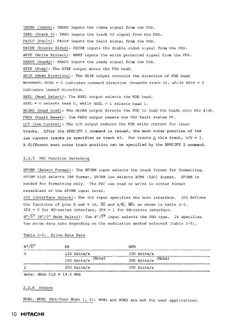
INDEX (Index): INDEX inputs the index signal from the FDD.TRKO (Track 0): TRKO inputs the track 00 signal from the FDD.FAULT (Fauit): FAULT inputs the fault signal from the FDD.DSIDE (Double Sided): DSIDE inputs the double sided signal from the FDD.WPRT (Write Protect): WPRT inputs the write protected signal from the FDD.READY (Ready): READY inputs the ready signal from the FDD.STEP (Step): The STEP output moves the FDD head.HDIR (Head Direction): The HDIR output controls the direction of FDD headmovement. HDIR = 0 indic'ates outward direction (towards track 0), while HDIR 1indicates inward direction.HSEL (Head Select): The HSEL output selects the FDD head.HSEL = 0 selects head 0, while HSEL = 1 selects head 1.HLOAD (Head Load): The HLOAD output directs the FDD to load the heads onto the disk.FRES (Fault Reset): The FRES output resets the FDD fault status FF.LCT (Low Current): The LCT output reduces the FDD write current for innertracks. After the SPECIFY 1 command is issued, the most outer position of thelow current tracks is specified as track 43. For tracks ~ this track, LCT = 1.A different most outer track position can be specified by the SPECIFY 2 command.2.2.5 FDC Function SwitchingSFORM (Select Format): The SFORM input selects the track format for formatting.SFORM high selects IBM format, SFORM low selects ECMA (ISO) format. SFORM isneeded for formatting only.regardless of the SFORM input level.The FDC can read or write in either formatIFS (Interface Select): The IFS input specifies the host interface.the functions of pins 8 and 9 (E, RD and R/W, WR) as shown in table 2-2.IFS 0 for 80-series interface, IFS = 1 for 68-series interface.8"/'.5'i (8"/5" Mode Select): The 8"/5" input selects the FDD type.IFS definesIt specifiesthe drive data rate depending on the modulation method selected (table 2-5).Table 2-5.Drive Data Rate8"/5" FM MFM0 125 kbits/s 250 kbits/s150 kbits/s (Note) 300 kbits/s (Note)1 250 kbits/s 500 kbits/sNote: When CLK19.2 MHz2.2.6 OthersNUMl, NUM2(Not-User Mode 1, 2): NUMI and NUM2 are not for user applications.10 HITACHI


