
Create successful ePaper yourself
Turn your PDF publications into a flip-book with our unique Google optimized e-Paper software.
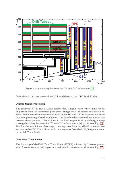
Figure 4.4: η boundary between the DT and CSC subsystems [22].forwards only the best two or three LCT candidates to the CSC Track Finder.Overlap Region ProcessingThe geometry of the muon system implies that a region exists where muon tracksoriginating from the interaction point pass through both the barrrel and endcap regions.To improve the measurements made by the DT and CSC subsystems and avoidduplicate processing of track candidates, it is therefore desirable to share informationbetween these systems. This is done at the local trigger level by defining a sharpcoverage boundary between the DT and CSC subsystems at |η| = 1.04 (see Fig. 4.4).To allow this redefinition of coverage, track segments from the MB2/2 muon stationsare sent to the CSC Track Finder and track segments from the ME1/3 region are sentto the DT Track Finder.Drift Tube Track FinderThe first stage of the Drift Tube Track Finder (DTTF) is formed by 72 sector processors.A sector covers a 30 ◦ region in φ and usually one detector wheel (see Fig. 4.5).41