EMI/EMP Filter Connectors Catalog - Glenair, Inc.
EMI/EMP Filter Connectors Catalog - Glenair, Inc.
EMI/EMP Filter Connectors Catalog - Glenair, Inc.
- No tags were found...

Create successful ePaper yourself
Turn your PDF publications into a flip-book with our unique Google optimized e-Paper software.
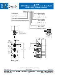
Composite ThermoplasticUser Adjustable Swing-Arm AssemblyTechnical Information<strong>EMI</strong> ShieldingAccessories45°Lacing String or HighTemperature Ty-StrapStaggerSolderSleevesFigure 490°Caution:Loosen saddle clamps toallow free cable movementbefore adjusting clamp toangular positions. Formthe cable into the desiredconfiguration, then tightenarms and secure thesaddle clamps.At the marked location, near the shieldsupport ring, wrap tape around wire bundlefor snug fit of shield support ring (Figure 1).Tape wrap is optional.You can then slide the overall braidfrom the wire bundle side over the shieldsupport ring, trimming braid ends and tuckingextra braid underneath itself for a cleanappearance.For pin connectors, slide the backshellforward, and hand tighten backshell toconnector. Then, evenly space shield pigtails(Figure 3) or solder sleeve pigtails (Figure4) around the shield support ring. Cut thepigtails so that the end of the pigtails slightlybeyond end of shield support ring.Bring the shield sock from backshell andcompletely cover the pigtails and supportring. Trim and fold the braid as shown inFigure 2. Lace tie the shield adjacent tosupport ring ends.Install <strong>Glenair</strong>'s Band-it ® band (600-052) between the lace ties onto the centerof the support ring as shown in Figure2. The hand banding tool (600-058) orpneumatic banding tool (600-067) is usedfor this banding process.Next, you can wrap the shield supportring assembly with high temperature tape.Place lacing cord, high temperature tape,or high temperature plastic Ty-Strapson the braid transition to the rear of thebackshell to secure the overbraid on wirebundle. If you wish, you can cover theoverbraid with 102-080 braid sock.Tighten the adapter to the connectorusing <strong>Glenair</strong> 600-091 composite hexcoupling torque wrench and related toolingaccessories to established torque values.Secure the strain relief saddle onto thewire bundle using TG69 soft jaw pliers.Torque the saddle screws to establishedvalues. You can use Teflon tape wrap orM85049/127 bushing strip as needed tocushion the braid sock under the saddleclamps.With these few steps, your Swing-Armstrain relief installation is complete!H© 2008 <strong>Glenair</strong>, <strong>Inc</strong>. CAGE Codes 06324Printed in U.S.A.GLENAIR, INC. • 1211 AIR WAY • GLENDALE, CA 91201-2497 • 818-247-6000 • FAX 818-500-9912www.glenair.comH-13E-Mail: sales@glenair.com