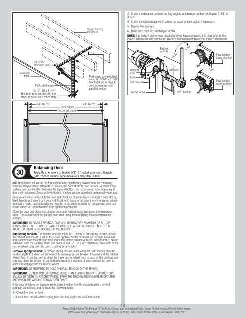
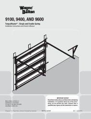
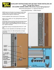
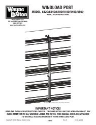
Sound framingmembers3.) Check the distance between the flag angles, which must be door width plus 3-3/8” to3-1/2”.4.) Check the counterbalance lift cables for equal tension, adjust if necessary.5.) Rewind the spring(s).6.) Make sure door isn’t rubbing on jambs.Note: If an idrive ® opener was installed and you have completed this step, refer to theidrive ® Installation Instructions and Owner’s Manual to complete your idrive ® installation.Horizontaltrack(3) 5/16”Bolts and nutsPerforated angle5/16”-18 x 1-1/4”Hex bolt must extend into thetrack to serve as a roller stopPerforated angle boltedusing (2) 5/16” x 1-5/8”hex head lag screws toceiling member andparallel to doorWindingshaftPawlEnd bracketRatchet wheelRatchetwrench3”extension5/8” SocketPawlPawl knob inlower positionPawl knob inupper position3/4” To 7/8” 3/4” To 7/8”Door edgesHorizontal tracks30Balancing DoorTools: Ratchet wrench, Socket: 5/8”, 3” Socket extension, Wrench:5/8”, (2) Vice clamps, Tape measure, Level, Step LadderNote: Windows will cause the top section to be significantly heavier than the remainingsections. <strong>Wayne</strong>-<strong>Dalton</strong> attempts to balance the door at the top and bottom. To prevent anysudden door acceleration between the top and bottom, we recommend motor operating alldoors with windows. Doors with windows in the top section should not be manually operated.Remove any vice clamps. <strong>Lift</strong> the door and check its balance. Adjust spring(s) if door lifts byitself (hard to pull down) or if door is difficult to lift (easy to pull down). Anytime spring adjustmentsare made, ratchet pawl knob must be in the upper position. An unbalanced door cancause idrive ® or <strong>TorqueMaster</strong> ® <strong>Plus</strong> operation problems.Close the door and place vice clamps onto both vertical tracks just above the third trackroller. This is to prevent the garage door from rising while adjusting the counterbalancespring(s).IMPORTANT: To adjust springs, only add or remove a maximum of 3/10 ofa turn (three teeth on the ratchet wheel) at a time. Both sides need to beadjusted equally on double spring doors.Add spring tension: The ratchet wheel is made of 10 teeth. To add spring tension, ensurethe ratchet and socket is set so that it will tighten counter clockwise on the right hand sideand clockwise on the left hand side. Place the ratchet wrench with 5/8” socket and 3” socketextension onto the winding shaft, pull down to add 3/10 of a turn. Watch as three teeth of theratchet wheel pass over the pawl, creating three “clicks”.Remove spring tension: To remove spring tension, place a regular 5/8” wrench onto thewinding shaft. Pull down on the wrench to relieve pressure between the pawl and the ratchetwheel. Push in on the pawl to allow the three ratchet wheel teeth to pass by the pawl, as youcarefully allow the wrench to be rotated upward by the spring tension, release the pawl toallow it to engage with the ratchet wheel.Important: Be prepared to hold the full tension of the spring.Important: Do not add or remove more than 1 spring turns (1 spring turnequals 10 teeth on ratchet wheel) from the recommended number of turnsshown on the winding spring turn chart.If the door still does not operate easily, lower the door into the closed position, unwindspring(s) completely, and recheck the following items:1.) Check the door for level.2.) Check the <strong>TorqueMaster</strong> ® spring tube and flag angles for level and plumb.14Please Do Not Return This Product To The Store. Contact your local <strong>Wayne</strong>-<strong>Dalton</strong> dealer. To find your local <strong>Wayne</strong>-<strong>Dalton</strong> dealer,refer to your local yellow pages business listings or go to the Find a Dealer section online at www.<strong>Wayne</strong>-<strong>Dalton</strong>.com
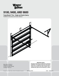
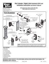
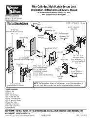
Optional Installation<strong>TorqueMaster</strong> ® <strong>Plus</strong> Reset InstructionsTools: Ratchet wrench, 5/8” Socket, 3” Socket extension, 5/8” Wrench,(2) Vice clamps, Step ladderIMPORTANT: The drawbar operator force settings must be adjusted accordingto the manufacturer’s instructions. Some lighter weight doors are designedto operate with a single counterbalance spring. If that counterbalance springbreaks and the drawbar operator’s force settings are not adjusted accordingto the manufacturer’s specifications, the drawbar operator may then have thecapability of lifting the door to the open position, despite the broken counterbalancespring. This scenario will cause the counterbalance lift cables to goslack and engage the <strong>TorqueMaster</strong> ® <strong>Plus</strong> safety system. If a person is unawareof the slack counterbalance lift cables and the engaged <strong>TorqueMaster</strong> ® <strong>Plus</strong>safety system and activates the misadjusted drawbar operator, damage willlikely occur to the door and drawbar operator. The potential also exists thatthe person activating the drawbar operator under this scenario could beseverely injured.WARNINGRead these instructions carefully before attempting to reset the<strong>TorqueMaster</strong> ® <strong>Plus</strong> system. If in question about any of the procedures,do not perform the work. Instead, have a qualified doorsystems technician reset the system.WARNINGTo avoid severe or fatal injury, do not stand or walk under amoving door, or permit anyone to stand or walk under an electricallyoperated door.This door is equipped with a <strong>TorqueMaster</strong> ® plus system, a safety feature which prevents thedoor from rapidly descending in case of spring failure or forceful manual operation. If the systemengages with the door in the open position, personal items that are left unattended in the garageor home are at risk to theft. To ensure the safekeeping of these items, close the garage door.Typical signs of an engaged system.Single spring system: Visually inspect the <strong>TorqueMaster</strong> ® <strong>Plus</strong> right hand end bracket to confirmthat the system has engaged (see illustration). If the system is engaged, then the door willnot close. If the drawbar operator force settings were properly set during the initial installation,the door will not open. If the drawbar operator can physically overcome the weight of the doorand lift it to the open position, then the counterbalance lift cables will be slack. If the system isengaged, DO NOT attempt to make the repairs. Instead, have a trained door system technicianmake the necessary repairs to counterbalance lift cables, spring assemblies and other hardware.Double spring system: Visually inspect the <strong>TorqueMaster</strong> ® <strong>Plus</strong> end brackets to confirmthat the system has engaged (see illustration). Door will open, but will not close. Door makes adistinct “clicking” noise upon being opened. If the system is engaged, carefully follow the resetinstructions below or refer to the reset tag (attached to right hand end bracket) to reset the<strong>TorqueMaster</strong> ® <strong>Plus</strong> system.Resetting an engaged <strong>TorqueMaster</strong> ® <strong>Plus</strong> double spring system only:1. First, locate and visually inspect the <strong>TorqueMaster</strong> ® plus end brackets to confirm that thesystem has engaged (see illustration).2. Disengage the drawbar operator (if installed) by pulling or placing the emergency disconnectin the manually operated position.3. With assistance, raise the door to the fully open position.4. Place vice clamps onto both vertical tracks just below the bottom track roller on both sides.5. Now is a good time to remove vehicles or personal items from garage to provide clear accessto end brackets.6. Flip the ratchet pawl knob on both end brackets to the upper position (see illustration).7. Raise door 2”-3” and then lower door. Repeat this process until the system resets (seedisengaged system illustrations).IMPORTANT: Be prepared to support the total weight of the door.8. Cautiously remove the vice clamps from the vertical tracks. With assistance lower door.Checking springs for tension:9. Starting on the right hand side, place a ratchet wrench, 5/8” socket and a 3” extension on the<strong>TorqueMaster</strong> ® <strong>Plus</strong> winding shaft (see illustration). Ensure ratchet is set so that it will tightencounter clockwise on the right hand side, and clockwise on the left hand side. If tension is present,remove the ratchet and check the left hand side. If spring(s) have tension, the door will needto be balanced; refer to step, Balancing Door, to do this. If no spring tension is present, contact aqualified trained door system technician to replace the spring(s).IMPORTANT: To avoid possible injury, have a trained door systems technicianmake adjustments/ repairs to counterbalance lift cables, spring assembliesand other hardware.SideviewBelowviewRatchetpawlDrum wrap(if applicable)WindingshaftPawlDrumpawlEnd bracketRatchet wheel<strong>TorqueMaster</strong> ® <strong>Plus</strong>reset instructions tagCabledrumNo space between drum pawl andcable drum indicates engagementRatchetwrench3”extensionDoor Arm HookupTools: Needle nose pliers5/8” socketDrumpawlCabledrumSpace between drum pawl and cabledrum indicates non-engagementPawlPawl knob inlower positionPawl knob inupper positionAlign hole in the door arm with holes in drawbar operator bracket tabs, as shown. Insert 5/16”x 1-1/4” clevis pin, making sure hole in clevis pin is outside of second tab of drawbar operatorbracket. Insert hairpin cotter into clevis pin hole and spread hairpin cotter to secure assembly,as shown.5/16”x 1-1/4”Clevis pinDrawbaroperator bracketCotterpinDrawbar operatorbracket tabsDoor armInside LockTools: Power drill, 7/16” Socket driver, Tape measureClevis pinSpread cotter pinInstall the inside lock on the second section of the door. Secure the lock to the section with (4)1/4”-20 x 11/16” self drilling screws. Square the lock assembly with the door section, and alignwith the square hole in the vertical track. The inside lock should be spaced approximately 1/8”away from the section edge.Important: Inside lock(s) must be removed or made inoperative in the unlockedposition if an operator is installed on this door.Second section 1/8”Inside lockEnd capSquare hole invertical track(4) 1/4”-20 x 11/16”Self drilling screws15Please Do Not Return This Product To The Store. Contact your local <strong>Wayne</strong>-<strong>Dalton</strong> dealer. To find your local <strong>Wayne</strong>-<strong>Dalton</strong> dealer,refer to your local yellow pages business listings or go to the Find a Dealer section online at www.<strong>Wayne</strong>-<strong>Dalton</strong>.com