Fusion FH-100 and FHR-100 - Vinten Radamec
Fusion FH-100 and FHR-100 - Vinten Radamec
Fusion FH-100 and FHR-100 - Vinten Radamec

You also want an ePaper? Increase the reach of your titles
YUMPU automatically turns print PDFs into web optimized ePapers that Google loves.
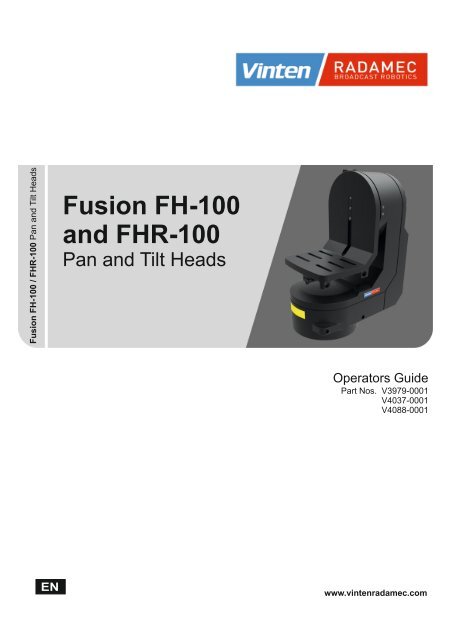
<strong>Fusion</strong> <strong>FH</strong>-<strong>100</strong> / <strong>FH</strong>R-<strong>100</strong> Pan <strong>and</strong> Tilt Heads<br />
<strong>Fusion</strong> <strong>FH</strong>-<strong>100</strong><br />
<strong>and</strong> <strong>FH</strong>R-<strong>100</strong><br />
Pan <strong>and</strong> Tilt Heads<br />
Operators Guide<br />
Part Nos. V3979-0001<br />
V4037-0001<br />
V4088-0001<br />
www.vintenradamec.com
<strong>Fusion</strong><br />
<strong>FH</strong>-<strong>100</strong> <strong>and</strong> <strong>FH</strong>R-<strong>100</strong><br />
Manual <strong>and</strong> Robotic<br />
Pan <strong>and</strong> Tilt Heads<br />
Operators Guide
Publication Part No. V3979-4980<br />
Issue 4<br />
November 2011<br />
Published by<br />
Vitec Group Videocom Division<br />
Technical Publications Department<br />
William <strong>Vinten</strong> Building<br />
Western Way<br />
Bury St Edmunds<br />
Suffolk IP33 3TB<br />
UK<br />
Email: technical.publications@vitecgroup.com<br />
Copyright © 2011 The Vitec Group plc<br />
All rights reserved throughout the world. No part of this<br />
document may be stored in a retrieval system, transmitted,<br />
copied or reproduced in any way, including, but not limited<br />
to, photocopy, photograph, magnetic or other record<br />
without the prior agreement <strong>and</strong> permission in writing of<br />
the Vitec Group plc.<br />
Trademark acknowledgements<br />
<strong>Vinten</strong> <strong>Radamec</strong> Broadcast Robotics, <strong>Vinten</strong> <strong>and</strong><br />
Quickfix ® are registered trademarks of the Vitec Group plc.<br />
Disclaimer<br />
Camera Dynamics Limited reserves the right, without notice,<br />
to revise this documentation <strong>and</strong> make changes in content<br />
from time to time without obligation to provide notification of<br />
such revision or change. Revised documentation may be<br />
obtainable from <strong>Vinten</strong> <strong>Radamec</strong> or downloadable from the<br />
website (www.vintenradamec.com). Camera Dynamics<br />
Limited reserves the right, without notice, to make changes<br />
in equipment design or performance as progress in<br />
engineering, manufacturing or technology may warrant.
Safety – read this first<br />
Underst<strong>and</strong>ing these instructions<br />
English<br />
The original instructions presented<br />
in this operators guide were written<br />
in English, <strong>and</strong> subsequently<br />
translated into other languages. If<br />
you are unable to underst<strong>and</strong> these<br />
instructions, contact <strong>Vinten</strong> or your<br />
distributor to obtain a translation of<br />
the original instructions (EU<br />
Countries).<br />
БЪЛГАРСКИ<br />
Оригиналните инструкции,<br />
представени в настоящото<br />
ръководство на производителя,<br />
бяха написани на английски език,<br />
а след това - преведени на други<br />
езици. Ако не разбирате тези<br />
езици, свържете се с <strong>Vinten</strong> или с<br />
Вашия дистрибутор, за да<br />
получите оригиналните<br />
инструкции (за страните от<br />
Европейския съюз).<br />
Česky<br />
Dansk<br />
Deutsch<br />
Eesti<br />
Pokyny uvedené v této operátorské<br />
příručce byly původně napsány<br />
anglicky a následně byly přelo_eny<br />
do ostatních jazyků. Nerozumíte-li<br />
těmto pokynům, kontaktujte<br />
společnost <strong>Vinten</strong> nebo svého<br />
distributora, abyste získali překlad<br />
originálních pokynů (členské státy<br />
EU).<br />
De originale instruktioner, der<br />
præsenteres i denne<br />
betjeningsvejledning, er skrevet på<br />
engelsk og derefter oversat til<br />
<strong>and</strong>re sprog. Hvis du ikke forstår<br />
disse instruktioner bedes du<br />
kontakte <strong>Vinten</strong> eller vor forh<strong>and</strong>ler<br />
for at få en oversættelse af de<br />
originale instruktioner (EU-l<strong>and</strong>e).<br />
Die Originalanleitung in diesem<br />
Bedienungsh<strong>and</strong>buch wurde auf<br />
Englisch verfasst und anschließend<br />
in <strong>and</strong>ere Sprachen übersetzt. Bei<br />
Verständnisproblemen in einer der<br />
übersetzten Sprachen kontaktieren<br />
Sie bitte <strong>Vinten</strong> oder Ihren<br />
Fachhändler; dort erhalten Sie eine<br />
Übersetzung der ursprünglichen<br />
Anleitung (EU-Staaten).<br />
Käesoleva kasutajajuhendi algtekst<br />
on koostatud inglise keeles ning<br />
seejärel tõlgitud teistesse<br />
keeltesse. Kui juhend osutub teie<br />
jaoks arusaamatuks, võtke juhendi<br />
emakeelse tõlke hankimiseks<br />
ühendust <strong>Vinten</strong>i või kohaliku<br />
esindajaga (Euroopa Liidu riigid).<br />
Ελληνικά<br />
Español<br />
Français<br />
Gaeilge<br />
Italiano<br />
Latviešu<br />
Operators guide<br />
Οι αρχικές οδηγίες αυτού του<br />
οδηγού για το χειριστή<br />
συντάχθηκαν στα Αγγλικά και<br />
μεταφράστηκαν στη συνέχεια σε<br />
άλλες γλώσσες. Εάν δυσκολεύεστε<br />
να καταλάβετε αυτές τις οδηγίες,<br />
επικοινωνήστε με τη <strong>Vinten</strong> ή το<br />
διανομέα σας για να λάβετε μια<br />
μετάφραση των αρχικών οδηγιών<br />
(Χώρες ΕΕ).<br />
Las instrucciones originales que se<br />
indican en esta guía del operador<br />
se han redactado en inglés y<br />
posteriormente se han traducido a<br />
otros idiomas. Si no entiende estas<br />
instrucciones, póngase en contacto<br />
con <strong>Vinten</strong> o con su distribuidor<br />
para obtener una traducción de las<br />
instrucciones originales (para<br />
países de la UE).<br />
Les instructions originales<br />
présentées dans ce guide<br />
d'utilisation ont été écrites en<br />
anglais puis traduites dans d'autres<br />
langues. Si vous ne comprenez pas<br />
ces instructions, contactez <strong>Vinten</strong><br />
ou votre revendeur pour obtenir<br />
une traduction des instructions<br />
originales (pour les pays de l'UE).<br />
Scríobhadh na treoracha bunaidh<br />
don treoirleabhar oibritheora seo as<br />
Béarla, agus aistríodh iad go<br />
teangacha eile ina dhiaidh sin.<br />
Mura bhfuil tú in ann na treoracha<br />
seo a thuiscint, téigh i dteagmháil le<br />
<strong>Vinten</strong> nó le do dháileoir, chun<br />
aistriúchán de na treoracha<br />
bunaidh a fháil (Tíortha an AE).<br />
Le istruzioni originali presentate in<br />
questa guida per l'operatore sono<br />
in lingua inglese e<br />
successivamente tradotte nelle<br />
altre lingue. Qualora le istruzioni<br />
non fossero disponibili nella lingua<br />
desiderata, potete contattare<br />
<strong>Vinten</strong> o il vostro distributore per<br />
ricevere la traduzione delle<br />
istruzioni originali (Paesi UE).<br />
Šajā operatora rokasgrāmatā<br />
iekļautie norādījumi sākotnēji tika<br />
sarakstīti angļu valodā un pēc tam<br />
pārtulkoti citās valodās. Ja<br />
nesaprotat šos norādījumus<br />
svešvalodā, sazinieties ar <strong>Vinten</strong><br />
vai tirgotāju, lai saņemtu<br />
norādījumu tulkojumu (kādā no ES<br />
dalībvalstu valodām).<br />
3
<strong>Fusion</strong> <strong>FH</strong>-<strong>100</strong> <strong>and</strong> <strong>FH</strong>R-<strong>100</strong> pan <strong>and</strong> tilt heads<br />
Lietuvių<br />
Magyar<br />
Malti<br />
4<br />
Šiame operatoriaus vadove<br />
pristatomos pirminės instrukcijos<br />
parašytos anglų kalba ir vėliau<br />
išverstos į kitas kalbas. Jei šių<br />
instrukcijų nesuprantate, susisiekite<br />
su „<strong>Vinten</strong>“ arba savo platintoju<br />
ir gaukite pirminių instrukcijų<br />
vertimą (ES šalies kalba).<br />
A kezeloi útmutatóban található<br />
utasítások angol nyelven íródtak,<br />
és utólag fordították azokat más<br />
nyelvekre. Ha nem érti ezen<br />
utasításokat, kérjük, vegye fel a<br />
kapcsolatot a <strong>Vinten</strong>nel vagy a<br />
helyi képviselettel, és igényelje az<br />
eredeti utasítások fordítását (EU<br />
országok).<br />
L-istruzzjonijiet originali<br />
ippreżentati f'din il-gwida ta'<br />
operaturi kienu miktuba bl-Ingliż, u<br />
sussegwentement maqluba fllingwi<br />
ohra. Jekk ma tistax tifhem<br />
dawn l-istruzzjonijiet, ikkuntattja lil<br />
<strong>Vinten</strong> jew id-distributur tieghek<br />
biex tikseb traduzzjoni ta' listruzzjonijiet<br />
originali (Pajjiżi ta'<br />
UE).<br />
Nederl<strong>and</strong>s<br />
De oorspronkelijke instructies in<br />
deze bedieningsh<strong>and</strong>leiding zijn<br />
geschreven in het Engels en<br />
vervolgens in <strong>and</strong>ere talen<br />
vertaald. Als het onmogelijk is deze<br />
instructies te begrijpen, neemt u<br />
contact op met <strong>Vinten</strong> of met uw<br />
distributeur om een vertaling te<br />
bemachtigen van de<br />
oorspronkelijke instructies (EGl<strong>and</strong>en).<br />
Polski<br />
Português<br />
Oryginalne instrukcje<br />
zamieszczone w niniejszym<br />
podręczniku operatora zostały<br />
napisane w języku angielskim, a<br />
następnie przetłumaczone na inne<br />
języki. Jeśli nie rozumieją Państwo<br />
tych instrukcji, prosimy<br />
skontaktować się z siedzibą lub<br />
dystrybutorem <strong>Vinten</strong>, aby uzyskać<br />
tłumaczenie oryginalnych instrukcji<br />
(kraje UE).<br />
As instruções originais<br />
apresentadas no guia do operador<br />
foram escritas em Inglês e<br />
traduzidas para outros idiomas. Se<br />
não conseguir compreender estas<br />
instruções contacte a <strong>Vinten</strong> ou o<br />
seu distribuidor para obter a<br />
tradução das instruções originais<br />
(Países da UE).<br />
Română<br />
Slovensky<br />
Instrucţiunile originale prezentate<br />
în acest ghid pentru operatori au<br />
fost scrise în limba engleză, şi<br />
traduse ulterior în alte limbi. În<br />
cazul în care nu înţelegeţi aceste<br />
instrucţiuni, contactaţi <strong>Vinten</strong> sau<br />
distribuitorul dumneavoastră pentru<br />
a obţine o traducere a<br />
instrucţiunilor originale (Ţările UE).<br />
Pôvodné pokyny, uvedené v tomto<br />
návode na obsluhu, boli napísané v<br />
anglictine a následne preložené do<br />
iných jazykov. Ak nerozumiete<br />
týmto pokynom, obrátte sa na<br />
spolocnost <strong>Vinten</strong> alebo vášho<br />
distribútora, aby vám zaslal preklad<br />
originálnych pokynov (krajiny EÚ).<br />
Slovenščina<br />
Originalno besedilo teh navodil za<br />
uporabo je bilo napisano v<br />
angleščini in prevedeno v ostale<br />
jezike. Če ne razumete teh navodil,<br />
se obrnite na podjetje <strong>Vinten</strong> ali<br />
lokalnega zastopnika, ki vam bo<br />
posredoval originalna navodila<br />
(velja za dr_ave EU).<br />
Suomi<br />
Svenska<br />
Tähän käyttäjän oppaaseen<br />
sisältyvät ohjeet on kirjoitettu alun<br />
perin englanniksi ja käännetty<br />
sitten muille kielille. Ellet ymmärrä<br />
näitä ohjeita, ota yhteyttä <strong>Vinten</strong>iin<br />
tai jälleenmyyjään ja pyydä<br />
alkuperäisten ohjeiden käännöstä<br />
(EU-maat).<br />
Instruktionerna i denna h<strong>and</strong>bok<br />
skrevs ursprungligen på engelska<br />
och har sedan översatts till flera<br />
språk. Om du inte förstår dessa<br />
instruktioner, kontakta <strong>Vinten</strong> eller<br />
din återförsäljare för en ny<br />
översättning av originalinstruktionerna<br />
(EU-länder).
Safety instructions<br />
Please read this Operators Guide carefully<br />
before attempting to operate the product.<br />
Retain this guide for future reference.<br />
Safety when working with the<br />
product<br />
!<br />
Take heed of warnings <strong>and</strong><br />
instructions<br />
You should read all of the safety<br />
instructions in this Operators<br />
Guide before attempting to<br />
operate the equipment. Adhere<br />
to all warnings in this guide <strong>and</strong><br />
on the equipment. Do not attempt<br />
to operate this equipment, if you<br />
do not underst<strong>and</strong> how to<br />
operate it.<br />
Power sources<br />
Connect the product to a power<br />
supply of the type <strong>and</strong> voltage<br />
rating described in the ‘Technical<br />
data’ section of this Operators<br />
Guide or as marked on the<br />
product.<br />
For an emergency power-down,<br />
ensure all personnel are aware of<br />
the location of the power switch<br />
on the product <strong>and</strong> associated<br />
equipment <strong>and</strong> power supplies.<br />
Servicing<br />
Do not attempt to service this<br />
product. Opening <strong>and</strong> removing<br />
covers may expose you to<br />
dangerous voltages or other<br />
hazards. Refer all servicing to<br />
trained <strong>and</strong> competent personnel.<br />
Contact <strong>Vinten</strong> <strong>Radamec</strong> to<br />
arrange servicing of this product.<br />
OFF<br />
Operators guide<br />
Water, moisture <strong>and</strong> dust<br />
Protect the product from water,<br />
moisture <strong>and</strong> dust. The presence<br />
of electricity near water can be<br />
dangerous. Do not use the<br />
product near water <strong>and</strong> take care<br />
that liquids are not spilled onto the<br />
equipment.<br />
Operating environment<br />
The product should not be used<br />
outside the operating<br />
temperature limits. To prevent risk<br />
of overheating, ventilate the<br />
product correctly. Refer to the<br />
‘Technical data’ section of this<br />
guide for the operating limits for<br />
the product.<br />
Connections<br />
Turn OFF before connecting or<br />
disconnecting any equipment or<br />
making any adjustments to the<br />
camera or associated equipment.<br />
Safety when working with robotic<br />
equipment<br />
In normal operation, remote-controlled<br />
equipment can move suddenly <strong>and</strong> without<br />
warning. Since audible warnings are not<br />
suitable for use within the studio environment,<br />
it is recommended that only trained personnel<br />
be allowed to work in the active areas where<br />
remote controlled heads <strong>and</strong> pedestals are<br />
located. The safe operating zone is a<br />
minimum of 1 m (3 ft). Do not operate robotic<br />
equipment, if you cannot see it.<br />
5
<strong>Fusion</strong> <strong>FH</strong>-<strong>100</strong> <strong>and</strong> <strong>FH</strong>R-<strong>100</strong> pan <strong>and</strong> tilt heads<br />
Warning symbols<br />
WARNING!<br />
Where there is a risk of personal<br />
! injury or injury to others,<br />
comments appear supported by<br />
the warning triangle symbol.<br />
Where there is a risk of damage to the<br />
product, associated equipment, process or<br />
surroundings, comments appear preceded by<br />
the word ‘CAUTION!’.<br />
CAUTION<br />
finger trap<br />
Usage<br />
6<br />
!<br />
ELECTRIC SHOCK<br />
Where there is a risk of electric<br />
shock, comments appear<br />
supported by the hazardous<br />
voltage warning triangle symbol.<br />
FINGER TRAP<br />
Where there is a risk of trapping<br />
fingers within parts of the product<br />
or other equipment mounted to<br />
the product, comments appear<br />
supported by the finger trap<br />
symbol.<br />
READ INSTRUCTIONS<br />
On encountering the warning<br />
triangle <strong>and</strong> open book symbols it<br />
is important that you read this<br />
operators guide before using this<br />
product or attempting any<br />
adjustment or repair.<br />
These products are designed for use within<br />
television studios to support <strong>and</strong> balance a<br />
camera <strong>and</strong> other ancillary equipment with a<br />
total weight of up to 45 kg (<strong>100</strong> lb). The <strong>Fusion</strong><br />
<strong>FH</strong>-<strong>100</strong> <strong>and</strong> <strong>FH</strong>-<strong>100</strong> VR pan/tilt heads allow<br />
operators to robotically or manually control<br />
camera pan <strong>and</strong> tilt movements. The <strong>Fusion</strong><br />
<strong>FH</strong>R-<strong>100</strong> pan/tilt head can only be operated in<br />
robotic mode.<br />
The total payload must not be exceeded.<br />
The product is intended for use by television<br />
camera operators trained to use <strong>Vinten</strong><br />
<strong>Radamec</strong> robotic equipment.<br />
WARNING!<br />
1. DO NOT attempt to use<br />
this product if you do not<br />
underst<strong>and</strong> how to<br />
operate it.<br />
2. DO NOT use this product<br />
for any other purpose<br />
than that specified in this<br />
Usage statement.<br />
3. Maintenance beyond that<br />
detailed in this Operators<br />
Guide must be performed<br />
by competent personnel.<br />
Disposing of used electrical<br />
<strong>and</strong> electronic equipment<br />
When you see this symbol on<br />
a <strong>Vinten</strong> <strong>Radamec</strong> product it<br />
indicates that this product<br />
must not be disposed of with<br />
household waste. In some<br />
countries or EC regions,<br />
separate collection systems<br />
have been set up to h<strong>and</strong>le electrical <strong>and</strong><br />
electronic waste products. This product must<br />
be disposed of at a collection point for the<br />
recycling of such equipment.<br />
By ensuring this product is disposed of<br />
correctly, you will help protect human health<br />
<strong>and</strong> conserve natural resources <strong>and</strong> the<br />
environment. For more information about<br />
disposing of this product, visit<br />
www.vintenradamec.com.
Declaration of Conformity<br />
In respect of the following equipment manufactured by Camera Dynamics Limited:<br />
Model Part no. Description<br />
in accordance with the following European Directives:<br />
EU Low-Voltage Directive 2004/95/EC<br />
EU EMC Directive 89/336/EEC<br />
by application of the following Harmonised St<strong>and</strong>ards:<br />
Other certification<br />
In addition, this product conforms to the following st<strong>and</strong>ards:<br />
Operators guide<br />
<strong>Fusion</strong> <strong>FH</strong>-<strong>100</strong> V3979-0001 Manual <strong>and</strong> robotic pan <strong>and</strong> tilt head<br />
<strong>Fusion</strong> <strong>FH</strong>-<strong>100</strong> VR V4037-0001 VR-enabled manual <strong>and</strong> robotic pan<br />
<strong>and</strong> tilt head<br />
<strong>Fusion</strong> <strong>FH</strong>R-<strong>100</strong> V4088-0001 Robotic pan <strong>and</strong> tilt head<br />
EN60065 - 1:2002 Audio, video <strong>and</strong> similar electronic apparatus – Safety<br />
requirements<br />
EN55103-1:1996 EMC – Product family st<strong>and</strong>ard for audio, video, audio-visual<br />
<strong>and</strong> entertainment lighting control apparatus for professional<br />
use. Part 1: Emission.<br />
EN55103-2:1997 EMC – Product family st<strong>and</strong>ard for audio, video, audio-visual<br />
<strong>and</strong> entertainment lighting control apparatus for professional<br />
use. Part 2: Immunity<br />
EN6<strong>100</strong>0-4-4:2004 EMC – Part 4-4: Testing <strong>and</strong> measurements techniques –<br />
Electrical fast transient/burst immunity test.<br />
FCC C.F.R., Title 47 (Telecommunications), Part 15.b, 2006 -<br />
Equipment authorization of unintentional radiators<br />
7
<strong>Fusion</strong> <strong>FH</strong>-<strong>100</strong> <strong>and</strong> <strong>FH</strong>R-<strong>100</strong> pan <strong>and</strong> tilt heads<br />
Technical data<br />
Physical data<br />
Weight . . . . . . . . . . . . . . . . . . . . . . . . . . . . . . . . . . . . . . . . . . . . . . . . . . . . . . . . .24.5 kg (54 lb)<br />
Maximum payload . . . . . . . . . . . . . . . . . . . . . . . . . . . . . . . . . . . . . . . . . . . . . . . . 55 kg (121 lb)<br />
Height to wedge adaptor<br />
mounting face. . . . . . . . . . . . . . . . . . . . . . . . . . . . . . . . . . . . . . . . .257–366 mm (10.1–14.4 in.)<br />
Height . . . . . . . . . . . . . . . . . . . . . . . . . . . . . . . . . . . . . . . . . . . . . . . . . . . . . . . 519 mm (20.4 in.)<br />
Length . . . . . . . . . . . . . . . . . . . . . . . . . . . . . . . . . . . . . . . . . . . . . . . . . . . . . . . 225 mm (8.9 in.)<br />
Width . . . . . . . . . . . . . . . . . . . . . . . . . . . . . . . . . . . . . . . . . . . . . . . . . . . . . . . 404 mm (15.9 in.)<br />
Operating data<br />
Operating temperature range . . . . . . . . . . . . . . . . . . . . . . . . . .0°C to +50°C (+32°F to +122°F)<br />
Motor noise. . . . . . . . . . . . . . . . . . . . . . . . . . . . . . . . . . . . . . . . . . . . . . . . . . . . . . . . . . . Minimal<br />
Tilt range. . . . . . . . . . . . . . . . . . . . . . . . . . . . . . . . . . . . . . . . . . . . . . . . . . . . . . . . . . . . . . . ±90°<br />
Pan range . . . . . . . . . . . . . . . . . . . . . . . . . . . . . . . . . . . . . . . . . . . . . . . . . . . . . . . . . . . . . 359°<br />
Angular velocity (max) . . . . . . . . . . . . . . . . . . . . . . . . . . . . . . . . . . . . . . . . . . . . . . . . . . . . 60°/s<br />
Angular velocity (min). . . . . . . . . . . . . . . . . . . . . . . . . . . . . . . . . . . . . . . . . . . . . . . . . . . . .0.1°/s<br />
Angular acceleration. . . . . . . . . . . . . . . . . . . . . . . . . . . . . . . . . . . . . . . . . . . . . . . . . . . . . 120°/s<br />
Response time . . . . . . . . . . . . . . . . . . . . . . . . . . . . . . . . . . . . . . . . . . . . . . . . . . . . 4x per frame<br />
Accuracy. . . . . . . . . . . . . . . . . . . . . . . . . . . . . . . . . . . . . . . . . . . . . . . . . . . . . . . . . 3 min. of arc<br />
Repeatability. . . . . . . . . . . . . . . . . . . . . . . . . . . . . . . . . . . . . . . . . . . . . . . . 3 min. of arc (0.05°)<br />
Robotic operation . . . . . . . . . . . . . . . . . . . . . . . . . . . . . . . . . . . . . . . . . . . . . . . . . . . . . . . . . Yes<br />
Manual operation . . . . . . . . . . . . . . . . . . . . . . . . . . . . . . . . . . . . . . . . . . . . . . . . . . . . . . . . .Yes*<br />
*except <strong>FH</strong>R-<strong>100</strong><br />
Electrical data<br />
Power consumption (peak). . . . . . . . . . . . . . . . . . . . . . . . . . . . . . . . . . . . . . . . . . . . . . . . 250 W<br />
Power input . . . . . . . . . . . . . . . . . . . . . . . . . . . . . . . . . . Autoranging 110–240V AC, 50–60 Hz<br />
System fuse . . . . . . . . . . . . . . . . . . . . . . . . . . . . . . . . . . . . . . . . . . . . . . . . . . . . . . . . . . . T6.3A<br />
Mountings<br />
Pedestal/tripod fixing . . . . . . . . . . . . . . . . . . . . . . . . . . . . . . . . . . . . . . . . . . Four-hole flat base<br />
Quickfix base . . . . . . . . . . . . . . . . . . . . . . . . . . . . . . . . . . . . . . . . .Heavy-duty Quickfix adaptor<br />
8<br />
WARNING!<br />
This product has basic insulation only (Class 1). The product requires an<br />
earth connection (US: GND).<br />
Technical specifications are subject to change without notice.
Contents<br />
Operators guide<br />
Page<br />
Safety – read this first . . . . . . . . . . . . . . . . . . . . . . . . . . . . . . . . . . . . . . . . . . . . . . 3<br />
Safety instructions . . . . . . . . . . . . . . . . . . . . . . . . . . . . . . . . . . . . . . . . . . . . . . . . . . . . . . . 5<br />
Safety when working with the product . . . . . . . . . . . . . . . . . . . . . . . . . . . . . . . . . . . . . 5<br />
Safety when working with robotic equipment . . . . . . . . . . . . . . . . . . . . . . . . . . . . . . . 5<br />
Warning symbols . . . . . . . . . . . . . . . . . . . . . . . . . . . . . . . . . . . . . . . . . . . . . . . . . . . . . . . . 6<br />
Usage. . . . . . . . . . . . . . . . . . . . . . . . . . . . . . . . . . . . . . . . . . . . . . . . . . . . . . . . . . . . . . . . . 6<br />
Disposing of used electrical <strong>and</strong> electronic equipment . . . . . . . . . . . . . . . . . . . . . . . . . . . 6<br />
Declaration of Conformity . . . . . . . . . . . . . . . . . . . . . . . . . . . . . . . . . . . . . . . . . . . 7<br />
Other certification. . . . . . . . . . . . . . . . . . . . . . . . . . . . . . . . . . . . . . . . . . . . . . . . . . . . . . . . 7<br />
Technical data. . . . . . . . . . . . . . . . . . . . . . . . . . . . . . . . . . . . . . . . . . . . . . . . . . . . . 8<br />
Components <strong>and</strong> connections . . . . . . . . . . . . . . . . . . . . . . . . . . . . . . . . . . . . . . 11<br />
Introduction <strong>and</strong> description. . . . . . . . . . . . . . . . . . . . . . . . . . . . . . . . . . . . . . . . 14<br />
<strong>FH</strong>-<strong>100</strong> manual/robotic head . . . . . . . . . . . . . . . . . . . . . . . . . . . . . . . . . . . . . . . . . . . . . . 14<br />
<strong>FH</strong>-<strong>100</strong> VR manual/robotic head with VR output . . . . . . . . . . . . . . . . . . . . . . . . . . . . . . . 14<br />
<strong>FH</strong>R-<strong>100</strong> robotic head . . . . . . . . . . . . . . . . . . . . . . . . . . . . . . . . . . . . . . . . . . . . . . . . . . . 14<br />
Lens drive . . . . . . . . . . . . . . . . . . . . . . . . . . . . . . . . . . . . . . . . . . . . . . . . . . . . . . . . . . . . 14<br />
Installation. . . . . . . . . . . . . . . . . . . . . . . . . . . . . . . . . . . . . . . . . . . . . . . . . . . . . . . 15<br />
Unpacking the head . . . . . . . . . . . . . . . . . . . . . . . . . . . . . . . . . . . . . . . . . . . . . . . . . . . . . 15<br />
Accessories . . . . . . . . . . . . . . . . . . . . . . . . . . . . . . . . . . . . . . . . . . . . . . . . . . . . . . . . 16<br />
Mounting the head . . . . . . . . . . . . . . . . . . . . . . . . . . . . . . . . . . . . . . . . . . . . . . . . . . . . . . 16<br />
Mounting the head onto a Quickfix® adaptor . . . . . . . . . . . . . . . . . . . . . . . . . . . . . . 17<br />
Mounting the camera <strong>and</strong> payload. . . . . . . . . . . . . . . . . . . . . . . . . . . . . . . . . . . . . . . . . . 18<br />
Fitting the camera . . . . . . . . . . . . . . . . . . . . . . . . . . . . . . . . . . . . . . . . . . . . . . . . . . . 18<br />
Mounting the payload . . . . . . . . . . . . . . . . . . . . . . . . . . . . . . . . . . . . . . . . . . . . . . . . 19<br />
Attaching the FVR box to the head (<strong>FH</strong>-<strong>100</strong> VR only). . . . . . . . . . . . . . . . . . . . . . . . 19<br />
Electrical connections . . . . . . . . . . . . . . . . . . . . . . . . . . . . . . . . . . . . . . . . . . . . . . . . . . . 20<br />
Power <strong>and</strong> Ethernet connections. . . . . . . . . . . . . . . . . . . . . . . . . . . . . . . . . . . . . . . . 20<br />
Camera lens cabling . . . . . . . . . . . . . . . . . . . . . . . . . . . . . . . . . . . . . . . . . . . . . . . . . 23<br />
Connecting the FVR box to the <strong>FH</strong>-<strong>100</strong> VR head . . . . . . . . . . . . . . . . . . . . . . . . . . . 24<br />
Balancing the head <strong>and</strong> payload . . . . . . . . . . . . . . . . . . . . . . . . . . . . . . . . . . . . . . . . . . . 25<br />
Setting fore <strong>and</strong> aft balance. . . . . . . . . . . . . . . . . . . . . . . . . . . . . . . . . . . . . . . . . . . . 25<br />
Centre of Gravity (C of G) height adjustment . . . . . . . . . . . . . . . . . . . . . . . . . . . . . . 26<br />
Configuration . . . . . . . . . . . . . . . . . . . . . . . . . . . . . . . . . . . . . . . . . . . . . . . . . . . . 27<br />
Setting pan <strong>and</strong> tilt movement limits . . . . . . . . . . . . . . . . . . . . . . . . . . . . . . . . . . . . . . . . 27<br />
Setting the camera number . . . . . . . . . . . . . . . . . . . . . . . . . . . . . . . . . . . . . . . . . . . . . . . 29<br />
9
<strong>Fusion</strong> <strong>FH</strong>-<strong>100</strong> <strong>and</strong> <strong>FH</strong>R-<strong>100</strong> pan <strong>and</strong> tilt heads<br />
Operation . . . . . . . . . . . . . . . . . . . . . . . . . . . . . . . . . . . . . . . . . . . . . . . . . . . . . . . 30<br />
Powering up . . . . . . . . . . . . . . . . . . . . . . . . . . . . . . . . . . . . . . . . . . . . . . . . . . . . . . . . . . . 30<br />
Locking the camera cradle. . . . . . . . . . . . . . . . . . . . . . . . . . . . . . . . . . . . . . . . . . . . . . . . 30<br />
Operating the <strong>FH</strong>-<strong>100</strong> head . . . . . . . . . . . . . . . . . . . . . . . . . . . . . . . . . . . . . . . . . . . . . . . 31<br />
Switching the <strong>FH</strong>-<strong>100</strong> head to robotic mode . . . . . . . . . . . . . . . . . . . . . . . . . . . . . . . 31<br />
Switching the <strong>FH</strong>-<strong>100</strong> head to manual mode . . . . . . . . . . . . . . . . . . . . . . . . . . . . . . 33<br />
Adjusting the pan <strong>and</strong> tilt drag . . . . . . . . . . . . . . . . . . . . . . . . . . . . . . . . . . . . . . . . . . 34<br />
Operating the <strong>FH</strong>-<strong>100</strong> VR head . . . . . . . . . . . . . . . . . . . . . . . . . . . . . . . . . . . . . . . . . . . . 35<br />
Switching the <strong>FH</strong>-<strong>100</strong> VR head from robotic to VR manual mode . . . . . . . . . . . . . . 35<br />
Switching the <strong>FH</strong>-<strong>100</strong> VR head from VR manual mode to robotic mode . . . . . . . . . 35<br />
Switching the <strong>FH</strong>-<strong>100</strong> VR head to full manual mode. . . . . . . . . . . . . . . . . . . . . . . . . 36<br />
Maintenance . . . . . . . . . . . . . . . . . . . . . . . . . . . . . . . . . . . . . . . . . . . . . . . . . . . . . 37<br />
Checking balance . . . . . . . . . . . . . . . . . . . . . . . . . . . . . . . . . . . . . . . . . . . . . . . . . . . . . . 37<br />
Routine checks . . . . . . . . . . . . . . . . . . . . . . . . . . . . . . . . . . . . . . . . . . . . . . . . . . . . . . . . 37<br />
Cleaning. . . . . . . . . . . . . . . . . . . . . . . . . . . . . . . . . . . . . . . . . . . . . . . . . . . . . . . . . . . . . . 37<br />
Changing a fuse. . . . . . . . . . . . . . . . . . . . . . . . . . . . . . . . . . . . . . . . . . . . . . . . . . . . . . . . 38<br />
Adjusting the drag control dials . . . . . . . . . . . . . . . . . . . . . . . . . . . . . . . . . . . . . . . . . . . . 38<br />
Troubleshooting . . . . . . . . . . . . . . . . . . . . . . . . . . . . . . . . . . . . . . . . . . . . . . . . . . 39<br />
Parts list . . . . . . . . . . . . . . . . . . . . . . . . . . . . . . . . . . . . . . . . . . . . . . . . . . . . . . . . 40<br />
10
Components <strong>and</strong> connections<br />
1<br />
6<br />
5<br />
4<br />
7<br />
Fig. 1 <strong>Fusion</strong> <strong>FH</strong>-<strong>100</strong>, front view<br />
Operators guide<br />
[1] . . . . . . . . . . . . . . . . . . . . . . . . . . . . . . . . . Camera cradle clamp with camera mounting slots<br />
[2] . . . . . . . . . . . . . . . . . . . . . . . . . . . . . . . . . . . . . . . . . . . . . . . .Fixing screws (for cradle, 3 off)<br />
[3] . . . . . . . . . . . . . . . . . . . . . . . . . . . . . . . . . . . . . . . . . . . . . . . . . Teleprompter mounting holes<br />
[4] . . . . . . . . . . . . . . . . . . . . . . . . . . . . . . . . . . . . . . . . . . . . . . . . . . . . Pan drag adjustment dial<br />
[5] . . . . . . . . . . . . . . . . . . . . . . . . . . . . . . . . . . . . . . . . . . . . . . . . Teleprompter mounting clamp<br />
[6] . . . . . . . . . . . . . . . . . . . . . . . . . . . . . . . . . . . . . . . . . . . . . . . . . . . . .Pan bar mounting points<br />
[7] . . . . . . . . . . . . . . . . . . . . . . . . . . . . . . . . . . . . . . . . . . . . . . . . . . . . . . . . . . . . . . . . . . Tilt lock<br />
2<br />
3<br />
11
<strong>Fusion</strong> <strong>FH</strong>-<strong>100</strong> <strong>and</strong> <strong>FH</strong>R-<strong>100</strong> pan <strong>and</strong> tilt heads<br />
[8] . . . . . . . . . . . . . . . . . . . . . . . . . . . . . . . . . . . . . . . . . . . . . . . . . . . . . . . . . . . VR Mode switch<br />
[9] . . . . . . . . . . . . . . . . . . . . . . . . . . . . . . . . . . . . . . . . . . . . . . . . . . . . . . . . . . . . FVR connector<br />
[10] . . . . . . . . . . . . . . . . . . . . . . . . . . . . . . . . . . . . . . . . . Tilt robotic/manual mode rotary switch<br />
[11] . . . . . . . . . . . . . . . . . . . . . . . . . . . . . . . . . . . . . . . . Pan robotic/manual mode rotary switch<br />
[12] . . . . . . . . . . . . . . . . . . . . . . . . . . . . . . . . . . . . . . . . . . . . . . . . . . Zoom port (analogue lens)<br />
[13] . . . . . . . . . . . . . . . . . . . . . . . . . . . . . . . . . . . . . . . . . . . . . . . . . . . . . . . . . Focus/digital port<br />
(combined analogue lens focus <strong>and</strong> digital lens RS232 port)<br />
[14] . . . . . . . . . . . . . . . . . . . . . . . . . . . . . . . . . . . . . . . . . . . . . . . . . . . . . . . . . . . Cable restraint<br />
[15] . . . . . . . . . . . . . . . . . . . . . . . . . . . . . . . . . . . . USB port (for configuration <strong>and</strong> diagnostics)<br />
[16] . . . . . . . . . . . . . . . . . . . . . . . . . . . . . . . . . . . . . . . . . . . . . . . . . . . . . . . . Power input socket<br />
[17] . . . . . . . . . . . . . . . . . . . . . . . . . . . . . . . . . . . . . . . . . . . . . . . . . . . . . . . . . . . . . . . . . . Fuses<br />
[18] . . . . . . . . . . . . . . . . . . . . . . . . . . . . . . . . . . . . . . . . . . . . . . . . . . . . . Power ON/OFF switch<br />
[19] . . . . . . . . . . . . . . . . . . . . . . . . . . . . . . . . . . . . . . . . . . . . . . . . . . . . . . . . . . . Power ON LED<br />
[20] . . . . . . . . . . . . . . . . . . . . . . . . . . . . . . . . . . . . . . . . . . . . . . . . . . . . . . . . . . . . . Ethernet port<br />
[21] . . . . . . . . . . . . . . . . . . . . . . . . . . . . . . . . . . . . . . . . . . . . . . . . . . . . Tilt drag adjustment dial<br />
12<br />
21<br />
19<br />
18<br />
17<br />
16<br />
8<br />
9 14 12 13<br />
10<br />
Fig. 2 <strong>Fusion</strong> <strong>FH</strong>-<strong>100</strong>, rear (operator’s) view<br />
20<br />
15<br />
11
23<br />
25<br />
9<br />
Fig. 3 <strong>Fusion</strong> <strong>FH</strong>-<strong>100</strong>, view from below<br />
Operators guide<br />
[8] . . . . . . . . . . . . . . . . . . . . . . . . . . . . . . . . . . . . . . . . . . . . . . . . . . . . . . . . . . . VR Mode switch<br />
[9] . . . . . . . . . . . . . . . . . . . . . . . . . . . . . . . . . . . . . . . . . . . . . . . . . . . . . . . . . . . . FVR connector<br />
[22] . . . . . . . . . . . . . . . . . . . . . . . . . . . . . . . . . . . Four-hole mounting plate with Quickfix ® base<br />
[23] . . . . . . . . . . . . . . . . . . . . . . . . . . . . . . . . . . . . . . . . . . . . . . . . . . Mounting plate fixing holes<br />
[24] . . . . . . . . . . . . . . . . . . . . . . . . . . . . . . . . . . . . . . . . . . . . . . . . . . . . . . . . . . . . . .WEEE label<br />
[25] . . . . . . . . . . . . . . . . . . . . . . . . . . . . . . Serial number, revision <strong>and</strong> part number information<br />
22<br />
24<br />
8<br />
13
<strong>Fusion</strong> <strong>FH</strong>-<strong>100</strong> <strong>and</strong> <strong>FH</strong>R-<strong>100</strong> pan <strong>and</strong> tilt heads<br />
Introduction <strong>and</strong> description<br />
This manual describes how to install, operate <strong>and</strong> maintain the <strong>FH</strong>-<strong>100</strong> <strong>and</strong> <strong>FH</strong>R-<strong>100</strong> family of<br />
pan <strong>and</strong> tilt heads, including the <strong>FH</strong>-<strong>100</strong> manual <strong>and</strong> robotic head, the <strong>FH</strong>-<strong>100</strong> VR manual <strong>and</strong><br />
robotic head with VR output <strong>and</strong> the <strong>FH</strong>R-<strong>100</strong> robotic only head.<br />
The <strong>Fusion</strong> pan <strong>and</strong> tilt heads have been designed for seamless integration with <strong>Fusion</strong> FP-188/<br />
FPH-188 pedestals <strong>and</strong> height drives, <strong>Vinten</strong> <strong>Radamec</strong> control systems <strong>and</strong>—in the case of the<br />
<strong>FH</strong>-<strong>100</strong> VR—the <strong>Fusion</strong> Virtual Reality (FVR) box.<br />
<strong>FH</strong>-<strong>100</strong> manual/robotic head<br />
The <strong>FH</strong>-<strong>100</strong> pan <strong>and</strong> tilt head can either be operated manually or robotically. In manual mode<br />
the <strong>FH</strong>-<strong>100</strong> is moved by the camera operator using the telescopic pan bars to angle <strong>and</strong> rotate<br />
the head. In robotic mode the movement of the head is controlled by the studio’s <strong>Fusion</strong> control<br />
system. This allows the head to be moved using a joystick on the control system panel or by<br />
replaying a series of programmed shots (head <strong>and</strong> camera movements).<br />
<strong>FH</strong>-<strong>100</strong> VR manual/robotic head with VR output<br />
The <strong>FH</strong>-<strong>100</strong> VR manual <strong>and</strong> robotic head uses the encoders in the head to feed the pan <strong>and</strong> tilt<br />
position back to the FVR box. This data is processed, combined with zoom <strong>and</strong> focus information<br />
from the lens <strong>and</strong> then transmitted back to the studio VR control system. This enables the VR<br />
control software to know the position of the camera in a virtual world.<br />
This 2D tracking solution can be combined with the FP-188 VR pedestal or FPH-188 height drive<br />
for full 3D virtual reality tracking.<br />
<strong>FH</strong>R-<strong>100</strong> robotic head<br />
The <strong>FH</strong>R-<strong>100</strong> is a robotic only version of the <strong>FH</strong>-<strong>100</strong> pan <strong>and</strong> tilt head.<br />
Lens drive<br />
The integral lens drive has automatic configuration for directly driving full servo digital Canon <strong>and</strong><br />
Fujinon broadcast lenses.<br />
14
Installation<br />
Installing the head <strong>and</strong> payload<br />
Operators guide<br />
CAUTION! The installation of the head must be performed by competent <strong>and</strong> trained<br />
personnel.<br />
1. Unpack <strong>and</strong> check the head for any signs of damage (see Unpacking the head on<br />
page 15).<br />
2. Mount the head onto the pedestal or tripod (see Mounting the head on page 16).<br />
3. Engage the tilt lock on the head (see Locking the camera cradle on page 30).<br />
4. Mount the complete payload (incl. camera, lens, pan bars, etc.) onto the head (see<br />
Mounting the camera <strong>and</strong> payload on page 18).<br />
5. Make all the electrical connections between the head, camera, pedestal <strong>and</strong> studio<br />
system (see Electrical connections on page 20).<br />
6. Balance the head <strong>and</strong> payload, adjusting the Centre of Gravity (C of G) as required<br />
(see Balancing the head <strong>and</strong> payload on page 25).<br />
Unpacking the head<br />
Before unpacking the <strong>Fusion</strong> head, always inspect the shipping container for evidence of<br />
damage <strong>and</strong> report any damage immediately. Always place the shipping container in the upright<br />
position as marked on the packaging.<br />
WARNING!<br />
Heavy – 24.5 kg (54 lb).<br />
DO NOT lift the head by the camera cradle.<br />
Remove the head from the packaging, ensuring that all transport packing <strong>and</strong> retaining fixings<br />
are removed. Inspect the head for any damage that may have occurred during shipping. Report<br />
any damage immediately to <strong>Vinten</strong> <strong>Radamec</strong> or your local distributor.<br />
15
<strong>Fusion</strong> <strong>FH</strong>-<strong>100</strong> <strong>and</strong> <strong>FH</strong>R-<strong>100</strong> pan <strong>and</strong> tilt heads<br />
Accessories<br />
The head is supplied with st<strong>and</strong>ard accessories (Fig. 4), including four fixing bolts <strong>and</strong> washers<br />
used when mounting the head onto a tripod or pedestal mounting plate, a <strong>Vinten</strong> spanner <strong>and</strong><br />
two telescopic pan bars for use when the head is operated manually.<br />
Optional accessories include a <strong>Vinten</strong> heavy-duty Quickfix adaptor (part no. 3490-3) that allows<br />
operators to easily <strong>and</strong> quickly mount <strong>and</strong> remove the head from a pedestal or tripod, <strong>and</strong> an<br />
intermediate plate (part no. 3384-11) used to raise the camera on the camera cradle, thereby<br />
adjusting the camera C of G height. For more information refer to the Parts list on page 40.<br />
Mounting the head<br />
All variants of the <strong>FH</strong>-<strong>100</strong> head have a st<strong>and</strong>ard <strong>Vinten</strong> four-hole mounting plate that is<br />
compatible with the <strong>Vinten</strong> Quickfix base. The head can be mounted directly onto a pedestal,<br />
typically a <strong>Fusion</strong> FP-188 pedestal, an FPH-188 height drive or a <strong>Vinten</strong> heavy-duty tripod.<br />
Place the head onto the pedestal or tripod mounting plate ensuring that the head cannot fall.<br />
Secure with the four fixing bolts <strong>and</strong> washers supplied, then use the <strong>Vinten</strong> spanner to tighten<br />
the fixing bolts.<br />
16<br />
<strong>Vinten</strong> spanner<br />
Part No. J551-001<br />
Washers (4 off)<br />
Part No. L602-122<br />
Head fixing bolt (4 off)<br />
Part No. L054-714<br />
Fig. 4 St<strong>and</strong>ard accessories<br />
Telescopic pan bar (2 off)<br />
Part No. 3219-91<br />
CAUTION! Hold a fixing bolt in position thought the mounting plate <strong>and</strong> ensure that<br />
the threaded end does not project more than 12 mm (0.47 in.) above the<br />
mounting plate face.<br />
CAUTION! Risk of damage to the product – Do not overtighten the fixing bolts.
Mounting the head onto a Quickfix ® adaptor<br />
Operators guide<br />
In situations where heads are often interchanged on pedestals <strong>and</strong> tripods, it is recommended<br />
that a <strong>Vinten</strong> heavy-duty Quickfix adaptor (part no. 3490-3) is used. The adaptor provides an<br />
easier <strong>and</strong> quicker method of mounting <strong>and</strong> removing heads from a pedestal or tripod.<br />
Mount the adaptor onto the pedestal or tripod mounting plate <strong>and</strong> secure into position following<br />
the installation instructions in the Operators Guide supplied with the adaptor (publication part no.<br />
3490-8). The Quickfix adaptor has a safety latch mechanism (Fig. 6) that is used to secure the<br />
head into position (Fig. 5).<br />
Fig. 5 Mounting the head using a Quickfix adaptor<br />
To mount the head onto a Quickfix adaptor, proceed as follows:<br />
1. Push up the red safety latch <strong>and</strong> unlock the adaptor by pulling the lever fully outwards.<br />
Safety<br />
button<br />
UNLOCKED<br />
Red safety<br />
latch<br />
LOCKED<br />
Fig. 6 <strong>Vinten</strong> heavy-duty Quickfix adaptor mechanism<br />
17
<strong>Fusion</strong> <strong>FH</strong>-<strong>100</strong> <strong>and</strong> <strong>FH</strong>R-<strong>100</strong> pan <strong>and</strong> tilt heads<br />
18<br />
2. Position the head in the adaptor, ensuring that it seats correctly in the recess <strong>and</strong> the<br />
safety button is depressed.<br />
3. Lock the head in the adaptor by pushing the lever fully inwards to the right, until the<br />
red safety latch engages.<br />
To dismount the head from a Quickfix adaptor, proceed as follows:<br />
1. Push up the red safety latch <strong>and</strong> unlock the adaptor by pulling the lever fully outwards<br />
<strong>and</strong> to the left.<br />
2. Safely remove the head from the adaptor. Hold on to the head to prevent the head<br />
from suddenly falling away.<br />
Mounting the camera <strong>and</strong> payload<br />
Fitting the camera<br />
WARNING!<br />
DO NOT exceed the maximum total payload weight of 55 kg (121 lb).<br />
The head is designed to allow the camera <strong>and</strong> payload to move about its own C of G, as opposed<br />
to balancing using springs or cams. The camera <strong>and</strong> payload are mounted onto the camera<br />
cradle so the resulting C of G aligns with the tilt-axis pivot point, providing true balance.<br />
Depending on the camera configuration, it may be necessary to use an intermediate plate (part<br />
no. 3384-11) to raise the C of G sufficiently to align with the tilt axis (see Balancing the head<br />
<strong>and</strong> payload on page 25).<br />
To fit the camera, proceed as follows:<br />
1. Switch OFF power to the head [18].<br />
2. Position the camera cradle [1] horizontally <strong>and</strong> engage the tilt lock [7] (see Locking<br />
the camera cradle on page 30).<br />
3. Using an Allen key (5 mm) or hex bit, loosen the three screws [2] securing the camera<br />
cradle to the tilt drive. Carefully lower the camera cradle to its lowest position <strong>and</strong> then<br />
secure into position. Setting the camera cradle in this way will aid subsequent<br />
balancing of the camera <strong>and</strong> payload.<br />
4. Place the camera onto the camera cradle. Secure into position, using the fixing<br />
screws supplied with the camera mounting plate, from the underside of the camera<br />
cradle through the mounting slots [1].<br />
NOTE: An intermediate plate (part no. 3384-11) may be fitted under the camera mounting<br />
plate to raise the camera C of G to align with the tilt axis (see Balancing the head<br />
<strong>and</strong> payload on page 25).
Mounting the payload<br />
Operators guide<br />
When the camera is installed, the remaining payload (incl. viewfinder, pan bars, teleprompter,<br />
etc., <strong>and</strong> cables) can be attached to the head.<br />
Fitting a teleprompter<br />
A teleprompter can be fitted to the head using the mounting bracket supplied. The bracket is<br />
fitted into the teleprompter mounting holes [3] on the front of the head <strong>and</strong> secured into position<br />
using the teleprompter mounting clamps [5] (see Fig. 1 on page 11).<br />
Fitting the pan bars<br />
Two telescopic pan bars are supplied with the head, allowing camera operators to manually<br />
operate the head. Pan bar mounting points [6] are located at the back of the head on either side<br />
of the camera cradle. Fit the pan bars on to the pan bar mountings <strong>and</strong> adjust the position of<br />
each pan bar before tightening the clamps. Adjust the length of the telescopic pan bar as<br />
required. If lens h<strong>and</strong> controls are required for manual operation, these must be mounted to the<br />
pan bars before balancing the head (see Fig. 1 on page 11).<br />
Fitting a h<strong>and</strong>-control unit<br />
<strong>Vinten</strong> <strong>Radamec</strong> can supply a range of h<strong>and</strong>-control units designed to automate the switching<br />
of camera lens control (Canon or Fujinon) between robotic control <strong>and</strong> manual h<strong>and</strong> controls.<br />
These units are mounted to the head, either to the underside of the camera cradle, or attached<br />
to the side of the head, <strong>and</strong> connected to the Zoom <strong>and</strong> Focus/Digital ports (see Fig. 2 on<br />
page 12).<br />
Attaching the FVR box to the head (<strong>FH</strong>-<strong>100</strong> VR only)<br />
The FVR box features an integral head mounting bracket which attaches to fixing holes under<br />
the base of the head (see Fig. 7 below).<br />
To mount the FVR box on an <strong>FH</strong>-<strong>100</strong> head, proceed as follows:<br />
1. Remove the two screws at the rounded end of the base of the head <strong>and</strong> discard.<br />
2. Mount the FVR box by placing the bracket against the base of the head. Align the<br />
base <strong>and</strong> bracket screw holes.<br />
3. Secure into position using the two long bolts supplied as shown in Fig. 7 below.<br />
19
<strong>Fusion</strong> <strong>FH</strong>-<strong>100</strong> <strong>and</strong> <strong>FH</strong>R-<strong>100</strong> pan <strong>and</strong> tilt heads<br />
Electrical connections<br />
All external ports are located at the back of the head (see Fig. 2 on page 12). When installing<br />
cabling, it is important that all cables are dressed <strong>and</strong> secured to prevent any interference with<br />
the pan <strong>and</strong> tilt movements of the head. Cables can be secured to the cable restraint [14] located<br />
on the back of the head. It is important that all cables are connected on the head before the<br />
payload is balanced, as the weight of the cables affects the balance of the head.<br />
Power <strong>and</strong> Ethernet connections<br />
The head has an internal power supply unit that allows for mains power to be supplied to the<br />
head directly from the studio supply, or from a <strong>Fusion</strong> pedestal or height drive. The power <strong>and</strong><br />
Ethernet cables are usually combined. A studio floor cable can be used to connect the head to<br />
the studio power <strong>and</strong> Ethernet data communications. A shorter combined cable, the Head<br />
communication cable, is supplied with the <strong>Fusion</strong> pedestal or height drive provides connection<br />
between the pedestal or height drive <strong>and</strong> the head. For more information consult the relevant<br />
<strong>Fusion</strong> pedestal or height drive Operators Guide.<br />
Connecting the head to a <strong>Fusion</strong> pedestal or height drive<br />
When mounting an <strong>FH</strong>-<strong>100</strong> or <strong>FH</strong>R-<strong>100</strong> head onto a <strong>Fusion</strong> pedestal (FP-145/FP-188) or height<br />
drive (FPH-188), the power <strong>and</strong> Ethernet supply to the head can be obtained directly from the<br />
pedestal/height drive using the Head communication cable, thereby reducing the number of floor<br />
cables. The power <strong>and</strong> Ethernet connections from the <strong>Fusion</strong> pedestal/height drive to the head<br />
are shown in Fig. 8.<br />
20<br />
Fig. 7 Fitting the FVR box to the head
Head power<br />
output socket<br />
Head<br />
communication<br />
cable<br />
Head Ethernet<br />
port<br />
Fig. 8 <strong>Fusion</strong> pedestal-to-head power <strong>and</strong> Ethernet connections<br />
Operators guide<br />
The pedestal power box has two power output sockets <strong>and</strong> a single power inlet socket that is<br />
connected to the studio power supply. The Head Power Output socket is used to supply power<br />
to the head. Note that the Head Power Output socket is controlled by the pedestal <strong>and</strong> therefore<br />
it is switched, fused <strong>and</strong> isolated on activation of the Emergency Stop button on the pedestal.<br />
There are two Ethernet ports on the pedestal power box:<br />
• One port is used to connect the pedestal to the control panel via an Ethernet node,<br />
• the other port can be used to provide Ethernet data communications to the head.<br />
Although the head <strong>and</strong> Ethernet node can be connected to either of the ports, it is recommended<br />
that the head is connected to the upper or right-h<strong>and</strong> port, <strong>and</strong> the Ethernet node to the lower or<br />
left-h<strong>and</strong> port (near the mains power connection), to prevent the Head communication cable<br />
from being dislodged as the pedestal moves around the studio.<br />
21
<strong>Fusion</strong> <strong>FH</strong>-<strong>100</strong> <strong>and</strong> <strong>FH</strong>R-<strong>100</strong> pan <strong>and</strong> tilt heads<br />
Connecting the <strong>Fusion</strong> head to an FBH-175 height drive<br />
When a <strong>Fusion</strong> <strong>FH</strong>-<strong>100</strong> or <strong>FH</strong>R-<strong>100</strong> head is mounted onto a manual only pedestal, a <strong>Fusion</strong> bolton<br />
height drive (FBH-175) can be installed to remotely operate the elevation of the pedestal from<br />
a <strong>Vinten</strong> <strong>Radamec</strong> control panel. The power <strong>and</strong> Ethernet connections from the <strong>Fusion</strong> height<br />
drive to the head are shown in Fig. 9.<br />
Head<br />
Ethernet<br />
The height drive has two power output sockets <strong>and</strong> a single power inlet socket that is connected<br />
to the studio supply. The Head Power Output socket is used to supply power to the head. Note<br />
that the Head Power Output socket is controlled by the height drive <strong>and</strong> therefore it is switched,<br />
fused <strong>and</strong> isolated on activation of the Emergency Stop button on the height drive. Each power<br />
connector on the height drive is fitted with a retaining clip to prevent the cable becoming<br />
dislodged causing accidental loss of power. Always ensure that the retaining clip is fastened.<br />
Ethernet connection to the head is supplied by the Ethernet OUT port on the FBH-175 height<br />
drive. The Ethernet IN port connects to the <strong>Vinten</strong> <strong>Radamec</strong> control panel via the Ethernet node.<br />
The height drive is supplied with a head communication cable that can be used to connect the<br />
height drive to the head.<br />
22<br />
Head power<br />
output socket<br />
Head<br />
communication<br />
cable<br />
Fig. 9 <strong>Fusion</strong> FBH-175 height-drive-to-head power <strong>and</strong> Ethernet connections
Camera lens cabling<br />
Operators guide<br />
The head has an integral lens drive capability that can directly drive any full-servo digital Canon<br />
or Fujinon broadcast lens. A lens cable to suit a Canon or Fujinon lens can be supplied to<br />
connect the camera lens to the head.<br />
A digital camera lens requires a single RS232 focus <strong>and</strong> zoom cable connected from the lens to<br />
the Focus/Digital port on the head. Analogue lenses require separate zoom <strong>and</strong> focus cables<br />
to be connected from the lens to the head. The analogue lens zoom cable connects to the Zoom<br />
port <strong>and</strong> the analogue lens focus cable to the Focus/Digital port on the head.<br />
NOTE:<br />
1. A digital lens may have analogue zoom <strong>and</strong> focus h<strong>and</strong> controls connected<br />
simultaneously with a RS232 digital zoom/focus cable. However, the analogue h<strong>and</strong><br />
controls will not function until the digital cable connection is removed, either at the head<br />
or the lens.<br />
2. A separate h<strong>and</strong>-control unit (HCI) is available to automate the switching of camera lens<br />
control (Canon or Fujinon) between robotic lens control <strong>and</strong> manual h<strong>and</strong> controls—<br />
depending on the operating mode of the robotic head.<br />
Connecting to the <strong>Fusion</strong> H<strong>and</strong> Control Interface (HCI)<br />
The <strong>Fusion</strong> H<strong>and</strong> Control Interface (HCI) is mounted on to the underside of the camera cradle<br />
<strong>and</strong> is supplied with a single zoom/focus control cable that provides connection between the<br />
head Zoom <strong>and</strong> Focus/Digital ports <strong>and</strong> the Zoom/Focus control input port on the HCI unit.<br />
The unit is also supplied with the appropriate cables for connection to the pan bar-mounted h<strong>and</strong><br />
controls <strong>and</strong> camera lens. Fig. 10 below shows the connection between the <strong>Vinten</strong> <strong>Radamec</strong><br />
<strong>Fusion</strong> HCI <strong>and</strong> the head.<br />
Fig. 10 <strong>Fusion</strong> HCI-to-head lens ports connection<br />
23
<strong>Fusion</strong> <strong>FH</strong>-<strong>100</strong> <strong>and</strong> <strong>FH</strong>R-<strong>100</strong> pan <strong>and</strong> tilt heads<br />
Connecting the FVR box to the <strong>FH</strong>-<strong>100</strong> VR head<br />
The VR interface cable provided (part no. V3990-5213) with the FVR box should be connected<br />
between the FVR connector [9] on the back of the <strong>FH</strong>-<strong>100</strong> VR <strong>and</strong> the Head connector on the<br />
FVR box (Fig. 11).<br />
USB connection<br />
A laptop or server/ PC can be connected to the USB port [15], using a USB system configuration<br />
cable (part no. D200-103) to run the <strong>Vinten</strong> <strong>Radamec</strong> <strong>Fusion</strong> Setup <strong>and</strong> Test software tool (see<br />
Fig. 13) to configure <strong>and</strong> set the head pan <strong>and</strong> tilt limits.<br />
24<br />
Fig. 11 <strong>FH</strong>-<strong>100</strong> VR head to FVR box connection
Balancing the head <strong>and</strong> payload<br />
Operators guide<br />
CAUTION! It is important that the camera <strong>and</strong> payload (lens, viewfinder, prompter,<br />
pan bars, etc., including cables) are fitted in their operational positions<br />
BEFORE balancing the head. Any equipment fitted or adjusted later can<br />
unbalance the head.<br />
Ensure that the head <strong>and</strong> camera cradle are level before balancing. When the head is correctly<br />
balanced, the robotic drives will need the minimum amount of even effort to move the head. A<br />
correctly balanced head <strong>and</strong> payload can be set to any tilt position <strong>and</strong> the head will maintain<br />
that position ‘h<strong>and</strong>s off’.<br />
CAUTION<br />
finger trap<br />
WARNING!<br />
1. The total camera payload can reach 55 kg (121 lb). Take the<br />
necessary precautions to safely h<strong>and</strong>le this weight before<br />
loosening the camera cradle fixing screws.<br />
2. Switch OFF power before attempting to balance the head or<br />
making any adjustments to the camera <strong>and</strong> accessory equipment.<br />
3. DO NOT remove the camera cradle fixing screws when the camera<br />
cradle is loaded.<br />
4. Risk of finger trap in moving parts.<br />
5. Be prepared to prevent the head falling away suddenly.<br />
Setting fore <strong>and</strong> aft balance<br />
When positioning the payload it is important to be aware of the potential danger of an<br />
unbalanced payload falling away suddenly. Always be prepared for this by maintaining a firm<br />
hold on the payload, until the balance has been set correctly.<br />
To set the fore <strong>and</strong> aft balance, proceed as follows:<br />
1. Hold <strong>and</strong> steady the camera cradle [1], then disengage the tilt lock [7] (see Locking<br />
the camera cradle on page 30). Carefully release the camera cradle <strong>and</strong> observe<br />
how it moves <strong>and</strong> comes to rest.<br />
• The horizontal balance is correct when the camera cradle comes to rest in a<br />
horizontal position. Continue with step 2.<br />
• If the camera cradle tilts forward (points downwards) move the camera towards the<br />
rear of the head.<br />
• If the camera cradle tilts backwards (points upward) move the camera towards the<br />
front of the head.<br />
2. Reposition the camera on the camera cradle as required <strong>and</strong> secure in position.<br />
3. If there is insufficient movement within the camera cradle slots to achieve horizontal<br />
balance, reposition the mounting plate (supplied with the camera) on the camera as<br />
required <strong>and</strong> refit to the camera cradle.<br />
4. If a teleprompter is attached to the mounting holes [2], it may be necessary to attach<br />
counterbalance weights to the teleprompter extension arms.<br />
25
<strong>Fusion</strong> <strong>FH</strong>-<strong>100</strong> <strong>and</strong> <strong>FH</strong>R-<strong>100</strong> pan <strong>and</strong> tilt heads<br />
Centre of Gravity (C of G) height adjustment<br />
Fore <strong>and</strong> aft balance must be set before adjusting the payload C of G vertically to the tilt axis.<br />
To adjust the C of G height, proceed as follows:<br />
26<br />
1. Switch OFF power to the head [18] <strong>and</strong> engage the tilt lock [7].<br />
2. Loosen the three screws [3] securing the camera cradle to the tilt drive, <strong>and</strong> raise the<br />
camera cradle [1] to vertically align the camera assembly C of G with the tilt axis.<br />
NOTE: Depending on the camera configuration, it may be necessary to use an intermediate<br />
plate (part no. 3384-11) to raise the C of G height sufficiently to align with the tilt axis<br />
(see Balancing the head <strong>and</strong> payload on page 25).<br />
3. Tighten the three screws to secure the camera cradle into position.<br />
4. <strong>FH</strong>-<strong>100</strong> only: Check that the head is set to robotic mode (AUTO). Note that the mode<br />
can only be switched from the control panel.<br />
5. Disengage the tilt lock.<br />
6. Tilt the camera approximately 30° upward <strong>and</strong> release it.<br />
• If the camera stays in the same position when released, the payload is properly<br />
balanced with the C of G on the tilt axis. Continue with step 7 of this procedure.<br />
• If the camera continues to move upwards after releasing the camera cradle, the<br />
payload is mounted too high—lower the camera cradle.<br />
• If the camera moves back towards the horizontal position when released, the<br />
payload is mounted too low—raise the camera cradle.<br />
7. Reposition the camera cradle vertically as required (repeat steps 2–6), until balance<br />
is achieved.<br />
8. After the C of G height has been adjusted, it may be necessary to check that the fore<br />
<strong>and</strong> aft balance remains satisfactory. Readjust the position of the camera horizontally<br />
on the camera cradle as required.<br />
9. After balancing, exercise the head through both axes to confirm that it operates<br />
smoothly.<br />
NOTE: Care should be taken when removing or repositioning any accessory equipment<br />
mounted of the camera cradle to ensure that the head remains balanced—this<br />
includes repositioning the pan bar h<strong>and</strong>les.
Configuration<br />
Setting pan <strong>and</strong> tilt movement limits<br />
Operators guide<br />
When the head is first installed, or periodically thereafter, it is necessary to set the limits of<br />
movement for both pan <strong>and</strong> tilt axes to prevent accidental collision with permanent obstacles or<br />
to keep undesirable areas of the studio out of shot.<br />
NOTE: Setting the pan <strong>and</strong> tilt movement limits is only necessary when the head is used in<br />
robotic (AUTO) mode <strong>and</strong> operated remotely from the control panel.<br />
Positive angle<br />
of travel on the<br />
tilt axis<br />
Positive angle<br />
of travel on the<br />
pan axis<br />
Fig. 12 Angles of travel on the pan <strong>and</strong> tilt axes<br />
Before the limits can be set the <strong>Vinten</strong> <strong>Radamec</strong> <strong>Fusion</strong> configuration software tool must be<br />
installed, either onto a laptop for localised use within the studio or onto a Windows-based PC or<br />
server, typically also running the <strong>Vinten</strong> <strong>Radamec</strong> Controller (VRC) software.<br />
WARNING!<br />
Switch OFF power to the head before attempting to connect/<br />
disconnect cables.<br />
To set the pan <strong>and</strong> tilt movement limits, proceed as follows:<br />
Negative angle<br />
of travel on the<br />
tilt axis<br />
Negative angle<br />
of travel on the<br />
pan axis<br />
1. Switch OFF power to the head [18].<br />
2. Disconnect the Ethernet cable from the head Ethernet port [20].<br />
3. Connect the laptop/PC running the configuration software tool to the USB port [9] on<br />
the head using the USB system configuration cable.<br />
27
<strong>Fusion</strong> <strong>FH</strong>-<strong>100</strong> <strong>and</strong> <strong>FH</strong>R-<strong>100</strong> pan <strong>and</strong> tilt heads<br />
28<br />
4. Ensure that the head is set to robotic mode (AUTO).<br />
5. Align the pan <strong>and</strong> tilt axes to zero position (i.e. align the camera cradle [1] horizontally<br />
<strong>and</strong> vertically to the head).<br />
6. Switch ON power to the head.<br />
7. On the laptop/PC, double-click the <strong>Fusion</strong> Setup <strong>and</strong> Test icon on the desktop to<br />
launch the configuration software tool. The <strong>Vinten</strong> <strong>Fusion</strong> Robot Control window is<br />
displayed (Fig. 13).<br />
e<br />
Fig. 13 <strong>Vinten</strong> <strong>Fusion</strong> Robot Control window<br />
(a) Robot Type section, (b) Machine Version section, (c) Zero pan <strong>and</strong> tilt button,<br />
(d) Set Pan, Tilt X/Y <strong>and</strong> Height Limits button, (e) Processor Reset button<br />
8. In the Robot Type section (a), select Head.<br />
9. In the Machine Version section (b), select the 2048 Line Encoder option for the<br />
installed head. For an <strong>FH</strong>-<strong>100</strong> VR head, select the VR option (Fig. 13).<br />
10. Click Zero Pan <strong>and</strong> Tilt (c) to set the current head position as the ‘zero datum’ in the<br />
software. (The button becomes greyed out during processing of the datum, but<br />
becomes selectable again when processing is complete.)<br />
c<br />
a<br />
b<br />
d
Operators guide<br />
11. Click Set Pan, Tilt <strong>and</strong> Height Limits (d) to set the limits for the pan <strong>and</strong> tilt axes.<br />
The Set Pan, Tilt & Height Limits dialog box is displayed (Fig. 14).<br />
f<br />
12. Enter the angle of travel (in degrees) either side of the zero datum position (limit min/<br />
max) for both the pan <strong>and</strong> tilt axis. The positive direction of travel on the pan axis is<br />
in a clockwise direction <strong>and</strong> the positive direction of travel for the tilt axis is a clockwise<br />
rotation where the camera is pointing downward (see Fig. 12).<br />
13. When done, click Apply <strong>and</strong> then OK to close the dialog box.<br />
14. Click OK to close the <strong>Vinten</strong> <strong>Fusion</strong> Robot Control window.<br />
15. Switch OFF power to the head, then disconnect the lead from the USB port <strong>and</strong><br />
reconnect the Ethernet cable.<br />
16. Switch ON power to the head.<br />
17. From the control panel, carefully drive the head to its limits in both pan <strong>and</strong> tilt axis.<br />
Using the joystick determine if the limits have been correctly set.<br />
Setting the camera number<br />
Fig. 14 Set Pan, Tilt <strong>and</strong> Height Limits dialog<br />
(f) Pan maximum <strong>and</strong> minimum limits, (g) Tilt maximum <strong>and</strong> minimum limits<br />
WARNING!<br />
Closely observe the camera movement while checking the axis limits<br />
to avoid potential personal injury or damage to the equipment.<br />
Each head in a system is uniquely identified, so that when a camera channel is selected on the<br />
control panel communication is established with the correct channel. This identification is factory<br />
set, but may be reassigned later if required.<br />
g<br />
29
<strong>Fusion</strong> <strong>FH</strong>-<strong>100</strong> <strong>and</strong> <strong>FH</strong>R-<strong>100</strong> pan <strong>and</strong> tilt heads<br />
Operation<br />
Powering up<br />
When the system is ready, ensure that all external cable connections are complete <strong>and</strong> the tilt<br />
lock [7] is disengaged before switching the power to the head ON [18]. The <strong>FH</strong>-<strong>100</strong> head should<br />
not move when power is switched on, but zoom <strong>and</strong> focus will take up dem<strong>and</strong>ed positions on<br />
analogue lenses. The pan <strong>and</strong> tilt movements of the <strong>Fusion</strong> head are controlled using the control<br />
panel joystick.<br />
Locking the camera cradle<br />
Before making any adjustments to the payload or camera, the tilt lock [7] must be engaged. The<br />
tilt lock prevents the camera cradle from moving on the tilt axis. The tilt lock mechanism is<br />
operated by a button located on the top of the <strong>FH</strong>-<strong>100</strong> as shown in Fig. 15.<br />
To engage the tilt lock, proceed as follows:<br />
30<br />
WARNING!<br />
Ensure that all personnel <strong>and</strong> hazards are clear of robotic equipment<br />
BEFORE switching the power on.<br />
Fig. 15 Engaging <strong>and</strong> releasing the tilt lock<br />
Pull button upward to<br />
engage the tilt lock.<br />
Push button downward to<br />
release the tilt lock.<br />
1. Steady <strong>and</strong> hold the camera cradle [1] in the horizontal position.<br />
2. Lift the tilt lock button upward whilst gently rocking the camera cradle side-to-side,<br />
until the button latches.<br />
To release the tilt lock, proceed as follows:<br />
1. Gently rock the camera cradle side-to-side whilst pushing down on the tilt lock button<br />
(see Fig. 15).
Operating the <strong>FH</strong>-<strong>100</strong> head<br />
Switching the <strong>FH</strong>-<strong>100</strong> head to robotic mode<br />
Operators guide<br />
WARNING!<br />
Ensure that the head is in view <strong>and</strong> clear from personnel <strong>and</strong> hazards<br />
before attempting to operate the equipment.<br />
CAUTION! Do not attempt to manually switch the robotic/manual rotary switches.<br />
Robotic mode MUST be selected from the control panel.<br />
Before operating the head in robotic mode, it is recommended that any unnecessary equipment<br />
be removed from the payload.<br />
NOTE: The head must be rebalanced whenever equipment is removed or added, or the<br />
pan bar h<strong>and</strong>les are adjusted (see Balancing the head <strong>and</strong> payload on page 25).<br />
The <strong>FH</strong>-<strong>100</strong> can only be switched to robotic mode remotely from the control panel. When robotic<br />
(AUTO) mode is selected from the control panel, the pan <strong>and</strong> tilt robotic/manual rotary switches<br />
set to MAN will automatically rotate anti-clockwise to the AUTO setting.<br />
Selecting robotic mode from a <strong>Vinten</strong> <strong>Radamec</strong> control panel<br />
When the <strong>FH</strong>-<strong>100</strong> pan <strong>and</strong> tilt head is set to manual operation, the Camera button on the control<br />
panel is grey. Note that before the mode can be switched, the camera must first be brought<br />
online (‘enabled’) from the control panel.<br />
To switch the head to robotic mode, proceed as follows:<br />
1. Select Camera on the control panel.<br />
2. Select OPTS > ENABLE to bring the camera online.<br />
3. Check that the pan <strong>and</strong> tilt robotic /manual rotary switches ([10], [11]) on the head<br />
rotate to the AUTO setting. There is an audible ‘click’ when the switch engages.<br />
4. When the head is in robotic mode, the Camera button on the control panel changes<br />
to white <strong>and</strong> is now ready for selection.<br />
Operating the head remotely from the <strong>Vinten</strong> <strong>Radamec</strong> control panel<br />
When operating the <strong>FH</strong>-<strong>100</strong> pan <strong>and</strong> tilt head remotely in robotic mode from the control panel,<br />
the Pan/Tilt/Zoom joystick on the control panel is used to move the camera about the pan <strong>and</strong><br />
tilt axes <strong>and</strong> control the camera lens focus <strong>and</strong> zoom. The camera must be selected on the<br />
control panel before the head can be operated using the joystick.<br />
The default joystick movements to control the pan movements are shown in Fig. 16 <strong>and</strong> the tilt<br />
movements are shown in Fig. 17 below.<br />
31
<strong>Fusion</strong> <strong>FH</strong>-<strong>100</strong> <strong>and</strong> <strong>FH</strong>R-<strong>100</strong> pan <strong>and</strong> tilt heads<br />
32<br />
Pan right Zero pan Pan left<br />
Move joystick to the<br />
right to pan right<br />
Move joystick<br />
forward to tilt the<br />
camera downward<br />
Fig. 16 Controlling pan movements using the joystick<br />
Move joystick<br />
backward to tilt the<br />
camera upward<br />
Fig. 17 Controlling tilt movements using the joystick<br />
Move joystick to the<br />
left to pan left
Switching the <strong>FH</strong>-<strong>100</strong> head to manual mode<br />
Operators guide<br />
WARNING!<br />
The <strong>FH</strong>-<strong>100</strong> head can be operated remotely from a control panel.<br />
Ensure that the control panel operator does not attempt to select the<br />
camera whilst a camera operator is operating the head manually!<br />
The head can be operated manually by a camera operator using the pan bars to control pan <strong>and</strong><br />
tilt movements. H<strong>and</strong> controls can be fitted to the pan bar h<strong>and</strong>les to control the camera lens<br />
<strong>and</strong> an additional h<strong>and</strong>-control unit may be installed to automate switching between remote <strong>and</strong><br />
manual lens controls.<br />
NOTE: The head must be rebalanced whenever equipment is removed or added, or the<br />
pan bar h<strong>and</strong>les are adjusted (see Balancing the head <strong>and</strong> payload on page 25).<br />
Manual mode disengages the robotic drives <strong>and</strong> engages the drag modules. Pan <strong>and</strong> tilt axes<br />
can be independently set to manual (MAN) mode by turning the relevant pan or tilt rotary switch<br />
fully clockwise, <strong>and</strong> then rotating the axis until the drag module engages (Fig. 18).<br />
Fig. 18 Setting the <strong>FH</strong>-<strong>100</strong> pan <strong>and</strong> tilt head manual mode<br />
33
<strong>Fusion</strong> <strong>FH</strong>-<strong>100</strong> <strong>and</strong> <strong>FH</strong>R-<strong>100</strong> pan <strong>and</strong> tilt heads<br />
Adjusting the pan <strong>and</strong> tilt drag<br />
Both the pan <strong>and</strong> tilt mechanisms on the <strong>Fusion</strong> <strong>FH</strong>-<strong>100</strong> head incorporate the patented <strong>Vinten</strong><br />
lubricated friction (LF) system to ensure smooth movement of the camera about these axes<br />
which are fitted with dials to adjust the drag setting. The drag adjustment dials are mounted<br />
directly on each axis. The pan drag adjustment dial [4] is located beneath the camera cradle [1]<br />
<strong>and</strong> the tilt drag adjustment dial [21] above the connections on the side of the head (see<br />
Components <strong>and</strong> connections on pages 11 <strong>and</strong> 12).<br />
NOTE: The whip-pan facility is not affected by the pan drag setting.<br />
To increase drag, turn the appropriate dial clockwise <strong>and</strong> to decrease drag, turn the dial anticlockwise<br />
as shown in Fig. 19.<br />
Tilt drag adjustment dial<br />
34<br />
-<br />
+<br />
• Turn the dial in<br />
the + direction to<br />
increase drag.<br />
• Turn the dial in<br />
the – direction to<br />
decrease drag.<br />
Fig. 19 Adjusting the pan <strong>and</strong> tilt drag<br />
• Turn the dial in<br />
the + direction to<br />
increase drag.<br />
• Turn the dial in<br />
the – direction to<br />
decrease drag.<br />
+<br />
Pan drag adjustment dial<br />
-
Operating the <strong>FH</strong>-<strong>100</strong> VR head<br />
Operators guide<br />
WARNING!<br />
The <strong>FH</strong>-<strong>100</strong> VR head can be operated remotely from a control panel.<br />
Ensure that the control panel operator does not attempt to select the<br />
camera whilst a camera operator is operating the head manually!<br />
The <strong>FH</strong>-<strong>100</strong> VR will normally be operated robotically from a <strong>Fusion</strong> control panel. However, it<br />
can also be operated manually by a camera operator using the pan bars to control the<br />
movements. H<strong>and</strong> controls can also be fitted to the pan bar h<strong>and</strong>les to control the camera lens<br />
<strong>and</strong> an additional h<strong>and</strong>-control unit may be installed to automate switching between remote <strong>and</strong><br />
manual lens controls.<br />
NOTE: The head must be rebalanced whenever equipment is removed or added, or the<br />
pan bar h<strong>and</strong>les are adjusted (see Balancing the head <strong>and</strong> payload on page 25).<br />
The <strong>FH</strong>-<strong>100</strong> VR head can be operated in three modes:<br />
• VR robotic mode (VR Mode : AUTO),<br />
• VR manual mode (VR Mode : MAN) or<br />
• Full manual mode.<br />
The VR mode is selected using the VR Mode switch [8] on the back of the head (see Fig. 3).<br />
When the head is switched on, it will initialise into the mode the switch is set to.<br />
The <strong>FH</strong>-<strong>100</strong> VR can be switched to full manual mode by setting the large rotary switches ([10],<br />
[11]) on the side of the head to MAN (see Fig. 2). In this mode the head operates exactly the<br />
same as a st<strong>and</strong>ard <strong>FH</strong>-<strong>100</strong> head, i.e. the motors <strong>and</strong> encoders are disabled <strong>and</strong> the movement<br />
drag units are enabled.<br />
Switching the <strong>FH</strong>-<strong>100</strong> VR head from robotic to VR manual mode<br />
VR manual mode on the <strong>FH</strong>-<strong>100</strong> VR disengages the robotic drive amplifiers, but the motors <strong>and</strong><br />
encoders remain engaged. As the motors are still engaged, the drag modules are disengaged.<br />
To switch the <strong>FH</strong>-<strong>100</strong> VR head from robotic to VR manual mode:<br />
1. Set the VR Mode switch [8] on the back of the <strong>FH</strong>-<strong>100</strong> VR to MAN.<br />
The LED on the VR Mode switch lights up when robotic control of the head is disabled,<br />
allowing the head to be moved by an operator. The selection button for that head on<br />
the control panel is greyed out.<br />
Switching the <strong>FH</strong>-<strong>100</strong> VR head from VR manual mode to robotic mode<br />
The robotic mode (AUTO) on the <strong>FH</strong>-<strong>100</strong> VR head provides full robotic control from the control<br />
panel. In this mode the full robotic drive system <strong>and</strong> encoders are enabled <strong>and</strong> the drag units<br />
are disabled.<br />
35
<strong>Fusion</strong> <strong>FH</strong>-<strong>100</strong> <strong>and</strong> <strong>FH</strong>R-<strong>100</strong> pan <strong>and</strong> tilt heads<br />
To switch the <strong>FH</strong>-<strong>100</strong> VR head from VR manual to robotic mode:<br />
36<br />
1. Set the VR Mode switch [8] on the back of the <strong>FH</strong>-<strong>100</strong> VR to AUTO.<br />
The LED on the switch extinguishes.<br />
2. Enable the head from the control panel to initialise robotic control.<br />
Switching the <strong>FH</strong>-<strong>100</strong> VR head to full manual mode<br />
The <strong>FH</strong>-<strong>100</strong> VR can be switched to full manual mode, disengaging the robotic drive <strong>and</strong><br />
encoders <strong>and</strong> engaging the drag modules, by turning the rotary switches to the MAN position<br />
(see Switching the <strong>FH</strong>-<strong>100</strong> head to manual mode on page 33).<br />
The pan <strong>and</strong> tilt drag units can also be adjusted (see Adjusting the pan <strong>and</strong> tilt drag on<br />
page 34).
Maintenance<br />
Checking balance<br />
Operators guide<br />
It is recommended that the balance of the head is checked at least once a month to ensure<br />
proper operation <strong>and</strong> to reduce excessive wear on the drive train <strong>and</strong> potential overheating. An<br />
unbalanced load may also affect servo operation <strong>and</strong> responsiveness. Unless the mounting<br />
screws are loose, the balance should only change when the camera is moved back <strong>and</strong> forth, or<br />
if the payload has been changed.<br />
Routine checks<br />
During use, check the following:<br />
• Check the data communication with the control panel. Refit cables if necessary.<br />
• Check lens zoom <strong>and</strong> focus communication with the Head. Refit cables if<br />
necessary.<br />
• Once a month check the balance of the head (see ‘Checking balance’ above).<br />
Rebalance as necessary.<br />
No further routine maintenance is required.<br />
Cleaning<br />
WARNING!<br />
ELECTRIC SHOCK<br />
Do not remove the cover. No user-serviceable parts inside.<br />
Refer to qualified service personnel.<br />
We encourage regular cleaning of the product. During normal use the only cleaning required<br />
should be a regular wipe over with a lint-free cloth. Cover the head when not in use. Dirt<br />
accumulated during storage or periods of non-use may be removed with a vacuum cleaner.<br />
Particular attention should be paid to the four-hole mounting <strong>and</strong> camera mounting faces, along<br />
with all the connection ports.<br />
CAUTION!<br />
1. Do not use oil or grease on any exposed part of the product. This is unnecessary<br />
<strong>and</strong> traps dirt which acts as an abrasive.<br />
2. Do not use solvent- or oil-based cleaners, abrasives or wire brushes to remove<br />
accumulations of dirt as these damage the protective surfaces. To clean<br />
mechanical surfaces, use only detergent-based cleaners.<br />
3. External electrical connection ports should only be cleaned with a vacuum<br />
cleaner.<br />
37
<strong>Fusion</strong> <strong>FH</strong>-<strong>100</strong> <strong>and</strong> <strong>FH</strong>R-<strong>100</strong> pan <strong>and</strong> tilt heads<br />
Changing a fuse<br />
38<br />
1. Switch OFF power to the head [18].<br />
2. Carefully insert a small, blunt screwdriver or similar tool into the side of the fuse<br />
compartment <strong>and</strong> lever out.<br />
3. Lift out the fuse compartment [17] (Fig. 20).<br />
4. Replace the failed fuse, then replace the fuse compartment, pushing it firmly into place.<br />
5. Switch ON power to the head.<br />
Fig. 20 Fuse compartment<br />
Adjusting the drag control dials<br />
The pan <strong>and</strong> tilt drag control dials ([4], [21]) may require adjustment after prolonged use. These<br />
adjustments must be carried out by competent personnel only. Contact <strong>Vinten</strong> <strong>Radamec</strong> for<br />
servicing of the <strong>FH</strong>-<strong>100</strong>/<strong>FH</strong>R-<strong>100</strong> pan <strong>and</strong> tilt heads.
Troubleshooting<br />
Fault Check Read<br />
Power supplied but the<br />
camera cradle is not<br />
moving.<br />
Check that the tilt lock is<br />
disengaged.<br />
Operators guide<br />
Locking the camera<br />
cradle on page 30<br />
Head not operating. Check that the power switch is ON. Powering up on<br />
page 30<br />
Camera <strong>and</strong> payload<br />
moving too far on the<br />
pan <strong>and</strong> tilt axis in<br />
robotic operation.<br />
Camera operator unable<br />
to move the head about<br />
the pan <strong>and</strong> tilt axis.<br />
Camera <strong>and</strong> payload<br />
falling away when the<br />
camera cradle is tilted.<br />
Ensure that the power <strong>and</strong><br />
Ethernet cables are connected <strong>and</strong><br />
secure.<br />
Check the power supply to the<br />
head. Check that power is being<br />
supplied from the pedestal or<br />
height drive or studio supply.<br />
If operating the head remotely,<br />
check that the camera is enabled<br />
on the control panel. The Camera<br />
button appears white when the<br />
camera is online <strong>and</strong> is greyed out<br />
when the camera is offline <strong>and</strong> the<br />
head set to manual operation.<br />
Check the head fuses <strong>and</strong> replace<br />
as necessary. The head requires<br />
two T6.3A fuses.<br />
Check <strong>and</strong> if necessary reset the<br />
pan <strong>and</strong> tilt limits using the <strong>Fusion</strong><br />
Setup <strong>and</strong> Test configuration<br />
software tool.<br />
Check that the pan <strong>and</strong> tilt axis are<br />
switched to manual operation. The<br />
pan <strong>and</strong> tilt robotic/manual rotary<br />
switches must be set to MAN.<br />
The head <strong>and</strong> payload require<br />
balancing.<br />
Power <strong>and</strong> Ethernet<br />
connections on<br />
page 20<br />
Switching the <strong>FH</strong>-<strong>100</strong><br />
head to robotic mode<br />
on page 31<br />
Changing a fuse on<br />
page 38<br />
Setting pan <strong>and</strong> tilt<br />
movement limits on<br />
page 27<br />
Switching the <strong>FH</strong>-<strong>100</strong><br />
head to manual mode<br />
on page 33<br />
Balancing the head<br />
<strong>and</strong> payload on<br />
page 25<br />
39
<strong>Fusion</strong> <strong>FH</strong>-<strong>100</strong> <strong>and</strong> <strong>FH</strong>R-<strong>100</strong> pan <strong>and</strong> tilt heads<br />
Parts list<br />
Main assemblies<br />
<strong>Fusion</strong> <strong>FH</strong>-<strong>100</strong> robotic/manual pan <strong>and</strong> tilt head . . . . . . . . . . . . . . . . . . . . . . . . . . . V3979-0001<br />
<strong>Fusion</strong> <strong>FH</strong>-<strong>100</strong> VR robotic/manual pan <strong>and</strong> tilt head . . . . . . . . . . . . . . . . . . . . . . . . V4037-0001<br />
<strong>Fusion</strong> <strong>FH</strong>R-<strong>100</strong> robotic pan <strong>and</strong> tilt head . . . . . . . . . . . . . . . . . . . . . . . . . . . . . . . . V4088-0001<br />
Fixing bolts (4 off). . . . . . . . . . . . . . . . . . . . . . . . . . . . . . . . . . . . . . . . . . . . . . . . . . . . . L054-714<br />
Washers (for fixing bolts, 4 off). . . . . . . . . . . . . . . . . . . . . . . . . . . . . . . . . . . . . . . . . . . L602-122<br />
<strong>Vinten</strong> spanner (for fixing bolts) . . . . . . . . . . . . . . . . . . . . . . . . . . . . . . . . . . . . . . . . . . J551-001<br />
Telescopic pan bar . . . . . . . . . . . . . . . . . . . . . . . . . . . . . . . . . . . . . . . . . . . . . . . . . . . . . 3219-91<br />
<strong>Fusion</strong> FVR box . . . . . . . . . . . . . . . . . . . . . . . . . . . . . . . . . . . . . . . . . . . . . . . . . . . . V4078-<strong>100</strong>1<br />
FVR interface cable . . . . . . . . . . . . . . . . . . . . . . . . . . . . . . . . . . . . . . . . . . . . . . . . . V3990-5213<br />
FVR power supply unit (PSU) . . . . . . . . . . . . . . . . . . . . . . . . . . . . . . . . . . . . . . . . . V3851-1031<br />
User-replaceable spare parts<br />
Fuse 6.3/AT ceramic time delay . . . . . . . . . . . . . . . . . . . . . . . . . . . . . . . . . . . . . . .21-0168-0020<br />
Optional accessories<br />
Heavy-duty Quickfix adaptor . . . . . . . . . . . . . . . . . . . . . . . . . . . . . . . . . . . . . . . . . . . . . . 3490-3<br />
Intermediate plate. . . . . . . . . . . . . . . . . . . . . . . . . . . . . . . . . . . . . . . . . . . . . . . . . . . . . . 3384-11<br />
<strong>Vinten</strong> <strong>Radamec</strong> H<strong>and</strong>-Control Interface HCI (optional)<br />
<strong>Vinten</strong> <strong>Radamec</strong> Canon analogue HCI, analogue servo lens . . . . . . . . . . . . . . . . . V4050-0001<br />
<strong>Vinten</strong> <strong>Radamec</strong> Canon digital HCI, digital servo lens . . . . . . . . . . . . . . . . . . . . . . . V4050-0002<br />
<strong>Vinten</strong> <strong>Radamec</strong> Fujinon analogue HCI, analogue servo lens. . . . . . . . . . . . . . . . . V4050-0003<br />
<strong>Vinten</strong> <strong>Radamec</strong> Fujinon digital HCI, digital servo lens . . . . . . . . . . . . . . . . . . . . . . V4050-0004<br />
<strong>Vinten</strong> <strong>Radamec</strong> Canon analogue HCI, digital servo lens . . . . . . . . . . . . . . . . . . . . V4050-0005<br />
Configuration tools<br />
USB system configuration cable . . . . . . . . . . . . . . . . . . . . . . . . . . . . . . . . . . . . . . . . . D200-103<br />
<strong>Vinten</strong> <strong>Fusion</strong> Robot Control Software (Vincon). . . . . . . . . . . . . . . . . . . . . . . . . . . . V3952-8000<br />
Cabling<br />
Contact <strong>Vinten</strong> <strong>Radamec</strong> or your local distributor for information about our range of studio floor<br />
cables, camera lens cables for use with the <strong>Fusion</strong> head <strong>and</strong> Head communication cable to allow<br />
direct connection to a <strong>Fusion</strong> pedestal or height drive.<br />
40
<strong>Vinten</strong> <strong>Radamec</strong> Offices Worldwide<br />
BRAZIL<br />
Vitec Group Brazil<br />
Vitec Brazil Tecnologias Ltda.<br />
Rua Quintana, 950 – cj.32<br />
Brooklin<br />
São Paulo, 04569-011<br />
Brazil<br />
Tel. +55 11 5102 4001<br />
Fax +55 11 5103 1164<br />
CHINA<br />
Vitec Group plc China<br />
Rm 706, Tower B<br />
Derun Building<br />
YongAn Dongli A No. 8<br />
Jianwai Ave, Chaoyang District<br />
<strong>100</strong>022 Beijing, China<br />
Tel. +86 10 8528 8748<br />
Fax +86 10 8528 8749<br />
FRANCE<br />
Vitec Group Videocom Division<br />
171 Avenue des Grésillons<br />
92635 Gennevilliers CEDEX<br />
France<br />
Tel. +33 8 20 82 13 36<br />
Fax +33 8 25 82 61 81<br />
GERMANY<br />
Vitec Group Videocom Division<br />
Gebäude 16<br />
Planiger Straße 34<br />
55543 Bad Kreuznach<br />
Germany<br />
Tel. +49 671 483 43 30<br />
Fax +49 671 483 43 50<br />
Vitec Group Videocom Division<br />
Erfurter Straße 16<br />
85386 Eching<br />
Germany<br />
Tel. +49 89 321 58 200<br />
Fax +49 89 321 58 227<br />
<strong>Vinten</strong> <strong>Radamec</strong><br />
A Vitec Group br<strong>and</strong><br />
JAPAN<br />
<strong>Vinten</strong> Japan KK<br />
P.A. Bldg. 5F<br />
3-12-6 Aobadai<br />
Meguro-ku<br />
Tokyo 153-0042<br />
Japan<br />
Tel. +81 3 5456 4155<br />
Fax +81 3 5456 4156<br />
SINGAPORE<br />
Vitec Group Videocom Division<br />
6 New Industrial Road<br />
#02-02 Hoe Huat Industrial Building<br />
Singapore 536199<br />
Tel. +65 6297 5776<br />
Fax +65 6297 5778<br />
UK<br />
Vitec Group Videocom Division<br />
William <strong>Vinten</strong> Building<br />
Western Way<br />
Bury St Edmunds<br />
Suffolk IP33 3TB<br />
UK<br />
Tel. +44 1284 752 121<br />
Fax +44 1284 750 560<br />
USA<br />
Vitec Group Videocom Division<br />
709 Executive Blvd<br />
Valley Cottage<br />
NY 10989<br />
USA<br />
Tel. +1 845 268 0<strong>100</strong><br />
Fax +1 845 268 0113<br />
Publication part no. V3979-4980/4