Installatiehandleiding en gebruiksaanwijzing Dru Apollo ... - UwKachel
Installatiehandleiding en gebruiksaanwijzing Dru Apollo ... - UwKachel
Installatiehandleiding en gebruiksaanwijzing Dru Apollo ... - UwKachel

Create successful ePaper yourself
Turn your PDF publications into a flip-book with our unique Google optimized e-Paper software.
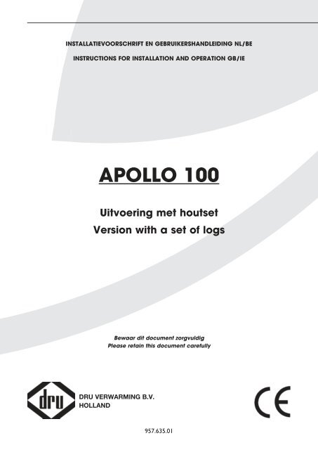
INSTALLATIEVOORSCHRIFT EN GEBRUIKERSHANDLEIDING NL/BEINSTRUCTIONS FOR INSTALLATION AND OPERATION GB/IEAPOLLO 100Uitvoering met houtsetVersion with a set of logsBewaar dit docum<strong>en</strong>t zorgvuldigPlease retain this docum<strong>en</strong>t carefullyDRU VERWARMING B.V.HOLLAND957.635.01
1190150100100615494154min 1055max 1105min 190max 24055038c-1357<strong>Apollo</strong> 100
Belangrijk• Het toestel moet word<strong>en</strong> uitgerust met e<strong>en</strong> bedi<strong>en</strong>ingsluik (meegeleverd),lees de instructies hier voor!• De boezem di<strong>en</strong>t ontlucht te word<strong>en</strong>, evt met de beschikbare DRU ontluchters (2x) of andersdoor op<strong>en</strong>ing<strong>en</strong> of roosters met e<strong>en</strong> minimale gezamelijke doorlaat van 200 cm 2 .• Zorg er voor dat de rand<strong>en</strong> bij strakke inbouw mooi afgewerkt word<strong>en</strong> want deze kom<strong>en</strong> in het zicht, zorg er tev<strong>en</strong>svoor dat m<strong>en</strong> niet op of over de rand<strong>en</strong> stuckt.• Let erop dat u bij het in- <strong>en</strong> uitnem<strong>en</strong> van het glasraam de boezem of de schouw niet beschadigd.• Het is niet toegestaan het toestel te voorzi<strong>en</strong> van e<strong>en</strong> isolatie dek<strong>en</strong> of op <strong>en</strong>ige wijze in te pakk<strong>en</strong> of af te dekk<strong>en</strong>.• Voordat m<strong>en</strong> het toestel in gebruik neemt di<strong>en</strong>t u altijd de ruit schoon te mak<strong>en</strong>, dit om inbrand<strong>en</strong> van evt.verontreiniging<strong>en</strong>, zoals vingerafdrukk<strong>en</strong> teg<strong>en</strong> te gaan.• Dit toestel mag uitsluit<strong>en</strong>d met het door DRU geleverde afvoermateriaal Ø150/Ø100 geïnstalleerd word<strong>en</strong>.• De ruimte tuss<strong>en</strong> de pot<strong>en</strong> di<strong>en</strong>t vrij te blijv<strong>en</strong>.• Het toestel mag niet strak teg<strong>en</strong> de achterwand word<strong>en</strong> gemonteerd.• De ontstekingskabel mag niet over de ontvanger ligg<strong>en</strong> <strong>en</strong> de ant<strong>en</strong>ne rak<strong>en</strong> of kruis<strong>en</strong>.• De ontstekingskabel mag niet langs metal<strong>en</strong> del<strong>en</strong> gelegd word<strong>en</strong>. Dit verzwakt de vonk.• Let op dat er NOOIT vermiculiet, chips, stamm<strong>en</strong> of grind op of tuss<strong>en</strong> de waakvlam ligt.Dit kan de ontsteking <strong>en</strong> de werking van de waakvlam ernstig verstor<strong>en</strong>!• De waakvlambrander <strong>en</strong> de ruimte er omhe<strong>en</strong> moet<strong>en</strong> t<strong>en</strong> all<strong>en</strong> tijde word<strong>en</strong> vrijgelat<strong>en</strong> zodat de vlam niet wordtgeblokkeerd.• De positionering van de takjes of carrara ste<strong>en</strong>tjes is ge<strong>en</strong> vrijblijv<strong>en</strong>d advies maar moet exact conform de beschrijvingword<strong>en</strong> uitgevoerd. Indi<strong>en</strong> dit niet gebeurt zou dit tot gevaarlijke situaties kunn<strong>en</strong> leid<strong>en</strong>.Important• The appliance should be fitted with a service flap (provided), please read the instructions!• The chimney breast should be v<strong>en</strong>tilated, e.g. with the DRU v<strong>en</strong>ts available (2x) or alternatively with op<strong>en</strong>ings or grilleswith a minimum total free v<strong>en</strong>t area of 200 cm 2 .• If the fire is to be built in, flush with the wall, make sure the edges are neatly finished and not plastered over as they willremain visible.• Be careful not to damage the chimney breast or fireplace wh<strong>en</strong> placing or removing the glass pane.• The appliance must not be fitted with an insulation blanket or in any other way wrapped or covered.• Always clean the glass pane before using the fire to avoid marks such as fingerprints burning in.• This appliance may only be installed using the Ø150/Ø100 flue material supplied by DRU.• The space betwe<strong>en</strong> the feet must remain op<strong>en</strong>.• The appliance must not be mounted too closely against the back wall.• The ignition wire must not lie across the receiver or touch or cross the aerial.• The ignition wire must not be laid along metal elem<strong>en</strong>ts as this will weak<strong>en</strong> the spark.• NB: There must NEVER be any vermiculite, chips, logs or gravel on or in the pilot light. This could seriously interfere withits ignition and functioning!• The pilot burner and the space around it must always be kept clear of obstruction so that the flame remains unblockedat all times.• It is vitally important that you adhere to the correct positioning of the twigs or pebbles as specified. Failure to do thismay result in an unsafe situation.<strong>Apollo</strong> 100
Hierbij verklar<strong>en</strong> wij dat de DRU modell<strong>en</strong> <strong>Apollo</strong> in overe<strong>en</strong>stemming zijn met het CE typeonderzoekscertificaatE 1490 <strong>en</strong> dat zij voldo<strong>en</strong> aan de Europese richtlijn inzake gastoestell<strong>en</strong> 90/396/EEC.We here by declare that the DRU models <strong>Apollo</strong> are in conformity with the types as described in EC typecertificateE 1490 and that they are in compliance with the European Council gas appliance directive 90/396/EEC.
INHOUDINHOUDWoord vooraf .......................................................................2Uitpakk<strong>en</strong> ...............................................................................2Aansluit<strong>en</strong> ...............................................................................2Installatievoorschrift ............................................................2Gassoort .................................................................................2Belangrijk ................................................................................2Plaats<strong>en</strong> van het toestel ......................................................2Bedi<strong>en</strong>ingsluikje .....................................................................4Aansluitmogelijkhed<strong>en</strong> ........................................................4Voorbereiding<strong>en</strong> voor het plaats<strong>en</strong> vanhet in- <strong>en</strong> uitlaatsysteem ....................................................5Geveldoorvoer met conc<strong>en</strong>trische pijp<strong>en</strong> ....................5Dakdoorvoer met conc<strong>en</strong>trische pijp<strong>en</strong> ........................5Bestaande schoorste<strong>en</strong> .......................................................6Instelling<strong>en</strong> restrictieschuif .................................................6Restrictieschuif instell<strong>en</strong> .....................................................6Aansluiting van de gastoevoer...........................................6Glasraam .................................................................................8Verwijder<strong>en</strong> glasraam ..........................................................8Plaats<strong>en</strong> glasraam ..................................................................8Plaats<strong>en</strong> luchtgeleidingsonderdel<strong>en</strong> ..................................9Plaats<strong>en</strong> van de houtset ....................................................12Gebruikershandleiding ......................................................18Draadloze afstandsbedi<strong>en</strong>ing ...........................................18Ontvanger ............................................................................18Vervang<strong>en</strong> batterij<strong>en</strong> .........................................................18Afstandsbedi<strong>en</strong>ing ...............................................................19Instell<strong>en</strong> communicatiecode ............................................19MAN stand...........................................................................19Ontstek<strong>en</strong> ............................................................................20Vlamhoogte / standby ........................................................20Uitschakel<strong>en</strong> ........................................................................20Temperatuurweergave ......................................................20Tijd .........................................................................................20Thermostaat functie ..........................................................20Instell<strong>en</strong> dag-/nachttemperatuur .....................................21Activer<strong>en</strong> thermostaat functie ........................................21Timer voor thermostaat functie .....................................21Instell<strong>en</strong> tijd<strong>en</strong> t.b.v. timer ...............................................21Activer<strong>en</strong> timer functie .....................................................21Vervang<strong>en</strong> batterij ..............................................................21Algem<strong>en</strong>e opmerking<strong>en</strong> ....................................................22Onderhoud <strong>en</strong> reiniging ...................................................22Verkleuring van wand<strong>en</strong> <strong>en</strong> plafonds .............................22Eerste maal stok<strong>en</strong>.............................................................22Extra bescherming .............................................................22Afdank<strong>en</strong> ...............................................................................22Garantie ................................................................................22Fout<strong>en</strong>zoekschema.............................................................23Technische gegev<strong>en</strong>s .........................................................49Nederlands1<strong>Apollo</strong> 100
INSTALLATIEVOORSCHRIFTWoord voorafGeachte klant,Vri<strong>en</strong>delijk bedankt voor de aankoop van dit DRUproduct. Onze product<strong>en</strong> zijn ontwikkeld <strong>en</strong> gefabriceerdvolg<strong>en</strong>s de hoogst mogelijke kwaliteits-, prestatie- <strong>en</strong>veiligheidseis<strong>en</strong>. Hierdoor kunt u rek<strong>en</strong><strong>en</strong> op jar<strong>en</strong>langprobleemloos gebruiksplezier.Het toestel is voorzi<strong>en</strong> van e<strong>en</strong> geslot<strong>en</strong>verbrandingsruimte. De verbrandingslucht wordt met e<strong>en</strong>gecombineerde in-, <strong>en</strong> uitlaat van buit<strong>en</strong> aangezog<strong>en</strong> doorde natuurlijke trek van de verbrandingsgass<strong>en</strong>.Voor de veilige werking zijn de toestell<strong>en</strong> voorzi<strong>en</strong> vane<strong>en</strong> tweede thermokoppel dat op de hoofdbrander isgeplaatst.In dit boekje vindt u instructies voor installatie <strong>en</strong>gebruik van uw nieuwe toestel. Lees de instructies <strong>en</strong>gebruikershandleiding goed door, zodat u zich vertrouwdmaakt met het toestel. Wilt u meer ondersteuning, neemdan contact op met uw leverancier.Uitpakk<strong>en</strong>Wanneer u klaar b<strong>en</strong>t met uitpakk<strong>en</strong>, di<strong>en</strong>t de verpakkingvia de reguliere weg te word<strong>en</strong> afgevoerd.Aansluit<strong>en</strong>Dit toestel di<strong>en</strong>t te word<strong>en</strong> aangeslot<strong>en</strong> door e<strong>en</strong> bevoegdgasinstallateur.Belangrijk• De boezem di<strong>en</strong>t “ontlucht” te word<strong>en</strong>.• Het is niet toegestaan het toestel op <strong>en</strong>ige wijze in tepakk<strong>en</strong> of af te dekk<strong>en</strong>.• Voordat m<strong>en</strong> het toestel in gebruik neemt di<strong>en</strong>t u altijdde ruit schoon te mak<strong>en</strong>, dit om inbrand<strong>en</strong> van evt.verontreiniging<strong>en</strong>, zoals vingerafdrukk<strong>en</strong> teg<strong>en</strong> te gaan.• Dit toestel mag uitsluit<strong>en</strong>d met het door DRU geleverdeafvoermateriaal Ø150/Ø100 geïnstalleerd word<strong>en</strong>.• Let op: Om e<strong>en</strong> goede ontsteking te waarborg<strong>en</strong> moet deontstekingskabel zoveel mogelijk vrij ligg<strong>en</strong> van de metal<strong>en</strong>del<strong>en</strong> van het toestel. Draai deze dus niet om degas- waakvlam-, of thermokoppelleiding.• Laat thermokoppel 2 <strong>en</strong> de ruimte er omhe<strong>en</strong> vrij;”• Zorg ervoor dat de drad<strong>en</strong> van thermokoppel 2 vrij ligg<strong>en</strong>van del<strong>en</strong> die warm word<strong>en</strong>.INSTALLATIEVOORSCHRIFTGassoortDit toestel is bestemd voor het land <strong>en</strong> geschikt voorde gassoort dat is vermeld op de typeplaat. Controleerof de gassoort <strong>en</strong> de gasdruk ter plaatse overe<strong>en</strong>kom<strong>en</strong>met de vermelding op het typeplaatje aan de ketting. Dittypeplaatje bevind zich op de metal<strong>en</strong> plaat welke aan deketting zit.Houdt u aan de gasinstallatievoorschrift<strong>en</strong> <strong>en</strong> ev<strong>en</strong>tueleplaatselijke voorschrift<strong>en</strong>. Het toestel di<strong>en</strong>t door e<strong>en</strong>bevoegd gasinstallateur te word<strong>en</strong> aangeslot<strong>en</strong>.Belangrijk• Zorg ervoor dat evt. overgordijn<strong>en</strong> of andere brandbarematerial<strong>en</strong> minst<strong>en</strong>s 50 cm van het toestel verwijderd zijn.• Let op! Aanraking van hete del<strong>en</strong> kan brandwond<strong>en</strong>veroorzak<strong>en</strong>!• Het toestel di<strong>en</strong>t door e<strong>en</strong> erk<strong>en</strong>d gasinstallateurgeïnstalleerd te word<strong>en</strong>.• Natte kleding, handdoek<strong>en</strong> e.d. niet op de kachel tedrog<strong>en</strong> hang<strong>en</strong>!Plaats<strong>en</strong> van het toestelHet toestel is ontworp<strong>en</strong> om strak in te bouw<strong>en</strong> in e<strong>en</strong>nieuw te bouw<strong>en</strong> boezem van onbrandbaar <strong>en</strong>hittebest<strong>en</strong>dig materiaal.M<strong>en</strong> moet bij dit toestel gebruik mak<strong>en</strong> van e<strong>en</strong>bedi<strong>en</strong>ingsluikje (mee geleverd).Het bedi<strong>en</strong>ingsluikje moet binn<strong>en</strong> e<strong>en</strong> afstand van 1 mtrlinks of rechts van de kachel geplaatst word<strong>en</strong> i.v.m. del<strong>en</strong>gte van de leiding<strong>en</strong>.Voor afmeting<strong>en</strong> <strong>en</strong> montagevoorschrift<strong>en</strong> zie hoofdstukbedi<strong>en</strong>ingsluikje.Indi<strong>en</strong> u de boezem bouwt van e<strong>en</strong> materiaal anders danste<strong>en</strong> (b.v. promatect), rad<strong>en</strong> wij u aan glasvezel behang tegebruik<strong>en</strong> <strong>en</strong> ge<strong>en</strong> stucwerk. Voor het geval u tochstucwerk toepast moet u er op lett<strong>en</strong> dat er niet overde fl<strong>en</strong>s<strong>en</strong> gestuct wordt. Er kunn<strong>en</strong> hierdoor scheur<strong>en</strong>ontstaan door de warmte van het toestel.Let op dat er voldo<strong>en</strong>de ruimte is voor de diepte van hetToestel (500 mm).Het toestel mag niet strak teg<strong>en</strong> de achterwand word<strong>en</strong>gemonteerd.De inbouwhoogte is afhankelijk van de instelling van destelvoet<strong>en</strong>.Plaats vervolg<strong>en</strong>s het toestel op de gew<strong>en</strong>ste plaats.Houd in de boezem voldo<strong>en</strong>de ruimte rondom het toestelzodat de warmte weg kan. Voor e<strong>en</strong> goede warmte afvoer,di<strong>en</strong>t de boezem bov<strong>en</strong> voldo<strong>en</strong>de ontlucht te word<strong>en</strong>.De gezam<strong>en</strong>lijke doorlaat moet minimaal 200 cm 2 zijn.Wij rad<strong>en</strong> u aan de ontluchting aan weerszijde uit te voer<strong>en</strong>.DRU heeft hiervoor design ontluchters in haar programma.Haal de tas met toebehor<strong>en</strong> uit de verbrandingskamer doorhet glasraam te verwijder<strong>en</strong>. (zie hoofdstuk Verwijder<strong>en</strong>glasraam).2
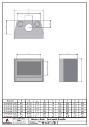
INSTALLATIEVOORSCHRIFTMaximale stuc lijnHaardMaximale stuc lijnNederlandsmin 1400mmmin 500mmTotale ontluchting 200 cm 2x 554mmmax 100mmy1070mm1010 mm38c-1141yfig. 13<strong>Apollo</strong> 100
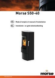
INSTALLATIEVOORSCHRIFTHet monter<strong>en</strong> gaat in omgekeerde volgorde. Het toestelis voorzi<strong>en</strong> van beugels voor wandmontage (fig. 2). Dezedi<strong>en</strong><strong>en</strong> ook gebruikt te word<strong>en</strong>. Sluit het toestel aan.Het toestel mag niet strak teg<strong>en</strong> de achterwand word<strong>en</strong>gemonteerd.Ga hierbij als volgt te werk.Maak de flexibele gasleiding (sleutel 17), aluminiumwaakvlamleiding (sleutel 10) <strong>en</strong> thermokoppel 1 (sleutel10) los <strong>en</strong> wikkel de leiding<strong>en</strong> af, zorg dat er ge<strong>en</strong> knikk<strong>en</strong>ontstaan.Wandbeugelsfig. 238c-1142Bedi<strong>en</strong>ingsluikje (fig. 3a)Voor het bedi<strong>en</strong>ingsluikje moet u e<strong>en</strong> gat mak<strong>en</strong> van285 mm x 194 mm (h x b).Plaats het binn<strong>en</strong>frame (1). Deze kunt u mee metsel<strong>en</strong>4512fig. 3b!Let op De rode draad van thermokoppel 2 blijftaangeslot<strong>en</strong> op het gasregelblok. In Fig. 3b is aangegev<strong>en</strong>hoe de drad<strong>en</strong> op het thermokoppel zijn bevestigd.Verwijder vervolg<strong>en</strong>s het gasregelblok.Leid de leiding<strong>en</strong> naar de gew<strong>en</strong>ste positie, let op dat erge<strong>en</strong> vuil in de leiding<strong>en</strong> komt.Rol voorzichtig de rode <strong>en</strong> zwarte draad vanthermokoppel 2 uit;Leg het gasregelblok sam<strong>en</strong> met de drad<strong>en</strong> vanthermokoppel 2 in de richting van het bedi<strong>en</strong>ingskastje.Monteer het gasregelblok aan de beugels (2) van hetbinn<strong>en</strong> frame.Sluit de leiding<strong>en</strong> aan op de achterzijde van hetgasregelblok.Let er op dat u de flexibele slang <strong>en</strong> de aluminium leidinggasdicht aandraait.Thermokoppel 1 moet m<strong>en</strong> eerst handvast aandraai<strong>en</strong> <strong>en</strong>vervolg<strong>en</strong>s 1 kwart slag met de sleutel.Plaats de ontvanger van de afstandsbedi<strong>en</strong>ing in het bakje (3).Maak het buit<strong>en</strong>frame met deurtje (4) vast aan hetbinn<strong>en</strong>frame met behulp van de twee parkers (5).U kunt het buit<strong>en</strong>frame zo plaats<strong>en</strong> afhankelijk of u hetdeurtje links of rechts draai<strong>en</strong>d wilt hebb<strong>en</strong>.3fig. 3a38c-1078indi<strong>en</strong> u e<strong>en</strong> boezem van ste<strong>en</strong> gebruikt. Indi<strong>en</strong> u e<strong>en</strong>ander materiaal gebruikt kunt u het binn<strong>en</strong>frame vastkitt<strong>en</strong>of met vier verzonk<strong>en</strong> schroefjes vastzett<strong>en</strong>.Af fabriek is het gasregel blok onder het toestelgemonteerd.In de praktijk mag het gasregelblok niet onder het toestelblijv<strong>en</strong> zitt<strong>en</strong> <strong>en</strong> di<strong>en</strong>t los g<strong>en</strong>om<strong>en</strong> te word<strong>en</strong>.Aansluitmogelijkhed<strong>en</strong> (fig. 4)De doorvoer naar buit<strong>en</strong> kan zowel door de gevel alsdoor het dakvlak plaatsvind<strong>en</strong>, het aansluit<strong>en</strong> van de aan<strong>en</strong>afvoerpijp<strong>en</strong> di<strong>en</strong>t aan onderstaande voorwaard<strong>en</strong> tevoldo<strong>en</strong>:• altijd eerst 1 of 1,2 meter pijp verticaal plaats<strong>en</strong>.• Bij 1 meter verticaal mag de horizontale pijpl<strong>en</strong>gte magnooit langer zijn dan 1 meter <strong>en</strong> e<strong>en</strong> muurdoorvoer.• Bij 1,2 meter verticaal mag de horizontale pijpl<strong>en</strong>gte magnooit langer zijn dan 2 meter <strong>en</strong> e<strong>en</strong> muurdoorvoer.• de maximale pijpl<strong>en</strong>gte is 12 meter.Rek<strong>en</strong> voor e<strong>en</strong> 90° bocht 2 meter <strong>en</strong> voor e<strong>en</strong> 45° bocht1 meter. De l<strong>en</strong>gte van de gevel- of dakdoorvoer hoeftniet te word<strong>en</strong> meegerek<strong>en</strong>d.4
2mINSTALLATIEVOORSCHRIFTDe maximale totale l<strong>en</strong>gte is de som van de buisl<strong>en</strong>gteplus de vervang<strong>en</strong>de l<strong>en</strong>gte voor de bocht<strong>en</strong> (zie de5 voorbeeld<strong>en</strong> in fig. 4).De dakdoorvoerset, luchtaanvoer / rookgasafvoer, deconc<strong>en</strong>trische pijp <strong>en</strong> bocht<strong>en</strong> word<strong>en</strong> per stuk verpakt<strong>en</strong> compleet geleverd met e<strong>en</strong> klemband voorzi<strong>en</strong> vanafdichtring. Tev<strong>en</strong>s is e<strong>en</strong> pan- of plakplaat verkrijgbaarvoor doorvoer door resp. e<strong>en</strong> schuin of e<strong>en</strong> plat dak.Let op: Dit toestel mag uitsluit<strong>en</strong>d met het door DRUgeleverde afvoermateriaal Ø150/Ø100 geïnstalleerdword<strong>en</strong>. Dit is sam<strong>en</strong> met het toestel gekeurd <strong>en</strong> voldoethiermee aan alle eis<strong>en</strong>. Voor afwijk<strong>en</strong>d installatiemateriaalkan DRU de goede <strong>en</strong> veilige werking niet garander<strong>en</strong>.Voorbereiding<strong>en</strong> voor het plaats<strong>en</strong> van hetin- <strong>en</strong> uitlaatsysteem• Maak e<strong>en</strong> keuze uit de aansluitmogelijkhed<strong>en</strong> volg<strong>en</strong>sfiguur 4.• Bouw de conc<strong>en</strong>trische pijp<strong>en</strong> op vanaf het toestel. Alsdoor bouwkundige omstandighed<strong>en</strong> eerst e<strong>en</strong> gedeeltevan het conc<strong>en</strong>trische pijp<strong>en</strong>systeem wordt ingebouwdlet dan speciaal op de juiste montagewijze.• Het toestel begint met e<strong>en</strong> contradeel. Hierop de eerstemeter pijp plaats<strong>en</strong>.• Houdt e<strong>en</strong> minimale afstand aan van 5 c<strong>en</strong>timeter tuss<strong>en</strong>de buit<strong>en</strong>kant van de conc<strong>en</strong>trische pijp<strong>en</strong> <strong>en</strong> wand ofplafond.Geveldoorvoer met conc<strong>en</strong>trische pijp<strong>en</strong>Let op dat bij de geveldoorvoer eerst 1 of 1,2 meter pijpverticaal gemonteerd moet word<strong>en</strong>. 1 meter bij maximaal1 meter horizontaal <strong>en</strong> 1,2 meter bij maximaal 2 meterhorizontaal.• Bepaal de plaats van het toestel <strong>en</strong> van de plaats van degeveldoorvoer.• Maak op de plaats van de geveldoorvoer e<strong>en</strong> gat vanØ160 mm, door brandbaar materiaal Ø 230 mm.• Sluit nu één of meerdere conc<strong>en</strong>trische pijp<strong>en</strong> verticaalaan op de uitmonding van het toestel. <strong>Dru</strong>k deze aan <strong>en</strong>br<strong>en</strong>g de klemband(<strong>en</strong>) aan.• Plaats hierop de bocht <strong>en</strong> ev<strong>en</strong>tuele horizontaleconc<strong>en</strong>trische pijp<strong>en</strong> <strong>en</strong> maak deze rook gasdicht.• Sluit de geveldoorvoer aan op de bocht of horizontalepijpl<strong>en</strong>gte <strong>en</strong> zorg dat deze ook gasdicht wordt afgeslot<strong>en</strong>.• Plaats de horizontale conc<strong>en</strong>trische pijpstukk<strong>en</strong> onderafschot naar de geveldoorvoer ter voorkoming vaninwater<strong>en</strong>d reg<strong>en</strong>water.Dakdoorvoer met conc<strong>en</strong>trische pijp<strong>en</strong>E<strong>en</strong> dakdoorvoer kan op elk punt van het dak uitmond<strong>en</strong>,ev<strong>en</strong>tueel met e<strong>en</strong> versleping naar de nok. De dakdoorvoerwordt afhankelijk van één van bov<strong>en</strong>staande mogelijkhed<strong>en</strong>geleverd met e<strong>en</strong> plakplaat voor e<strong>en</strong> plat dak of e<strong>en</strong>universeel verstelbare pan voor e<strong>en</strong> schuin dak.• Bepaal de plaats van het toestel <strong>en</strong> van de plaats van dedakdoorvoer.• Maak op de plaats van de dakdoorvoer e<strong>en</strong> gat vanØ160 mm, door brandbaar materiaal Ø 230 mm.Nederlands5m12x45˚4m22x90˚1m1mL=1+2+5+(2x1)=10L=1+1+4+(2x2)=10(H totaal= 5m)1m33445512121m1m1x90˚1x90˚1,2m 1,2m1x90˚1x90˚L=2+0,5+(2)=4,5L=2+0,5+(2)=4,5fig. 4max 1mmax 1mL=4+1+(2)=7L=4+1+(2)=7max 2mmax 2m38c-744b38c-744b5<strong>Apollo</strong> 100
INSTALLATIEVOORSCHRIFT• Sluit nu de conc<strong>en</strong>trische pijp<strong>en</strong> verticaal aan op deuitmonding van het toestel. <strong>Dru</strong>k deze aan <strong>en</strong> br<strong>en</strong>g deklemband aan.• Bepaal de l<strong>en</strong>gte van de b<strong>en</strong>odigde pijp<strong>en</strong> <strong>en</strong> zorg ervoordat de plakplaat of de universele pan goed aansluit op hetdak.• Zaag de buit<strong>en</strong>pijp af op de juiste l<strong>en</strong>gte.• Sluit de dakdoorvoer aan op de conc<strong>en</strong>trische pijp<strong>en</strong>.Let op: u kunt ook eerst de conc<strong>en</strong>trische pijp<strong>en</strong>aanbr<strong>en</strong>g<strong>en</strong> alvor<strong>en</strong>s het toestel te plaats<strong>en</strong>.U di<strong>en</strong>t dan de aansluiting op de uitmonding vanhet toestel te mak<strong>en</strong> met e<strong>en</strong> inkortbare pijp.Bestaande schoorste<strong>en</strong>Het is ook mogelijk om het toestel op e<strong>en</strong> bestaandeschoorste<strong>en</strong> aan te sluit<strong>en</strong>. Hiervoor wordt door DRUe<strong>en</strong> speciale schoorste<strong>en</strong> aansluitset geleverd. Daarin vindtu ook e<strong>en</strong> installatievoorschrift voor deze aansluitset.Bij aansluiting op e<strong>en</strong> bestaande schoorste<strong>en</strong> moet<strong>en</strong>geld<strong>en</strong> de volg<strong>en</strong>de punt<strong>en</strong>:• De schoorste<strong>en</strong> moet minimaal Ø150 mm zijn.• De totale l<strong>en</strong>gte mag niet meer zijn dan 12 m verticaalof niet meer dan 2 m horizontaal.• De schoorste<strong>en</strong> di<strong>en</strong>t voor de installatie goed gereinigd teword<strong>en</strong>.Instelling<strong>en</strong> restrictieschuifOm e<strong>en</strong> goede werking van het toestel te waarborg<strong>en</strong>di<strong>en</strong>t m<strong>en</strong> de restrictieschuif zo in te stell<strong>en</strong>, zodat hettoestel optimaal wordt afgesteld op het klantspecifiekepijp<strong>en</strong>systeem.Restrictieschuif instell<strong>en</strong>De restrictieschuif wordt los meegeleverd <strong>en</strong> moet in hettoestel word<strong>en</strong> geplaatst zoals aangegev<strong>en</strong> in fig. 6.Met behulp van de bijgeleverde afstelmal (fig. 5) kan deG25/G20schuif op de juiste maat afgesteld word<strong>en</strong>. Na het afstell<strong>en</strong>kan de restrictieschuif vastgezet word<strong>en</strong> met de inbusbout.Het afstell<strong>en</strong> moet gebeur<strong>en</strong> volg<strong>en</strong>s de gegev<strong>en</strong>s in detabel. Monteer vervolg<strong>en</strong>s het middelste deel van derookgas geleiding.Let op dat de maximale horizontale l<strong>en</strong>gte nietwordt overschred<strong>en</strong>.In figuur 4 is geïllustreerd hoe de totale l<strong>en</strong>gt<strong>en</strong> moet<strong>en</strong>word<strong>en</strong> berek<strong>en</strong>d.Aansluiting van de gastoevoerGebruik in de toevoerleiding e<strong>en</strong> gekeurde aansluitkraanmet koppeling (voor België moet deze B.G.V. gekeurdzijn). Verder geldt:• Ontlucht de toevoerleiding voordat het toestel wordtvastgekoppeld.• De bedi<strong>en</strong>ingskraan mag niet verdraaid word<strong>en</strong> bij hetaansluit<strong>en</strong> aan de gastoevoerleiding.• Vermijd spanning<strong>en</strong> op de bedi<strong>en</strong>ingskraan <strong>en</strong> leiding<strong>en</strong>.• Controleer de aansluiting<strong>en</strong> op gasdichtheid.38c-1158fig. 6RestrictieschuifRestrictie- Afstand Luchtinlaatschuifrestrictie- Geleidersschuif (hoeklijn<strong>en</strong>)fig. 51 mtr verticaal + dakdoorvoer JA 53 mm JA2 t/m 3 mtr verticaal + dakdoorvoer JA 48 mm JA4 t/m 5 mtr verticaal + dakdoorvoer JA 43 mm JA6 t/m 7 mtr verticaal + dakdoorvoer JA 38 mm JA8 t/m 9 mtr verticaal + dakdoorvoer JA 35 mm JA10 t/m 12 mtr verticaal +dakdoorvoer JA 33 mm JA1 mtr verticaal + 90˚ bocht + muurdoorvoer GEEN OPEN JA1 mtr verticaal + 90˚ bocht+ max 1 mtr horizontaal + muurdoorvoerGEEN OPEN JA1,2 mtr verticaal + 90˚ bocht+ max 2 mtr horizontaal + muurdoorvoerGEEN OPEN GEEN6
INSTALLATIEVOORSCHRIFTNederlands8 9101112a12b12c137<strong>Apollo</strong> 100
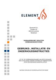
INSTALLATIEVOORSCHRIFT14 151617GlasraamNa het plaats<strong>en</strong> van de houtset kan het glasraam geplaatstword<strong>en</strong> zoals hieronder is beschrev<strong>en</strong>.Verwijder<strong>en</strong> glasraamVoor het verwijder<strong>en</strong> van het glasraam volgt uonderstaande aanwijzing<strong>en</strong> (zie Fig. 8 t/m 17):• Verwijder de verticale sierstrip aan de linker- <strong>en</strong> derechterkant door het lipje bov<strong>en</strong>aan de strip omhoog tedrukk<strong>en</strong>, de strip ev<strong>en</strong>wijdig aan het glasraam te kantel<strong>en</strong><strong>en</strong> deze vervolg<strong>en</strong>s uit te nem<strong>en</strong>.• Verwijder de horizontale sierstrip door deze met 2hand<strong>en</strong> in de sleuf vast te pakk<strong>en</strong> <strong>en</strong> uit te licht<strong>en</strong>.• Draai de 4 parkers uit de onderste strip van het glasraammet behulp van de bijgeleverde dopsleutel.• Draai de 3 parkers van de fixeerstrip aan beide zijkant<strong>en</strong> 2slag<strong>en</strong> los.• Let op: Draai de parkers niet uit, maar laat deze in defixeerstrip zitt<strong>en</strong>.• <strong>Dru</strong>k de 2 bov<strong>en</strong>ste wigg<strong>en</strong> (links <strong>en</strong> rechts) zovermogelijk omlaag.• <strong>Dru</strong>k de 2 onderste wigg<strong>en</strong> zover mogelijk omhoog.• <strong>Dru</strong>k met uw hand beide fixeerstripp<strong>en</strong> zover mogelijknaar buit<strong>en</strong> om te voorkom<strong>en</strong> dat het afdichtingskoordwordt beschadigd.• Pak de handgreep onder <strong>en</strong> bov<strong>en</strong> vast <strong>en</strong> til het raamomhoog.• Kantel het glasraam m.b.v. de onderste handgreep naaru toe door de op<strong>en</strong>ing in het montageframe <strong>en</strong> trekgelijktijdig het glasraam aan de bov<strong>en</strong>zijde maximaal naaru toe.• Let op: Zorg ervoor dat u de bov<strong>en</strong>ste handgreep stevigvasthoudt. Als deze losschiet, kan het glasraam naarbinn<strong>en</strong> vall<strong>en</strong> <strong>en</strong> kan zowel het glasraam als het toestelernstige schade oplop<strong>en</strong>.• Zorg ervoor dat u het glasraam zoveel mogelijk in hetmidd<strong>en</strong> van het montageframe naar buit<strong>en</strong> beweegt ombeschadiging van lakdel<strong>en</strong> <strong>en</strong> het afdichtingskoord tevoorkom<strong>en</strong>.• Laat het glasraam schuin naar onder<strong>en</strong> zakk<strong>en</strong> totdat ditvolledig uit het montage frame g<strong>en</strong>om<strong>en</strong> kan word<strong>en</strong>.Plaats<strong>en</strong> glasraamHet plaats<strong>en</strong> van het glasraam gaat in omgekeerdevolgorde van het verwijder<strong>en</strong> zoals hierbov<strong>en</strong> isbeschrev<strong>en</strong>.Let op: Vermijd/verwijder vingerafdrukk<strong>en</strong> op de ruitomdat deze inbrand<strong>en</strong>.- Draai de parkers niet te vast ter voorkoming vanafbrek<strong>en</strong> <strong>en</strong> / of doldraai<strong>en</strong>: vast=vast.- Vervang de fixeerstrip als het afdichtingskoord heeftlosgelat<strong>en</strong>.Neem de volg<strong>en</strong>de aanwijzing<strong>en</strong> in acht bij hetterugplaats<strong>en</strong>:• Controleer eerst of de beide fixeerstripp<strong>en</strong> zovermogelijk naar buit<strong>en</strong> zijn gedrukt om te voorkom<strong>en</strong> dathet afdichtingskoord wordt beschadigd.• Plaats het glasraam terug.• Controleer of de haak aan de bov<strong>en</strong>kant van het glasraamin de zitting / U-vormige strip ligt.8
INSTALLATIEVOORSCHRIFT• Tip: Probeer het glasraam met de bov<strong>en</strong>ste handgreepnaar u toe te trekk<strong>en</strong>: als dit niet lukt, is het glasraamgoed teruggeplaatst.• Let op: Zet de onderste strip van het glasraam weer vastmet de 4 parkers.• Duw de beide onderste wigg<strong>en</strong> omlaag.• Duw de bov<strong>en</strong>ste wigg<strong>en</strong> omhoog zodat beidefixeerstripp<strong>en</strong> met het afdichtingskoord teg<strong>en</strong> de ruitdrukk<strong>en</strong>.• Draai vervolg<strong>en</strong>s de parker bij elke wig vast.• Let op: <strong>Dru</strong>k tijd<strong>en</strong>s het vastdraai<strong>en</strong> de wig aan met uwhand.• Draai vervolg<strong>en</strong>s de middelste parker van beidefixeerstripp<strong>en</strong> vast.• Plaats de horizontale sierstrip.• Plaats de verticale sierstripp<strong>en</strong>.Plaats<strong>en</strong> luchtgeleidingsonderdel<strong>en</strong>• Controleer of de plat<strong>en</strong> A nog op de plaats ligg<strong>en</strong> zoalsaangegev<strong>en</strong> in fig. 18A. Let op dat de uitkeping<strong>en</strong> van deplat<strong>en</strong> over de parkers van de pootjes van de voorstebrander zijn geschov<strong>en</strong>, zie omcirkelde in fig. 18A.Dit is belangrijk, anders past het geheel straks niet!• Indi<strong>en</strong> nodig, zie tabel pagina 6: plaats vervolg<strong>en</strong>s deluchtinlaatgeleiders (hoeklijn<strong>en</strong>), zoals aangegev<strong>en</strong> in fig.18B <strong>en</strong> 18C met de p<strong>en</strong>netjes in de sleufjes van plat<strong>en</strong> A,zie het omcirkelde in fig. 18B.• Plaats vervolg<strong>en</strong>s de luchtgeleidingsschott<strong>en</strong> B <strong>en</strong> C volg<strong>en</strong>sfig. 18B, 18C <strong>en</strong> 18D. Hier ook met de p<strong>en</strong>netjes in desleufjes, zie het omcirkelde in fig. 18B <strong>en</strong> 18D. Let opdat de schott<strong>en</strong> volg<strong>en</strong>s fig. 18D kom<strong>en</strong> te ligg<strong>en</strong>, zodatde schott<strong>en</strong> bij de pijlpunt<strong>en</strong> in fig. 18B aansluit<strong>en</strong> op debranders.• Plaats vervolg<strong>en</strong>s het rooster E zoals in fig. 18D <strong>en</strong> E.NederlandsAAfig. 18A9<strong>Apollo</strong> 100
INSTALLATIEVOORSCHRIFTfig. 18Bfig. 18C10
INSTALLATIEVOORSCHRIFTACANederlandsBEfig. 18DEfig. 18E11<strong>Apollo</strong> 100
INSTALLATIEVOORSCHRIFTPlaats<strong>en</strong> van de houtset• Plaats de plat<strong>en</strong> F(806429) <strong>en</strong> G(806430) met de gladdekant naar bov<strong>en</strong>, zoals in figuur 19A, 19B <strong>en</strong> detail 19C.Laat de plat<strong>en</strong> aansluit<strong>en</strong> bij de pijlpunt<strong>en</strong>. Er ontstaatrondom de brander e<strong>en</strong> kier, dit is normaal.Pas op! De plat<strong>en</strong> zijn breekbaar.• Vul de branderbakk<strong>en</strong> met zwarte vermiculiet H <strong>en</strong>verdeel het gelijkmatig, zie fig. 20.(Het vermiculiet zit in e<strong>en</strong> plastic zakje bij de houtset).• Plaats stam 1 <strong>en</strong> 2 zoals aangegev<strong>en</strong> in fig. 21B. Let op datstam 1 teg<strong>en</strong> de nokk<strong>en</strong> (y) wordt aangelegd, zodat deafstand x links <strong>en</strong> rechts ongeveer gelijk is.Stam 2 positioner<strong>en</strong> op de blokk<strong>en</strong>steun (z), welke zichaan het luchtgeleidingsschot C bevindt.• Plaats stam 3 zoals aangegev<strong>en</strong> in fig. 21E.Het nokje van stam 3 komt in het gat van stam 2 te ligg<strong>en</strong>,zie fig. 21C. Pas op voor afbrek<strong>en</strong> nok!Aan de voorzijde wordt stam 3 geposioneerd op de nokvan stam1, zie fig. 21D.• Plaats vervolg<strong>en</strong>s de stamm<strong>en</strong> 4 <strong>en</strong> 5 volg<strong>en</strong>s fig. 21F.Stam 4 <strong>en</strong> 5 kom<strong>en</strong> op de plaats<strong>en</strong> welke met e<strong>en</strong> pijl zijnaangegev<strong>en</strong>, vrijwel teg<strong>en</strong> stam 1 aan.• Verdeel de zwarte chips I trapsgewijs op het rooster.Op de voorste brander mag ook chips gelegd word<strong>en</strong>,zie fig. 22A. (Het chips zit in e<strong>en</strong> plastic zakje bij dehoutset). Indi<strong>en</strong> u in het zakje grote brokk<strong>en</strong> chipsaantreft, wordt u verzocht deze te brek<strong>en</strong> in kleinerebrokjes. Dit komt het vlambeeld t<strong>en</strong> goede.• U mag vervolg<strong>en</strong>s nog e<strong>en</strong> kleine hoeveelheid chipsop de ander branders legg<strong>en</strong>, voor het verkrijg<strong>en</strong> vane<strong>en</strong> gloei-effect, zie fig. 22B. Let op dat u ge<strong>en</strong> chipslegt bij de overloop plaats<strong>en</strong> van de branders. Dit zijnplaats<strong>en</strong> waar de branders ontstok<strong>en</strong> word<strong>en</strong> door de“overloopbrander”. (De achterste branders mog<strong>en</strong> nietgeheel vol gelegd word<strong>en</strong> met chips. E<strong>en</strong> paar stukjes istoegestaan).• Laat thermokoppel 2 <strong>en</strong> de ruimte er omhe<strong>en</strong> vrij(zie Fig. 22C).• Verdeel vervolg<strong>en</strong>s nog wat chips rondom de stamm<strong>en</strong> opde plat<strong>en</strong> F <strong>en</strong> G, zoals aangegev<strong>en</strong> in fig. 22B.GFfig. 19A12
INSTALLATIEVOORSCHRIFTNederlandsGEFfig. 19BFfig. 19C13<strong>Apollo</strong> 100
INSTALLATIEVOORSCHRIFTH H Hfig. 20fig. 21A14
INSTALLATIEVOORSCHRIFT2ZNederlandsYY1XXfig. 21B32fig. 21C15<strong>Apollo</strong> 100
INSTALLATIEVOORSCHRIFT31fig. 21D231fig. 21E16
INSTALLATIEVOORSCHRIFTGEBRUIKERSHANDLEIDINGDraadloze afstandsbedi<strong>en</strong>ingHet toestel wordt geleverd met e<strong>en</strong> draadlozeafstandsbedi<strong>en</strong>ing.Zowel het ontstek<strong>en</strong>, het regel<strong>en</strong> van de vlamhoogteals het uitschakel<strong>en</strong> gebeurt met behulp van deafstandsbedi<strong>en</strong>ing die e<strong>en</strong> ontvanger in het bedi<strong>en</strong>ingskastjeaanstuurt.In de Gebruikershandleiding is de bedi<strong>en</strong>ing van het toestelinclusief de werking van de afstandsbedi<strong>en</strong>ing beschrev<strong>en</strong>.Let op Ontsteek het toestel niet voordat het volledig isgeïnstalleerd.Het aansluit<strong>en</strong> van de ontvanger wordt hierondertoegelicht.OntvangerDe ontvanger moet op het toestel word<strong>en</strong> aangeslot<strong>en</strong>voordat de batterij<strong>en</strong> word<strong>en</strong> geplaatst.Ga hiervoor als volgt te werk (zie fig. 22D):• Sluit de bruine stekker van het aansluitsnoer aan op deontvanger (zie fig. 22D, pijl F).• Sluit de witte stekker aan op het gasregelblok.!Tip De stekkers hebb<strong>en</strong> verschill<strong>en</strong>de mat<strong>en</strong> diecorresponder<strong>en</strong> met de connector<strong>en</strong>.• Sluit de kabels van thermokoppel 1 aan op de ontvanger(zie fig. 22D, pijl<strong>en</strong> B).!TipDe grootte van het oog correspondeert met degrootte van de schroef;- De kleur van oog <strong>en</strong> schroef correspondeertev<strong>en</strong>e<strong>en</strong>s.Sluit de zwarte draad met de witte stekker vanthermokoppel 2 aan op de ontvanger (zie fig. 22D, pijl E).!Let op Zorg ervoor dat de drad<strong>en</strong> van thermokoppel 2vrij ligg<strong>en</strong> van del<strong>en</strong> die warm word<strong>en</strong>.• Sluit de ontstekingskabel aan op de ontvanger;(zie fig. 22D, pijl A)• Sluit de voeding aan:a) Bij gebruik van batterij<strong>en</strong> zie hieronder “Plaats<strong>en</strong> /vervang<strong>en</strong> batterij<strong>en</strong>”;b) Bij gebruik van e<strong>en</strong> adapter:- sluit deze aan op de ontvanger;(zie fig. 22D, pijl C);- steek de stekker in het stopcontact.• Plaats de ontvanger in het bedi<strong>en</strong>ingskastje zoalsaangegev<strong>en</strong> op Fig 23.• Buig de ant<strong>en</strong>ne uit de clips; zie fig. 22D, pijl D.• Zet de ant<strong>en</strong>ne rechtop.!Let op Plaats de ant<strong>en</strong>ne niet te dicht bij deontstekingskabel <strong>en</strong>/of metal<strong>en</strong> del<strong>en</strong> (zie voor juistepositie Fig. 23);- Leg de ontstekingskabel niet over <strong>en</strong>/of langs metal<strong>en</strong>del<strong>en</strong>: dit verzwakt de vonk;- Leg de ontstekingskabel niet over de ontvanger: dit kande ontvanger beschadig<strong>en</strong>;- Vermijd stof op of in de ontvanger: dek deze af bijwerkzaamhed<strong>en</strong>.Plaats<strong>en</strong> / vervang<strong>en</strong> batterij<strong>en</strong>Ga bij het plaats<strong>en</strong> van de batterij<strong>en</strong> als volgt te werk:• Op<strong>en</strong> de deur van het bedi<strong>en</strong>ingskastje.• Pak de ontvanger.• Schuif de deksel eraf.• Plaats of verwijder de 4 p<strong>en</strong>lite (type AA) batterij<strong>en</strong>.Let op: Vermijd kortsluiting tuss<strong>en</strong> de batterij<strong>en</strong> <strong>en</strong>metal<strong>en</strong> voorwerp<strong>en</strong>/del<strong>en</strong>;19- .Let op de “+” <strong>en</strong> “-” pol<strong>en</strong> van de batterij<strong>en</strong> <strong>en</strong> dehouder;- Gebruik alkaline batterij<strong>en</strong>.• Schuif de deksel terug.• Plaats de ontvanger terug.Let op: Batterij<strong>en</strong> vall<strong>en</strong> onder “klein chemisch afval” <strong>en</strong>mog<strong>en</strong> dus niet bij het huisvuil.GEBRUIKERSHANDLEIDINGDraadloze afstandsbedi<strong>en</strong>ingHet toestel wordt bedi<strong>en</strong>d met e<strong>en</strong> afstandsbedi<strong>en</strong>ing.Zowel het ontstek<strong>en</strong>, het regel<strong>en</strong> van de vlamhoogteals het uitschakel<strong>en</strong> gebeurt met behulp vande afstandsbedi<strong>en</strong>ing, die e<strong>en</strong> ontvanger in hetbedi<strong>en</strong>ingskastje aanstuurt.De ontvanger <strong>en</strong> de afstandsbedi<strong>en</strong>ing word<strong>en</strong> gevoedmet batterij<strong>en</strong>. Voor de ontvanger zijn 4 p<strong>en</strong>lite (typeAA) batterij<strong>en</strong> nodig; voor de afstandsbedi<strong>en</strong>ing e<strong>en</strong>9V-blokbatterij. De lev<strong>en</strong>sduur van de batterij<strong>en</strong> is bijnormaal gebruik ongeveer e<strong>en</strong> jaar.Als optie kan e<strong>en</strong> adapter word<strong>en</strong> gebruikt. Informeerhiernaar bij uw installateur. U hebt dan e<strong>en</strong> 230 Vaansluiting nodig in de omgeving van het toestel.OntvangerDe ontvanger bevindt zich in het bedi<strong>en</strong>ingskastje(zie fig. 23).fig. 22DVervang<strong>en</strong> batterij<strong>en</strong>Als de batterij<strong>en</strong> van de ontvanger bijna leeg zijn hoort u3 korte piepjes mits het motortje voor de regeling van dehoofdbrander draait.U kunt de batterij<strong>en</strong> als volgt vervang<strong>en</strong>:• Op<strong>en</strong> de deur van het bedi<strong>en</strong>ingskastje.• Pak de ontvanger.• Schuif de deksel eraf.• Verwijder <strong>en</strong> plaats de 4 p<strong>en</strong>lite (type AA) batterij<strong>en</strong>.Let op- Vermijd kortsluiting tuss<strong>en</strong> de batterij<strong>en</strong> <strong>en</strong>metal<strong>en</strong> voorwerp<strong>en</strong>/del<strong>en</strong>.- Let op de “+” <strong>en</strong> “-” pol<strong>en</strong> van de batterij<strong>en</strong> <strong>en</strong> dehouder.- Gebruik alkaline batterij<strong>en</strong>.- Batterij<strong>en</strong> vall<strong>en</strong> onder “klein chemisch afval” <strong>en</strong> mog<strong>en</strong>dus niet bij het huisvuil.<strong>Apollo</strong> 100Nederlands
GEBRUIKERSHANDLEIDING!TipU kunt ook terugker<strong>en</strong> naar de MAN standdoor op de knop (grote vlam) of (kleinevlam) te drukk<strong>en</strong>.!Let op - Bij het indrukk<strong>en</strong> van de knopp<strong>en</strong> (behalve deknop SET) verschijnt het transmissiesymbool( ) om aan te gev<strong>en</strong> dat er transmissieplaatsvindt tuss<strong>en</strong> de afstandsbedi<strong>en</strong>ing <strong>en</strong>de ontvanger;- De ontvanger bevestigt de transmissie met e<strong>en</strong>geluidssignaal;- Het toestel gaat automatisch naar de stand-bystand als er gedur<strong>en</strong>de 6 uur ge<strong>en</strong> transmissieplaatsvindt.• Zet de afstandsbedi<strong>en</strong>ing op de MAN stand.Ontstek<strong>en</strong>fig. 26Let op- Tijd<strong>en</strong>s het ontstekingsproces is het niet toegestaan deregelknop B op het gasregelblok handmatig te bedi<strong>en</strong><strong>en</strong>(zie fig. 26).- Wacht altijd 5 min. na het dov<strong>en</strong> van de waakvlamvoordat u het toestel opnieuw ontsteekt.- Bij gebruik van propaan is extra oplett<strong>en</strong>dheid gebod<strong>en</strong>.De waakvlam kan dov<strong>en</strong> door lucht in de leiding b.v. alsgevolg van het vervang<strong>en</strong> van e<strong>en</strong> propaanfles: Houdt uzich strikt aan de wachttijd van 5 min. voordat u hetontstekingsproces opnieuw start.- Sluit de gaskraan bij storing<strong>en</strong> <strong>en</strong>/of slecht functioner<strong>en</strong><strong>en</strong> waarschuw de installateur.TipGebruik voor toestell<strong>en</strong> op propaan e<strong>en</strong> systeem mettwee fless<strong>en</strong> voorzi<strong>en</strong> van e<strong>en</strong> automatische omschakelingnaar de reservefles als losse gasfless<strong>en</strong> word<strong>en</strong> toegepast.Het ontstek<strong>en</strong> van het toestel gaat als volgt:• Zet knop A op het gasregelblok op ON (Knop B wordtautomatisch gestuurd) (zie fig. 26).Het gasregelblok bevindt zich in het bedi<strong>en</strong>ingskastje.• <strong>Dru</strong>k de knopp<strong>en</strong> OFF <strong>en</strong> (grote vlam) op deafstandsbedi<strong>en</strong>ing gelijktijdig in.• Laat de knopp<strong>en</strong> los als e<strong>en</strong> kort geluidssignaal aangeeftdat het ontstekingsproces is gestart.Achtere<strong>en</strong>volg<strong>en</strong>s:- Gev<strong>en</strong> doorlop<strong>en</strong>de signal<strong>en</strong> aan dat hetontstekingsproces in werking is.- Geeft e<strong>en</strong> kort geluidssignaal aan dat hetontstekingsproces is voltooid.- Schakelt het toestel automatisch door naar de hoogstestand van de hoofdbrander, deze gaat binn<strong>en</strong> <strong>en</strong>kelesecond<strong>en</strong> brand<strong>en</strong>.Let op- Als de waakvlam na 3 ontsteekpoging<strong>en</strong> niet brandt,moet u de gaskraan dichtdraai<strong>en</strong> <strong>en</strong> de installateurwaarschuw<strong>en</strong>.- Tijd<strong>en</strong>s het ontstek<strong>en</strong> van de waakvlam hoort ugeluidssignal<strong>en</strong>. Na het laatste korte geluidssignaal di<strong>en</strong>tde hoofdbrander binn<strong>en</strong> circa 10 second<strong>en</strong> grot<strong>en</strong>deelsontstok<strong>en</strong> te zijn. Als dit niet gebeurt, draait u degaskraan dicht <strong>en</strong> waarschuwt u de installateur.- Als het toestel met e<strong>en</strong> plof ontsteekt, sluit u degaskraan <strong>en</strong> waarschuwt u de installateur.TipEr gaat e<strong>en</strong> motortje lop<strong>en</strong> als de hoofdbrander in bedrijfkomt, dit is hoorbaar.Vlamhoogte / Stand-byDe vlamhoogte kan traploos geregeld word<strong>en</strong> met behulpvan de knopp<strong>en</strong> (kleine vlam) <strong>en</strong> (grote vlam). Doorde vlamhoogte steeds verder te verlag<strong>en</strong> kan het toestel inde stand-by stand gezet word<strong>en</strong>; dat wil zegg<strong>en</strong> dat alle<strong>en</strong>de waakvlam nog brandt.• <strong>Dru</strong>k op de knop (kleine vlam) om de vlamhoogte teverlag<strong>en</strong> <strong>en</strong>/of het toestel in de stand-by stand te zett<strong>en</strong>.• <strong>Dru</strong>k op de knop (grote vlam) om de vlamhoogte teverhog<strong>en</strong> <strong>en</strong>/of de hoofdbrander in te schakel<strong>en</strong> vanuit destand-by (waakvlam) stand.Let op- Bij het ingedrukt houd<strong>en</strong> van de knop (grote vlam)op de afstandbedi<strong>en</strong>ing moet de hoofdbrander binn<strong>en</strong>circa 10 second<strong>en</strong> grot<strong>en</strong>deels ontstok<strong>en</strong> zijn.Als dit niet gebeurt, draait u de gaskraan dicht <strong>en</strong>waarschuwt u de installateur.- Als het toestel met e<strong>en</strong> plof ontsteekt sluit u degaskraan <strong>en</strong> waarschuwt u de installateur.Uitschakel<strong>en</strong>Het toestel wordt uitgeschakeld door op de knop OFF tedrukk<strong>en</strong>. Ook de waakvlam gaat dan uit.TemperatuurweergaveDe kamertemperatuur kan op het display in grad<strong>en</strong> Celsius(ºC) met e<strong>en</strong> 24-uursklok of in grad<strong>en</strong> Fahr<strong>en</strong>heit (ºF) mete<strong>en</strong> 12-uursklok weergegev<strong>en</strong> word<strong>en</strong>.• <strong>Dru</strong>k de knopp<strong>en</strong> OFF <strong>en</strong> (kleine vlam) gelijktijdig intotdat op het display de gew<strong>en</strong>ste weergave verschijnt.TijdOp het display kan de tijd weergegev<strong>en</strong> word<strong>en</strong>.Na het plaats<strong>en</strong> van de batterij of het gelijktijdig indrukk<strong>en</strong>van de knopp<strong>en</strong> (grote vlam) <strong>en</strong> (kleine vlam) knippertde tijdsaanduiding op het display <strong>en</strong> kan de tijd ingesteldword<strong>en</strong>.• <strong>Dru</strong>k gelijktijdig op de knopp<strong>en</strong> <strong>en</strong> totdat detijdsaanduiding op het display knippert.Nederlands21<strong>Apollo</strong> 100
GEBRUIKERSHANDLEIDING• <strong>Dru</strong>k op de knop (grote vlam) om de ur<strong>en</strong> in te stell<strong>en</strong>.• <strong>Dru</strong>k op de knop (kleine vlam) om de minut<strong>en</strong> in testell<strong>en</strong>.• <strong>Dru</strong>k op OFF om terug te ker<strong>en</strong> naar de MAN stand ofwacht tot het systeem automatisch terugkeert naar deMAN stand.Thermostaat functieU kunt met behulp van de thermostaat functie tweetemperatur<strong>en</strong> instell<strong>en</strong> die thermostatisch geregeldword<strong>en</strong>. Deze temperatur<strong>en</strong> word<strong>en</strong> aangeduid alsdagtemperatuur <strong>en</strong> nachttemperatuur.Het ✹ TEMP <strong>en</strong> TEMP symbool op het display staanresp. voor dag- <strong>en</strong> nachttemperatuur.De kamertemperatuur wordt vergelek<strong>en</strong> met deingestelde dag-/nachttemperatuur <strong>en</strong> de vlamhoogtewordt daarna automatisch geregeld om de ingesteldetemperatuur te bereik<strong>en</strong>.Om de dag-/nachttemperatuur functie te kunn<strong>en</strong> gebruik<strong>en</strong>moet het toestel in de stand-by stand staan.!Let op- Leg de afstandsbedi<strong>en</strong>ing steeds op dezelfde plek, zodatde thermostaat de omgevingstemperatuur ’voelt’.- Zorg dat deze plek vrij is van invloed<strong>en</strong> als tocht,warmte van radiator<strong>en</strong> <strong>en</strong> rechtstreeks zonlicht.VoorbeeldM.b.v. de ✹ TEMP functie kunt u overdag de temperatuurop 20 ºC houd<strong>en</strong>, terwijl u m.b.v. de TEMP functie ’snachts e<strong>en</strong> temperatuur van 15 ºC handhaaft.Instell<strong>en</strong> dag-/nachttemperatuurMet behulp van de knop SET doorloopt uachtere<strong>en</strong>volg<strong>en</strong>s de volg<strong>en</strong>de functies:MAN → ✹ TEMP → TEMP → (P*)TIMER → MAN• <strong>Dru</strong>k kort op de knop SET om in de ✹ TEMP of deTEMP stand te kom<strong>en</strong>.• <strong>Dru</strong>k de knop SET in totdat de temperatuur op hetdisplay knippert.• Stel de gew<strong>en</strong>ste temperatuur in met de knopp<strong>en</strong>(grote vlam) <strong>en</strong> (kleine vlam).!Let op- De minimaal in te stell<strong>en</strong> temperatuur bedraagt 5 ºC /40 ºF.- De regeling van de nachttemperatuur wordtuitgeschakeld door de temperatuur te verlag<strong>en</strong> totdattwee streepjes (“--”) op het display verschijn<strong>en</strong>.• <strong>Dru</strong>k op de knop OFF of wacht totdat op het display destand ✹ TEMP of TEMP verschijnt.Activer<strong>en</strong> thermostaat functieVoor het activer<strong>en</strong> van de thermostaat functie volgt uonderstaande stapp<strong>en</strong>:• Zet het toestel in de stand-by (waakvlam) stand m.b.v. deknop (kleine vlam).• Stel de dag-/nachttemperatuur in.• Kies de ✹ TEMP dan wel debehulp van de knop SET.TEMP functie metTimer voor thermostaat functieMet behulp van de timer kunn<strong>en</strong> per etmaal twee tijd<strong>en</strong>ingesteld word<strong>en</strong> om de dagtemperatuur <strong>en</strong> twee tijd<strong>en</strong>om de nachttemperatuur in te schakel<strong>en</strong>.Om de nachttemperatuur te regel<strong>en</strong> moet deze minimaalop 5 ºC / 40 ºF ingesteld word<strong>en</strong>.Als de nachttemperatuur op de “--” stand ingesteld wordt,blijft het toestel in de stand-by stand staan. Het toestelschakelt pas weer in bij de volg<strong>en</strong>de inschakeltijd van dedagtemperatuur.Het toestel moet in de stand-by stand staan om d.m.v. detimer geregeld te word<strong>en</strong>.Voorbeeld schakeltijd<strong>en</strong>U hebt e<strong>en</strong> dagtemperatuur resp. nachttemperatuuringesteld van b.v. 20 ºC <strong>en</strong> 15 ºC.P1 ✹ TIMER = 7 uur; de temperatuur gaat om 7 uur naar20 ºC.P1 TIMER = 9 uur; de temperatuur gaat om 9 uur naar15 ºC.P2 ✹ TIMER = 17 uur; de temperatuur gaat om 17 uurweer naar 20 ºC.P2 TIMER = 22 uur; de temperatuur gaat om 22 uurterug naar 15 ºC.Instell<strong>en</strong> tijd<strong>en</strong> t.b.v. timerVolg onderstaande stapp<strong>en</strong> om de timer in te stell<strong>en</strong>:• Stel de dag- <strong>en</strong> nachttemperatuur in zoals hierbov<strong>en</strong>beschrev<strong>en</strong>.• <strong>Dru</strong>k kort op de knop SET om in de (P*) TIMER stand tekom<strong>en</strong>.• <strong>Dru</strong>k de knop SET in totdat P1 ✹ TIMER verschijnt <strong>en</strong>de tijd knippert.• Stel de eerste inschakeltijd van de dagtemperatuur in metde knopp<strong>en</strong> (grote vlam) <strong>en</strong> (kleine vlam).• <strong>Dru</strong>k kort op de knop SET om de volg<strong>en</strong>de tijd van decyclus, P1 TIMER, in te stell<strong>en</strong>.• Stel achtere<strong>en</strong>volg<strong>en</strong>s de tijd<strong>en</strong> P2 ✹ TIMER <strong>en</strong> P2TIMER in.• <strong>Dru</strong>k op de knop OFF of wacht totdat op het display destand (P*) TIMER verschijnt.Activer<strong>en</strong> timer functieVolg de onderstaande stapp<strong>en</strong> voor het activer<strong>en</strong> van detimerregeling:• Zet het toestel in de stand-by (waakvlam) stand m.b.v.knop (kleine vlam).• Stel de dag-/nachttemperatuur in als dit nog niet isgebeurd.• Stel de timer tijd<strong>en</strong> P1 ✹ TIMER, P1 TIMER, P2 ✹TIMER <strong>en</strong> P2 TIMER in.• Kies de (P*) TIMER functie met behulp van de knop SET.22
GEBRUIKERSHANDLEIDINGALGEMENE OPMERKINGENVervang<strong>en</strong> batterijAls de batterij bijna leeg is verschijnt “BATT” op hetdisplay.U kunt de batterij als volgt vervang<strong>en</strong>:• Verwijder de deksel aan de achterzijde van deafstandsbedi<strong>en</strong>ing.• Koppel de 9V-blokbatterij los van / sluit de 9V blokbatterijaan op de connector.!Let op- Let op de “+” <strong>en</strong> “-” pol<strong>en</strong> van de batterij <strong>en</strong> deconnector.- Gebruik alkaline batterij<strong>en</strong>.- Batterij<strong>en</strong> vall<strong>en</strong> onder “klein chemisch afval” <strong>en</strong> mog<strong>en</strong>dus niet bij het huisvuil.• Plaats de batterij in de houder.• Sluit de deksel.ALGEMENE OPMERKINGENOnderhoud <strong>en</strong> reinigingUw toestel di<strong>en</strong>t e<strong>en</strong>maal per jaar door e<strong>en</strong> gekwalificeerdbedrijf te word<strong>en</strong> gecontroleerd, <strong>en</strong> waar nodig, hersteldof gereinigd. De controle <strong>en</strong> het onderhoud di<strong>en</strong>t inieder geval e<strong>en</strong> goede <strong>en</strong> veilige werking van het toestelte omvatt<strong>en</strong>. U kunt hiervoor gebruik mak<strong>en</strong> van uwgasinstallateur of e<strong>en</strong> gespecialiseerd onderhoudsbedrijf.Het verdi<strong>en</strong>t aanbeveling om vóór <strong>en</strong> tijd<strong>en</strong>s hetstookseizo<strong>en</strong> het toestel <strong>en</strong>kele mal<strong>en</strong> stofvrij te mak<strong>en</strong>.Op de binn<strong>en</strong>kant van het glasraam kan zich na verloopvan tijd aanslag vorm<strong>en</strong> U kunt deze verwijder<strong>en</strong> met e<strong>en</strong>vochtige doek of met e<strong>en</strong> nietkrass<strong>en</strong>d reinigingsmiddel(zoals koperpoets). Doe dit zodra aanslag verschijnt, zodatdeze niet kan inbrand<strong>en</strong> <strong>en</strong> reinig<strong>en</strong> onmogelijk wordt.Bij het reinig<strong>en</strong> van de mantel ge<strong>en</strong> bijt<strong>en</strong>de of schur<strong>en</strong>demiddel<strong>en</strong> gebruik<strong>en</strong>. Lakbeschadiging<strong>en</strong>, bijvoorbeeld doorhet plaats<strong>en</strong> van voorwerp<strong>en</strong> op of teg<strong>en</strong> de mantel, vall<strong>en</strong>buit<strong>en</strong> de garantie.Let op: Bij het vervang<strong>en</strong> van thermo-elem<strong>en</strong>t 1moet de wartel in het gasregelblok handvast gedraaidword<strong>en</strong>, waarna deze met e<strong>en</strong> steeksleutel e<strong>en</strong> kwartslagaangedraaid moet word<strong>en</strong>.Bij nieuwbouw : 3.24 m 3 / uur per m 2vloeroppervlak van e<strong>en</strong> vertrek.Bij bestaande bouw : 25.20 m 3 / uur voor e<strong>en</strong> vertrek.Maak zo weinig mogelijk gebruik van kaars<strong>en</strong> <strong>en</strong>olielampjes <strong>en</strong> houd het verbrandingslontje zo kortmogelijk. Deze “sfeerbr<strong>en</strong>gers” zorg<strong>en</strong> voor aanzi<strong>en</strong>lijkehoeveelhed<strong>en</strong> vervuilde <strong>en</strong> ongezonde roetdeeltjes inuw woning. Rook van sigarett<strong>en</strong> <strong>en</strong> sigar<strong>en</strong> bevat o.a.teerstoff<strong>en</strong> die bij verhitting ev<strong>en</strong>e<strong>en</strong>s op koudere <strong>en</strong>vochtige mur<strong>en</strong> zull<strong>en</strong> neerslaan. Bij e<strong>en</strong> nieuw gemetseldeschouw of na e<strong>en</strong> verbouwing wordt aanbevol<strong>en</strong> minimaal6 wek<strong>en</strong> te wacht<strong>en</strong> voordat m<strong>en</strong> gaat stok<strong>en</strong>, hetbouwvocht moet namelijk geheel verdw<strong>en</strong><strong>en</strong> zijn uitwand<strong>en</strong>, vloer <strong>en</strong> plafond.Eerste maal stok<strong>en</strong>Tijd<strong>en</strong>s de eerste maal stok<strong>en</strong> kan er e<strong>en</strong> onaang<strong>en</strong>amegeur ontstaan, die wordt veroorzaakt door het uitdamp<strong>en</strong>van de lak. Dit verdwijnt na <strong>en</strong>kele ur<strong>en</strong>. Daarom rad<strong>en</strong>wij u aan het toestel de eerste maal op de hoogste standte stok<strong>en</strong> terwijl u tev<strong>en</strong>s het vertrek waarin de kachelstaat goed v<strong>en</strong>tileert.Extra beschermingIndi<strong>en</strong> het toestel in e<strong>en</strong> vertrek geïnstalleerd wordt waarjonge kinder<strong>en</strong> of hulpbehoev<strong>en</strong>de m<strong>en</strong>s<strong>en</strong> zonder toezichtverblijv<strong>en</strong>, adviser<strong>en</strong> wij het toestel af te scherm<strong>en</strong>.Afdank<strong>en</strong>Indi<strong>en</strong> u het toestel vervangt of verwijdert, moet uhet toestel via de reguliere weg afvoer<strong>en</strong>. Voordat totdemontage wordt overgegaan eerst de aansluitkraan metkoppeling dichtdraai<strong>en</strong>. De koppeling tuss<strong>en</strong> aansluitkraan<strong>en</strong> toestel losdraai<strong>en</strong>. Het gehele toestel kan nu word<strong>en</strong>gedemonteerd <strong>en</strong> afgevoerd.GarantieDe garantie op uw DRU toestel wordt verle<strong>en</strong>d via uwleverancier. In geval van storing<strong>en</strong> di<strong>en</strong>t u altijd met hemcontact op te nem<strong>en</strong>. Uw leverancier zal DRU inschakel<strong>en</strong>indi<strong>en</strong> hij dit noodzakelijk acht. De fabrieksgarantie op uwtoestel bedraagt 2 jaar na datum van aankoop.NederlandsVerkleuring van wand<strong>en</strong> <strong>en</strong> plafondsBruinverkleuring is e<strong>en</strong> vervel<strong>en</strong>d probleem <strong>en</strong> is moeilijkop te loss<strong>en</strong>. Bruinverkleuring kan word<strong>en</strong> veroorzaaktdoor onder andere stofverbranding veroorzaakt door teweinig v<strong>en</strong>tilatie, door het rok<strong>en</strong> van sigarett<strong>en</strong> of hetbrand<strong>en</strong> van kaars<strong>en</strong>.Deze problem<strong>en</strong> kunn<strong>en</strong> word<strong>en</strong> voorkom<strong>en</strong> door:Het vertrek waar het toestel zich bevind goed tev<strong>en</strong>tiler<strong>en</strong>. E<strong>en</strong> goede richtlijn hiervoor is (vlg. hetNederlands Bouwbesluit):23<strong>Apollo</strong> 100
FOUTENZOEKSCHEMAPROBLEEM: MOGELIJKE OORZAAK: OPLOSSING:A. motor draait niet:WAARSCHUWING:Zorg dat er ge<strong>en</strong> kortsluiting kan ontstaantuss<strong>en</strong> de batterij(<strong>en</strong>)kast <strong>en</strong> metal<strong>en</strong> onderdel<strong>en</strong>van het toestel. Dit kan de afstandsbedi<strong>en</strong>ingbeschadig<strong>en</strong> (zie afb. 2).1. Bij de ontvanger moet er e<strong>en</strong> nieuwecommunicatie sleutel (code) word<strong>en</strong>ingesteld:2. Lege batterij<strong>en</strong>.3. Ontvanger beschadigd.4. Z<strong>en</strong>der beschadigd.5. Motorkabel bij de klep gebrok<strong>en</strong>.6. Kromme p<strong>en</strong>n<strong>en</strong> van de8-draadsconnector.7. Wanneer de ontvanger omgev<strong>en</strong> is doormetaal, kan dit het z<strong>en</strong>dbereik do<strong>en</strong>afnem<strong>en</strong>.1. Het resetknopje van de ontvanger ingedrukthoud<strong>en</strong> totdat u 2 geluidssignal<strong>en</strong> hoort.Laat na het tweede, langere geluidssignaal deresetknop los <strong>en</strong> druk binn<strong>en</strong> 20 sec., op ▼op de afstands-bedi<strong>en</strong>ing, totdat u e<strong>en</strong> extralange geluidssignaal hoort dat de instellingvan e<strong>en</strong> de nieuwe code bevestigt (zie afb. 1).2. De batterij<strong>en</strong> vervang<strong>en</strong>.3. Vervang de ontvanger <strong>en</strong> programmeer decode opnieuw (oplossing 1)4. Vervang de z<strong>en</strong>der <strong>en</strong> programmeer decode opnieuw(oplossing 1).5. Vervang de motorkabel bij de klep.6. Zorg dat de p<strong>en</strong>n<strong>en</strong> van de 8-draadsconnectorrecht staan.7. Verander de stand van de ant<strong>en</strong>ne.B. Ge<strong>en</strong> ontsteking:WAARSCHUWING:Zorg dat er ge<strong>en</strong> kortsluiting kan ontstaantuss<strong>en</strong> de batterij(<strong>en</strong>)kast <strong>en</strong> metal<strong>en</strong> onderdel<strong>en</strong>van het toestel. Dit kan de afstandsbedi<strong>en</strong>ingbeschadig<strong>en</strong> (zie afb. 2).1. Knop A in MAN stand.WAARSCHUWING:Zorg dat de ant<strong>en</strong>ne niet te dichtbij deontstekingskabel of dehoogspanningstransformator(onder de afdekplaat) ligt. Dit kan de ontvangerbeschadig<strong>en</strong> (zie afb. 3).afb. 1. Ontvanger met Reset knop1. Zet knop A voor handmatig ‘ontstek<strong>en</strong>’ opON (zie afb. 4).afb. 2 afb. 4C. Ge<strong>en</strong> geluidssignaal:D. Eén doorlop<strong>en</strong>de geluids-signaal van5 sec.:(Mogelijk zijn er 7 korte piep<strong>en</strong> vóór het5 sec. geluidssignaal)E. Ge<strong>en</strong> Waakvlam:afb. 51. Ontvanger beschadigd.2. Wachttijd van 60 second<strong>en</strong> voorvolledige herstart nog niet voorbij.1. ON/OFF schakelaar staat op OFF.2. Losse bedrading.3. Ontvanger beschadigd.4. Kromme p<strong>en</strong>n<strong>en</strong> van de 8-draadsconnector.5. Veiligheidsklep beschadigd.6. Thermokoppel 2 nog te warm.1. Lucht in de waakvlamleiding.2. Thermokoppeldrad<strong>en</strong> van thermokoppel 1verwisseld.3. Ge<strong>en</strong> vonk bij de waakvlam-brander.1. Vervang de ontvanger <strong>en</strong> programmeer decode opnieuw (oplossing 1).2. Neem de b<strong>en</strong>odigde wachttijd in acht1. Zet de schakelaar op AAN.2. Sluit de bedrading goed aan.3. Vervang de ontvanger <strong>en</strong> programmeer decode opnieuw (oplossing 1).4. Zorg dat de p<strong>en</strong>n<strong>en</strong> van de 8-draadsconnector recht staan.5. Vervang de veiligheidsklep.6. Wacht tot de thermokoppel voldo<strong>en</strong>de isafgekoeld.1. Spoel de leiding of start het ontstekingsprocesmeerdere ker<strong>en</strong> opnieuw.2. Controleer de polariteit van dethermokoppelbedrading.3. Probeer de klep handmatig te bedi<strong>en</strong><strong>en</strong>:Draai de knop A naar MAN <strong>en</strong> houd m.b.v.e<strong>en</strong> p<strong>en</strong> de magneet- beveiliging op<strong>en</strong> <strong>en</strong>ontsteek de waakvlam met e<strong>en</strong> aansteker.F. Klep werkt niet handmatig:(waakvlam dooft wanneer de knop na 60second<strong>en</strong> wordt losgelat<strong>en</strong> [zie afb.5])1. Thermokoppel 1 kapot.2. Gasdruk te laag.3. Regelblok kapot.1. Vervang de thermokoppel.2. Controleer regelaardruk <strong>en</strong> -afmeting<strong>en</strong>.Zonodig vervang<strong>en</strong>.3. Vervang het regelblok.24
FOUTENZOEKSCHEMAPROBLEEM: MOGELIJKE OORZAAK: OPLOSSING:G. Elektronica blijft vonk<strong>en</strong> nadat dewaakvlam brandt:H. Waakvlam brandt wel maar klepsluit na ca. 10 second<strong>en</strong> of wanneerhet toestel heet wordt:1. Ontvanger beschadigd.1. Ontvanger niet geprogrammeerd.2. Er wordt binn<strong>en</strong> 20 second<strong>en</strong> te weinigspanning geg<strong>en</strong>ereerd vanuit thermokoppel1. Te veel weerstand in het circuit.1. Vervang de ontvanger <strong>en</strong> programmeer decode opnieuw (oplossing 1).1. Verwijder de batterij<strong>en</strong> uit de ontvanger.Plaats batterij terug in de ontvanger.2. Meet de spanning, m.b.v. e<strong>en</strong> digitalemultimeter ingesteld op mV bereik,door de testkabels aan te sluit<strong>en</strong> op deoogkabelscho<strong>en</strong>. De oogkabelscho<strong>en</strong>bevindt zich aan de buit<strong>en</strong>kant, direct naastde magneet-moer (zie afb.6).NederlandsI. Er zijn wel korte geluidssignal<strong>en</strong> maarge<strong>en</strong> vonk<strong>en</strong>, <strong>en</strong> er is ge<strong>en</strong> geluidhoorbaar van de magneet die de klepop<strong>en</strong>t.J. Waakvlam brandt wel maar er isge<strong>en</strong> gas-stroom naar de hoofdbrander:K. Hoofdbrander ontsteekt, maar dooftna ca. 22 second<strong>en</strong>afb. 61. Batterij<strong>en</strong> (bijna) leeg.1. Knop A staat in MAN stand.2. Toestel staat op waakvlam stand.3. Inlaatgasdruk te laag.4. Beschadigde veligheidsklep.1. Losse bedrading thermokoppel2. Bedrading thermokoppel 2 verkeerdaangeslot<strong>en</strong>.3. Kortsluiting in bedrading vanthermokoppel 2.4. Draadbreuk in bedrading vanthermokoppel 2.5. Thermokoppel 2 is vervuild.6. Thermokoppel 2 is niet goed in vlamgeplaatst (zie Afb. 7).7. Thermokoppel 2 is defect.8. Ontvanger defect.De beschikbare spanning moet binn<strong>en</strong>20 second<strong>en</strong> t<strong>en</strong>minste 5mV zijn.Deze mag niet lager zijn wanneer hettoestel verwarmd is.1. Vervang de batterij<strong>en</strong>.OPMERKING: Lange geluidssignal<strong>en</strong> tijd<strong>en</strong>shet ontstek<strong>en</strong> gev<strong>en</strong> aan dat het toestel nogca.10 keer kan word<strong>en</strong> aangestok<strong>en</strong> voordat debatterij<strong>en</strong> vervang<strong>en</strong> moet<strong>en</strong> word<strong>en</strong>.1. Draai knop A naar ON (zie afb. 4).2. Draai de vlamhoogte naar hoog door hetknopje ‘omhoog’ in te drukk<strong>en</strong> op deafstandsbedi<strong>en</strong>ing.3. Controleer regelaardruk <strong>en</strong> -afmeting<strong>en</strong>.4. Vervang de veiligheidsklep.1. Sluit de bedrading goed aan.2. Sluit de bedrading goed aan.3. Vervang de bedrading.4. Vervang de bedrading.5. Reinig het thermokoppel.6. Plaats het thermokoppel goed in de vlam.7. Controleer de spanning vanthermokoppel 2 net voor de hoofdbranderuitgaat. Is de spanning lager dan 1,8 mV,vervang dan thermokoppel 2.8. Controleer de spanning vanthermokoppel 2 net voor de hoofdbranderuitgaat. Is de spanning hoger dan 1,8 mV,vervang dan de ontvanger.afb. 725<strong>Apollo</strong> 100
CONTENTSCONTENTSImportant .............................................................................26Foreword .............................................................................26Unpacking .............................................................................26Connection ..........................................................................26Instructions for installation ..............................................26Type of gas ...........................................................................26Important .............................................................................26Positioning the appliance ..................................................26Service flap ...........................................................................28Possible connections .........................................................28Preparations for the installation ofthe combined inlet-outlet system ..................................29Wall duct with conc<strong>en</strong>tric pipes ....................................29Roof duct with conc<strong>en</strong>tric pipes ....................................29Fitting the fire to an existing chimney...........................30Baffle ......................................................................................30Adjusting the baffle ............................................................30Glass window ......................................................................32Removing the glass window ............................................32Placing the glass window ..................................................32Positioning air duct compon<strong>en</strong>ts ....................................33Positioning the logs ............................................................36Operating Instructions ......................................................42Wirelessremote control ...................................................42Receiver ................................................................................42Replacing batteries .............................................................42Remote control ..................................................................43Setting the communication code ....................................43MAN position .....................................................................43Ignition ..................................................................................44Flame height / standby ......................................................44Switching off ........................................................................44Temperature display ..........................................................44Time ......................................................................................44Thermostat function ..........................................................44Setting day/night temperature .........................................45Activating the thermostat function ................................45Timer for thermostat function .......................................45Setting times for the timer ..............................................45Activating the timer function ..........................................45Replacing the battery ........................................................45G<strong>en</strong>eral notes .....................................................................46Gas safety regulations (for installation & use), 1998 .46Cleaning and Maint<strong>en</strong>ance ..............................................46Discoloration of walls and ceiling ..................................46Lighting the heater for the first time.............................46Extra protection .................................................................46Disposal ................................................................................46Guarantee ............................................................................46Troubleshooting guide ......................................................47Technical data .....................................................................49English27<strong>Apollo</strong> 100
INSTRUCTIONS FOR INSTALLATIONForewordDear Customer,We would like to thank you for buying this DRU product.Our products have be<strong>en</strong> designed and produced to meetthe highest possible quality, performance and safetyrequirem<strong>en</strong>ts, allowing you to <strong>en</strong>joy years of problem-freeuse.The heater has an <strong>en</strong>closed combustion chamber. Itsnatural draught draws in the combustion air from outsidethrough a combined inlet-outlet system. The same naturaldraught expels the combustion gasses.The safe operation of the appliance is guaranteed by theuse of a second thermocouple fitted to the main burner.In this booklet you will find instructions for the installationand use of your new appliance. Please read theseinstructions and the manual carefully to familiarize yourselfwith the appliance. If you require any further support,please do not hesitate to contact your supplier.UnpackingOnce the heater has be<strong>en</strong> unpacked, all packaging shouldbe disposed of in the regular manner.ConnectionThis appliance should be connected by a registeredgasinstaller.Important• The chimney breast should be adequately v<strong>en</strong>ted.• The appliance must not be packed or covered in any waywhatsoever.• Always clean the glass pane before using the gas fire, toprev<strong>en</strong>t any finger marks or other dirt getting burnt intothe glass.• This appliance may only be installed using the Ø150/Ø100flue material supplied by DRU.• NB: To <strong>en</strong>sure the ignition works properly, the ignitionwire must come into as little contact as possible withthe metal parts of the heater and should therefor<strong>en</strong>ot be wound round the gas or pilot-light pipes or thethermocouple.• Make sure thermocouple 2 and the space around it arekept free.• Place the electrical wiring in such a way that they are freefrom the appliance.INSTRUCTIONS FOR INSTALLATIONType of gasThis appliance can only be used and is only suitable forthe country and the type of gas m<strong>en</strong>tioned on the typeid<strong>en</strong>tification tag. Please check that the local gas andpressure correspond with the specifications on the typeid<strong>en</strong>tification tag. The type id<strong>en</strong>tification tag is a metalplate. Which is on the chain.All regulations regarding gas installation, including any localregulations, must be observed at all times. The appliance isto be installed by a registered gasinstaller.Important• Keep curtains and any other flammable materials at least50cm away form the appliance.• Caution! Touching the heater wh<strong>en</strong> hot can cause burnsand blisters!• The appliance should be installed and maintained by aregistered gasinstaller.• Do not install any so-called dust filter on or under the casing.• Do not hang wet clothes and towels etc. on the heater todry.Positioning the applianceThe appliance has be<strong>en</strong> designed to be built snugly intoa newly built chimney breast of incombustible and heatresistantmaterial.For this appliance you will need to use a service flap.The service flap should be fitted within 1 metre left orright of the heater, to allow for the l<strong>en</strong>gth of the wires.For the dim<strong>en</strong>sions and installation instructions, see thesection on the service flap.If you build the chimney breast of any material other thanstone (e.g. Promatect), we advise you to use a fibreglasswallpaper and not plaster.If you do use plaster make sure the flanges are notplastered over as they could crack from the heat of the fire.Allow suffici<strong>en</strong>t space for the depth of the appliance(500 mm).The appliance must not be mounted too closely againstthe back wall.The built-in height will dep<strong>en</strong>d on how high the adjustablefeet are set.Now move the appliance into the required position.Allow <strong>en</strong>ough room all round the appliance in the fireplaceso that the heat can escape.To allow adequate heat removalthe chimney breast shouldbe well v<strong>en</strong>ted.The total free v<strong>en</strong>t area should be at least 200 cm 2 .We advise you to fit v<strong>en</strong>ts on both sides.The DRU range includes suitable design v<strong>en</strong>ts.Take the bag of accessories out of the combustionchamber by removing the glass pane (see chapterRemoving the glass window).28
INSTRUCTIONS FOR INSTALLATIONMax plaster lineHeaterMax plaster lineEnglishmin 1400mmmin 500mmtotal free v<strong>en</strong>t area of 200 cm 2x 554mmmax 100mmy1070mm1010 mm38c-1141yfig. 129<strong>Apollo</strong> 100
INSTRUCTIONS FOR INSTALLATIONReassemble in reverse order.The appliance has brackets for wall assembly (fig.2). Thesemust be used. Connect the appliance.The appliance must not be mounted too closely againstthe back wall.To do this:Undo the flexible gas pipe (spanner 17), the aluminiumpilot light pipe (spanner 10) and thermocouple 1 (spanner10) and carefully unwind the pipes, making sure there ar<strong>en</strong>o kinks.Wall bracketsfig. 238c-1142Service flap (fig. 3a)Make a hole of 285 mm x 194 mm (h x w) for the serviceflap.Fit the inner frame (1). If you are building a brickworkchimney breast the frame can be built in at the same time.For a chimney breast of any other material, glue/cem<strong>en</strong>tthe inner frame in place or fit it with four countersunkscrews.Ex-works, the gas control block is mounted under theappliance.The gas control block cannot stay under the appliancehowever, and should be removed.4512fig. 3b!Caution The red wire of thermocouple 2 must remainconnected to the gas control. Fig. 3b shows how the wiresare connected to the thermocouple.Now remove the gas control block.Lead the pipes to the required position, making sure thatno dirt gets into them.Carefully unwind the red and black wires of thermocouple2.Lay the gas control together with the wires ofthermocouple 2 in the direction of the control box.Mount the gas control block on the brackets (2) on theinner frame.Connect the pipes to the back of the gas control block.Make sure that the flexible hose and the aluminium pipeconnections are gastight.First screw thermocouple 1 on by hand, and th<strong>en</strong> tight<strong>en</strong>one quarter turn with the spanner.Place the receiver in the tray (3).Fit the outer frame with flap (4) to the inner frame usingthe two self-tapping screws (5).The outer frame can be fitted with the flap turning to theleft or the right, as required.3fig. 3a38c-1078Possible connections (fig. 4)The external duct can pass through either the wall or theroof; the connections to both supply and flue pipes shouldmeet the following requirem<strong>en</strong>ts:• The first 1 or 1,2 metre of pipe should always be fittedvertically.• For 1 metre vertical pipe, the horizontal pipe must neverbe longer than 1 metres plus the wall duct.• For 1,2 metre vertical pipe, the horizontal pipe mustnever be longer than 2 metres plus the wall duct.• The maximum l<strong>en</strong>gth of vertical pipe is 12 metres.Allow 2 metres for a b<strong>en</strong>d of 90° and 1 metre for a 45°b<strong>en</strong>d. There is no need to allow for the l<strong>en</strong>gth of the wallor roof duct.30
2mINSTRUCTIONS FOR INSTALLATIONThe maximum total l<strong>en</strong>gth is the sum of the pipe l<strong>en</strong>gthsplus the equival<strong>en</strong>t l<strong>en</strong>gth for the b<strong>en</strong>ds (see the 5examples in fig. 4).The roof duct set, the supply and flue pipes, theconc<strong>en</strong>tric pipe and b<strong>en</strong>ds are packed individually andsupplied together with a clip binding with sealing ring. Tileflashing or adhesive flashing is also available for use with aduct through a slanting or flat roof respectively.NB: This appliance may only be installed using the fluematerial Ø150/Ø100 supplied by DRU. This has be<strong>en</strong>approved together with the appliance to comply with allrequirem<strong>en</strong>ts. DRU cannot guarantee that the appliancewill work correctly and safely if alternative installationmaterial is used.Preparations for the installation of thecombined inlet-outlet system• Select the required connection from the options shown infigure 3.• Erect the conc<strong>en</strong>tric pipes from the heater up. If thestructural situation requires that the first section of theconc<strong>en</strong>tric pipe system be built in, take special note of therequired method of assembly.• The appliance has a coupling section; fit the first metre ofpipe onto this.• Allow at least 5 cm betwe<strong>en</strong> the outside of the conc<strong>en</strong>tricpipes and the wall or ceiling.Wall duct with conc<strong>en</strong>tric pipesYou must consider that for a wall duct, the first 1 or 1,2metres of pipe must be fitted vertically. 1 metre for amaximum of 1 metres horizontal pipe, and 1,2 metres fora maximum of 2 metres of horizontal pipe.• Determine the position of the appliance and the positionof the wall duct.• Drill a Ø160 mm hole at the point where the wall duct isrequired. Through flammable material Ø 230 mm.• Now vertically connect one or more conc<strong>en</strong>tric pipesto the heater outlet. Press well and fit the strip(s) of clipbinding.• Place the b<strong>en</strong>d on top of this, fit any horizontal conc<strong>en</strong>tricpipes required, and make sure the connections are gastight.• Connect the wall duct to the b<strong>en</strong>d or the horizontal pipesand make sure that this connection is also smoke gastight.• Make sure the horizontal conc<strong>en</strong>tric pipe pieces aresloping towards the wall duct, in order to prev<strong>en</strong>t rainwater from <strong>en</strong>tering.Roof duct with conc<strong>en</strong>tric pipesA duct through a roof can op<strong>en</strong> out anywhere onthe roof, with an ext<strong>en</strong>sion to the ridge if necessary.Dep<strong>en</strong>ding on which of the aforem<strong>en</strong>tioned options hasbe<strong>en</strong> chos<strong>en</strong>, the roof duct will be supplied with eitheradhesive flashing for a flat roof or a universally adjustabletile for a slanted roof.• Determine the position of the appliance and the positionof the chimney.• Drill a Ø 160 mm hole at the point where the chimney isrequired. Through flammable material Ø 230 mm.English5m12x45˚4m22x90˚1m1mL=1+2+5+(2x1)=10L=1+1+4+(2x2)=10(H totaal= 5m)1m33445512121m1m1x90˚1x90˚1,2m 1,2m1x90˚1x90˚L=2+0,5+(2)=4,5L=2+0,5+(2)=4,5fig. 4max 1mmax 1mL=4+1+(2)=7L=4+1+(2)=7max 2mmax 2m38c-744b38c-744b31<strong>Apollo</strong> 100
INSTRUCTIONS FOR INSTALLATION• Now vertically connect the conc<strong>en</strong>tric pipes to the heateroutlet. Press well and apply the clip binding.• Determine the l<strong>en</strong>gth of the pipes required and <strong>en</strong>surethat the adhesive flashing or the universal tile fit properly.• Saw the outside pipe off at the l<strong>en</strong>gth required.• Connect the roof duct to the conc<strong>en</strong>tric pipes.NB: Alternatively, you can fit the conc<strong>en</strong>tric pipes beforeinstalling the heater. In that case the connection to theoutlet of the appliance should be made using a l<strong>en</strong>gth ofpipe that can be short<strong>en</strong>ed later.Fitting the fire to an existing chimneyThe fire can be fitted into an existing chimney providingthat the chimney / flue dim<strong>en</strong>sions are 150 mm or more.A special flue kit is required, which can be obtained from<strong>Dru</strong>gasar or a <strong>Dru</strong>gasar ag<strong>en</strong>t. Do not use any other typeof flue system for this.BS 5871 – 1 : 2001Any chimney previously used for an appliance burninga fuel other than gas shall be swept thoroughly beforeinstalling any gas appliance.Appliances shall be connected only to the types and sizesof flue system as specified.For any other information about this flue system pleasecontact <strong>Dru</strong>gasar or <strong>Dru</strong>gasar approved ag<strong>en</strong>t.Use the adjustm<strong>en</strong>t jig provided (fig. 5) to adjust thebaffle to the right size. Once it has be<strong>en</strong> adjusted, fix thedamper in place with the socket-head screw.See the table for adjustm<strong>en</strong>t specifications.Th<strong>en</strong> fit the middle section of the smoke duct.NB: the maximum l<strong>en</strong>gth of horizontal pipe mustnot be exceeded.Fig. 4 illustrates how to calculate the total l<strong>en</strong>gths of pipe.Connecting the Gas SupplyAn approved connecting tap with coupling should beused in the supply hose (In Belgium this must be B.G.V.approved). Furthermore:• Expel all air from the supply pipes/hoses before couplingto the appliance.• Do not turn the coupling tap wh<strong>en</strong> connecting it to thegas supply.• Avoid any pressure on the control tap and pipes.• Check that all connections are gastight.38c-1158BaffleBaffleTo <strong>en</strong>sure that the appliance works satisfactorily, thebaffle should be fitted in such a way that the heater can beadjusted according to the customer-specific pipe system.Adjusting the baffleThe baffle plate is supplied separately and should be fittedinto the heater as indicated in fig. 6.fig. 6G25/G20Baffle Distance Inlet guidesbaffle (diagonals)fig. 51 m vertical + roof duct YES 53 mm YES2 - 3 m vertical + roof duct YES 48 mm YES4 - 5 m vertical + roof duct YES 43 mm YES6 - 7 m vertical + roof duct YES 38 mm YES8 - 9 mtr vertical + roof duct YES 35 mm YES10 - 12 m vertical + roof duct YES 33 mm YES1 m vertical + 90˚ b<strong>en</strong>d + wall duct NO OPEN YES1 m vertical + 90˚ b<strong>en</strong>d+ max 1 mtr horizontal + wall ductNO OPEN YES1.2 m vertical + 90˚ b<strong>en</strong>d+ max 2 mtr horizontal + wall ductNO OPEN NO32
INSTRUCTIONS FOR INSTALLATIONEnglish8 9101112a12b12c1333<strong>Apollo</strong> 100
INSTRUCTIONS FOR INSTALLATION14 151617Glass windowAfter placing the wood/pebble set you can place the glasswindow, as described below.NB: Avoid damages wh<strong>en</strong> removing/placing the glasswindow.Removing the glass windowRemove the glass window in accordance with thefollowinginstructions (see fig. 17 up to 28):• Remove the vertical decorative strips on the left and rightof the glass window by pushing the lip at the top of eachstrip up, tilting the top of the strip parallel with the glasswindow, and th<strong>en</strong> removing the strip.• Remove the horizontal decorative strip by gripping it with2 hands in the slot and lifting it out.• Unscrew the 4 self-tapping screws in the bottom stripusing the socket spanner supplied with the appliance.• Loos<strong>en</strong> the 3 self-tapping screws in the fast<strong>en</strong>ing strips onboth sides 2 turns.• NB: Do not remove the self-tapping screws: leave them inplace in the fast<strong>en</strong>ing strips.• Push the 2 top wedges (left and right) down as far aspossible.• Push the 2 bottom wedges upwards as far as possible.• Press the two fast<strong>en</strong>ing strips outwards with your handsas far as possible to avoid damage to the sealing cordwh<strong>en</strong> removing the glass window.• Take hold of the top and bottom handgrips and lift theglass window.• Pull on the bottom handgrip to tilt the glass window in itsmounting towards you and, at the same time, pull the topof the glass window towards you as far as possible.• NB: Firmly hold the upper grip. If you let go of thehandgrip th<strong>en</strong> the glass window could fall inwards andcause severe damage to both the glass and the appliance.• Make sure that you lift the glass window out of itsmounting as straight as possible to avoid damage to thepaintwork and the sealing cord.• G<strong>en</strong>tly allow the glass window to drop at an angle until itcan be removed <strong>en</strong>tirely from the mounting.Placing the glass windowThe glass window is fitted by using the above procedure,in reverse order.NB: Avoid/remove fingerprints on the pane, sinceotherwise they will burn into the surface.- The self-tapping screws must not be over-tight<strong>en</strong>ed,since otherwise they could break or strip the thread:tight=tight.- Replace the fast<strong>en</strong>ing strip if the sealing cord has comeloose.Pay att<strong>en</strong>tion to the following wh<strong>en</strong> fitting the glasswindow:• Begin by checking that the two fast<strong>en</strong>ing strips are pressedoutwards as far as possible to avoid damage to the sealingcord, wh<strong>en</strong> placing the glass window.• Fit the glass window.• Check that the hook at the top of the glass window is inposition in the seating / U-shaped strip.34
INSTRUCTIONS FOR INSTALLATION• Tip: Pull on the upper handgrip to move the glass frametowards you: if it does not move, th<strong>en</strong> it has be<strong>en</strong> fittedcorrectly.• NB: Fix the glass window’s bottom strip in place with the4 self-tapping screws.• Push both bottom wedges downwards.• Push the top wedges upwards until both fast<strong>en</strong>ing stripsand sealing cords press against the pane.• Tight<strong>en</strong> each wedge’s self-tapping screw.• NB: Press on the wedge with your hand to hold it in placewhile you tight<strong>en</strong> the screws.• Tight<strong>en</strong> the middle self-tapping screw in each fast<strong>en</strong>ingstrip.• Fit the horizontal decorative strip.• Fit the vertical decorative strips.Positioning air duct compon<strong>en</strong>ts• Check that the plates A are still in the position illustratedin fig. 18A Make sure the cut-outs in the plates arehooked over the self-tapping screws in the feet of thefront burner, as circled in fig. 18A. This is importantotherwise the unit will not fit!• If necessary, see table on page 28: fit the inlet guides(diagonals) as indicated in fig. 18B and 18C with the pins inthe slots of plates A, as circled in fig. 18B.• Th<strong>en</strong> fit the air duct dividers B and C, as shown in figs.18B, 18C and 18D. Again the pins should fit into the slots,as circled in figs. 18B and 18D. Make sure the dividerslie as illustrated in fig. 18D so that they connect to theburners at the points indicated by the arrows in fig. 18B.• Now fit the grid E as shown in figs. 18D and E.EnglishAAfig. 18A35<strong>Apollo</strong> 100
INSTRUCTIONS FOR INSTALLATIONfig. 18Bfig. 18C36
INSTRUCTIONS FOR INSTALLATIONACAEnglishBEfig. 18DEfig. 18E37<strong>Apollo</strong> 100
INSTRUCTIONS FOR INSTALLATIONPositioning the logs• Position the plates F(806429) and G(806430) with thesmooth side up, as shown in figs. 19A, 19B and detail19C. Ensure the plates join at the points indicated by thearrows. There will be a gap around the burner, this isnormal. Be careful, the plates are breakable!• Fill the burner trays with vermiculite (H) and distributeev<strong>en</strong>ly, (see fig. 20).(The vermiculite is in a plastic bag packed with the logs).• Position logs 1 and 2 as shown in fig. 21B. Make sure log1 is laid against the notches (Y) so that the distance X ismore or less the same both left and right. Lay log 2 on thelog support (Z) on the air duct divider (C).• Position log 3 as shown in fig. 21E.The notch of log 3 should fit into the hole of log 2, see fig.21C. Be careful not to break the notch off!At the front, log 3 is positioned on to the notch of log 1,see fig. 21D.• Now position logs 4 and 5 as shown in fig. 21F. Positionlogs 4 and 5 so that they practically lie against log 1, asshown by the arrows.• Distribute the black chippings (I) on the grid so thatthey overlap. Chippings may also be spread on the frontburner, see fig. 22A. (The chippings are in a plastic bagpacked with the logs). If you find any large lumps ofchippings in the bag, please break them into smaller pieces.This will b<strong>en</strong>efit the flame effect.• You can th<strong>en</strong> lay a few chippings on the other burners tocreate a glowing-embers effect, see fig. 22B. Be careful notto place any chippings near the cross-lighting sections ofthe burners. These are where the burners are ignited bythe “cross-lighting burner”. (The back burners must notbe completely covered with chippings. A few chippings areallowed).• Make sure thermocouple 2 and the space around it arekept free (see Fig.22C).• Finally, spread some chippings round the logs on plates Fand G, as shown in fig. 22B.GFfig. 19A38
INSTRUCTIONS FOR INSTALLATIONEnglishGEFfig. 19BFfig. 19C39<strong>Apollo</strong> 100
INSTRUCTIONS FOR INSTALLATIONH H Hfig. 20fig. 21A40
INSTRUCTIONS FOR INSTALLATION2ZEnglishYY1XXfig. 21B32fig. 21C41<strong>Apollo</strong> 100
INSTRUCTIONS FOR INSTALLATION31fig. 21D231fig. 21E42
INSTRUCTIONS FOR INSTALLATIONEnglish45fig. 21FIIfig. 22A43<strong>Apollo</strong> 100
INSTRUCTIONS FOR INSTALLATIONIIIIIfig. 22Bfig. 22C44
OPERATING INSTRUCTIONSWireless remote controlThe appliance is supplied with a wireless remote control.Ignition, controlling the flame height and switching off areperformed by a remote control that operates a receiver inthe control box. User Manual describes the operation ofthe appliance including the way the remote control works.Caution Do not ignite the appliance until it is fullyinstalled.Below, we will describe how the receiver is connected.!Caution Batteries are regarded as “small chemicalwaste” and may therefore not be disposed with thehousehold rubbish.EnglishReceiverThe receiver should be connected to the appliance, beforethe batteries are installed.Follow the procedure below (see fig. 22D):• Fit the connection cable’s brown plug to the receiver(see fig. 22D, arrow F).• Connect the white plug to the gas control.!Tip The plugs have differ<strong>en</strong>t sizes that correspond withthe connectors.• Connect the cables of thermocouple 1 to the receiver;(see fig. 22D, arrows B).!Tip The size of the eye corresponds with the size of thescrew;- The colours of eye and screw also correspond.Connect the black wire with the white plug ofthermocouple 2 to the receiver (see fig. 22D, arrow E).!Caution Make sure that the wires of thermocouple 2cannot come into contact with hot parts• Connect the ignition cable to the receiver;(see fig. 22D, arrow A)• Connect power:a) Wh<strong>en</strong> using batteries, see section “Placing / replacingthe batteries” below;b) Wh<strong>en</strong> using an adapter:- connect it to the receiver; (see fig. 22D, arrow C);- insert the plug into the wall socket.• Place the receiver in the control box, as indicated onfig. 23.• B<strong>en</strong>d the ant<strong>en</strong>na out of the clips; see fig. 22D, arrow D.•Set the ant<strong>en</strong>na straight.!Caution Do not place the ant<strong>en</strong>na too close to theignition cable and/or metal parts (for the correct position,see fig. 23);- Do not place the ignition cable over and/or along metalparts: this will weak<strong>en</strong> the spark;- Do not lay the ignition cable over the receiver: thiscould damage the receiver;- Avoid dust on or in the receiver: cover it wh<strong>en</strong>performing work.Placing / replacing the batteriesFollow the procedure below wh<strong>en</strong> placing the batteries:• Op<strong>en</strong> the door of the control box.• Pick up the receiver.• Slide the cover off .• Place or remove the 4 p<strong>en</strong>lite (AA type) batteries.!Caution Avoid a short circuit betwe<strong>en</strong> the batteries andmetal objects/parts;- Observe the “+” and “-” poles of the batteries and theholder;- Use alkaline batteries.• Slide back the cover.• Place back the receiver.45OPERATING INSTRUCTIONSWireless remote controlThe appliance is supplied with a remote control.Ignition, controlling the flame height and switching off areperformed by the remote control that operates a receiver inthe control box.The receiver and remote control are battery powered. Thereceiver requires 4 p<strong>en</strong>lite (AA type) batteries, the remotecontrol requires a 9V block battery. At normal use, thebatteries will have an average life of one year.You can also use an optional adapter. Ask your installer forinformation. In that case you will need a 230 V connectionnear your appliance.ReceiverThe receiver is located in the control box (see fig. 23).Replacing batteriesIf the receiver’s batteries are almost empty, you willhear 3 short beep sounds, provided the little motor forcontrolling the main burner is running.To replace the batteries, proceed as follows:• Op<strong>en</strong> the door of the control box.• Pick up the receiver.• Slide the cover off.• Remove and place the 4 p<strong>en</strong>lite (AA type) batteries.Caution- Avoid a short circuit betwe<strong>en</strong> the batteries and metalobjects/parts.- Observe the “+” and “-” poles of the batteries and theholder.- Use alkaline batteries.- Batteries are regarded as “small chemical waste” andmaytherefore not be disposed with the household rubbish.• Slide back the cover.• Place the receiver as indicated in fig. 23fig. 22D<strong>Apollo</strong> 100
OPERATING INSTRUCTIONSCaution- Do not place the ant<strong>en</strong>na too close to the ignition cableand/or metal parts: make sure the ant<strong>en</strong>na is pointingupwards (for the correct position, see fig. 23).- Make sure the ignition cable is not running over/alongside metal parts: this will weak<strong>en</strong> the spark.- Do not lay the ignition cable over the receiver: thiscould damage the receiver.aerialthermocouplewiringbutton Bhigh-voltagetransformerbutton Aignition wireCautionAlthough highly improbable, we cannot rule out that yourappliance’s ignition process can be started unint<strong>en</strong>tionallythrough other remote controls. This could be the remotecontrol of your neighbours’ gas heater, but also car keysand garage door op<strong>en</strong>ers.The result will be that your appliance will burn wh<strong>en</strong> youdo not want it to.Unint<strong>en</strong>ded ignition of your appliance could be solved/prev<strong>en</strong>ted by:- Setting a new communication code betwe<strong>en</strong> remotecontrol and receiver.- Wh<strong>en</strong> left unatt<strong>en</strong>ded for a longer period, set button Aon the gas control to the position MAN.- Close the gas tap near your appliance. This is the safestprecaution, if the appliance will not be used for a longerperiod.- Observe stated precautions / safety instructions - ev<strong>en</strong> ifthe appliance is not in use.Setting the communication codePrior to putting the application into operation, acommunication code must be set betwe<strong>en</strong> the remotecontrol and the receiver. The code is chos<strong>en</strong> randomlyfrom the 65000 available codes. As a result, the chancethat other remote controls near you are using the samecode and affect the operation of your appliance is verysmall.fig. 23Remote controlThe appliance’s standard functions such as ignition,controlling the flame height, standby (pilot burner)position and switching off are performed in the MANposition, the manual control of the remote control (seefig. 24).In addition, the remote control can also be used to set anumber of additional functions:- Temperature displayin degrees Celsius orFahr<strong>en</strong>heit.- Time.- Thermostat function.- Timer for thermostatfunction.fig. 25Follow the procedure described below:• Hold down the reset button on the receiver, until youhear two consecutive sound signals (see fig. 25).• After the second, longer signal, let go of the reset button.• Press button (small flame) or button (large flame) onthe remote controlwithin 20 seconds, until you hear an extra long soundsignal: this is the confirmation of a correct communication.CautionWh<strong>en</strong> installing a new remote control or receiver, youmust set a new communication code.fig. 24MAN positionBy briefly pressing the SET button, you will go through thefollowing functions:MAN → ✹ TEMP → TEMP → (P*)TIMER → MANwhere, dep<strong>en</strong>ding on the timer setting:46
OPERATING INSTRUCTIONS(P*) is displayed as P1✹, P1 , P2 ✹, P2 .!TipYou can also go back to the MAN position bypressing the button (large flame) or(small flame).!Caution - Wh<strong>en</strong> pressing the buttons (with theexception of the SET button), the transmissionsymbol ( ) will appear to indicate thattransmission is taking place betwe<strong>en</strong> theremote control and the receiver;- The receiver acknowledges the transmissionwith a sound signal;- The appliance will automatically <strong>en</strong>ter thestandby position, if there is no transmission for6 hours.• Set the remote control to the MAN position.Ignitionfig. 26Caution- During the ignition process, you are not allowed tooperate control button B on the gas control manually(see fig. 26).- Always wait 5 minutes after the pilot burner has goneout, before you re-ignite the appliance.- Wh<strong>en</strong> using propane you must be extra careful. Thepilot burner may extinguish due to air in the pipe, e.g. asa result of replacing a propane cylinder: Always strictlyobserve a 5 min. waiting time before restarting theignition process.- Close the gas tap in case of malfunctions and/or pooroperation and warn the installer.TipFor propane appliances, please use a system of twocylinders provided with an automatic switch to the backupcylinder, if separate gas cylinders are used.Ignite the appliance as follows:• Set button A on the gas control to ON (button B iscontrolled automatically) (see fig. 26).The gas control is located in the control box.• Simultaneously press the buttons OFF and (large flame)on the remote control.• Let go of the buttons wh<strong>en</strong> a short sound signal indicatesthat the ignition process has be<strong>en</strong> started.In succession:- The continuous signals will indicate that the ignitionprocess is active.- A short sound signal will indicate that the ignitionprocess has finished.- The appliance will automatically switch through to thehighest position of the main burner, which will start toburn in a few seconds.Caution- If the pilot burner is not burning after 3 ignitionattempts, you must close the gas tap and call theinstaller.- Wh<strong>en</strong> igniting the pilot burner, you will hear soundsignals. After the last short sound signal, the main burnershould be largely ignited within about 10 seconds. If thisis not the case, you must close the gas tap and warnyour installer.- If the appliance ignites with a pop sound, you must closethe gas tap and contact your installer.TipA little motor will start to run wh<strong>en</strong> the main burneroperates, you will be able to hear it.Flame height / standbyThe flame height can be adjusted continuously by using thebuttons (small flame) and (large flame). By continuingto lower the flame height, the appliance can be set to thestandby position, this means that only the pilot burner willstill be burning.• Press button (small flame) to lower the flame height and/or to set the appliance in the standby position.• Press the button (large flame) to raise the flame heightand/or to switch on the main burner from the standby(pilot burner) position.Caution- If you continue to press down button (large flame) onthe remote control, the main burner should be largelyignited within about 10 seconds. If this is not the case,you must close the gas tap and warn your installer.- If the appliance ignites with a pop sound, you must closethe gas tap and contact your installer.Switching offSwitch the appliance off by pressing the OFF button.The pilot burner will also go out.Temperature displayThe room temperature can be indicated on the displayin degrees Celsius (ºC) using a 24 hour clock or degreesFahr<strong>en</strong>heit (ºF) using a 12 hour clock.• Simultaneously press OFF and (small flame), until thecorrect display appears.English47<strong>Apollo</strong> 100
OPERATING INSTRUCTIONSTimeThe display can indicate time.After placing the battery or simultaneously pressing(large flame) and (small flame), the time indication willflash on the display and you will be able to adjust the time.• Simultaneously press and until the time indicationflashes on the display.• Press the button (large flame) to set the hours.• Press the button (small flame) to set the minutes.• Press OFF to return to the MAN position, or wait for thesystem to automatically return to the MAN position.Thermostat functionUsing the thermostat function you can set twotemperatures, which can be controlled thermostatically.These temperatures are referred to as day temperatureand night temperature.The ✹ TEMP and TEMP symbols on the display refer today and night temperature respectively.The room temperature is compared to the set day/nighttemperature and th<strong>en</strong> the flame height is automaticallycontrolled in order to reach the set temperature.To be able to use the day/night temperature function, theappliance must be in the standby position.Caution- Always leave the remote control at the same place,so that the thermostat is able to ‘feel’ the roomtemperature.- Make sure this place is free from influ<strong>en</strong>ces such asdraught, heat from radiators and direct sunlight.ExampleBy using the ✹ TEMP function you can keep the daytemperature at 20 ºC; while you use the TEMP functionat night to maintain a temperature of 15 ºC.Setting day/night temperatureBy using the SET button, you will go through the followingfunctions:MAN → ✹ TEMP → TEMP → (P*)TIMER → MAN• Briefly press the SET button to <strong>en</strong>ter the ✹ TEMP or theTEMP position.• Press the SET button until the temperature on the displayflashes.• Set the required temperature by using the buttons(large flame) and (small flame).!Caution- The minimum temperature you can set is 5 ºC / 40 ºF.- Control of the night temperature is switched off bylowering the temperature until two stripes (“--”) appearon the display.• Press the OFF button or wait until position ✹ TEMP orTEMP appears on the display.Activating the thermostat functionFor activating the thermostat function, you must proceedwith the following steps:• Place the appliance in the standby (pilot burner) positionusing button (small flame).• Set the day/night temperature.• Choose the ✹ TEMP or TEMP function using the SETbutton.Timer for thermostat functionUsing the timer <strong>en</strong>ables you to set two times per 24hours for switching on the day temperature and two timesper 24 hours for switching on the night temperature.In order to control the night temperature, it should be setto at least 5 ºC / 40 oF.If the night temperature is set to the “- - ” position,the appliance will remain in the standby position. Theappliance will only switch on at the next switch-on time ofthe day temperature.The appliance must be in standby position in order to becontrolled by the timer.Example of switch timesYou have set a day temperature and night temperature of,for example, 20 ºC and 15 ºC.P1 ✹ TIMER = 7 hours; the temperature will go to 20 ºCat 7 am.P1 TIMER = 9 hours; the temperature will go to 15 ºCat 9 am.P2 ✹ TIMER = 17 hours; the temperature will go to 20 ºCat 5 pm.P2 TIMER = 22 hours; the temperature returns to 15 ºCat 10 pm.Setting times for the timerTo set the timer, proceed as follows:• Set the day and night temperature as described above atsection.• Briefly press the SET button to <strong>en</strong>ter the (P*) TIMERposition.• Press the SET button until P1 ✹ TIMER is displayed andthe time flashes.• Set the first switch on time of the day temperature usingthe buttons (large flame) and (small flame).• Briefly press the SET button to set the next time of thecycle, P1 TIMER.• Successively set the times P2 ✹ TIMER and P2 TIMER.• Press the OFF button or wait until position (P*) TIMERappears on the display.Activating the timer functionFollow the steps below for activating the timer control:• Place the appliance in the standby (pilot burner) positionusing button (small flame).• Set the day/night temperature if you have not yet done so.• Set the timer times P1 ✹ TIMER, P1 TIMER, P2 ✹ TIMERand P2 TIMER.• Choose the (P*) TIMER function using the SET button.48
OPERATING INSTRUCTIONSGENERAL NOTESReplacing the batteryIf the battery is almost empty, the display will show“BATT”.To replace the battery, proceed as follows:• Remove the cover at the back side of the remote control.• Disconnect the 9V block battery from / connect the 9Vblock battery to the connector.Caution- Observe the “+” and “-” poles of the batteries and theconnector.- Use alkaline batteries.- Batteries are regarded as “small chemical waste” andmay therefore not be disposed with the householdrubbish.• Place the battery in the holder.• Replace the cover.GENERAL NOTESGas Safety Regulations (for installation & use) 1998In your own interest and that of safety, it is law thatall gas appliances are installed by compet<strong>en</strong>t persons inaccordance with the above regulations. Failure to installappliances correctly could lead to prosecution.NB: The Council of Registered Gas Installers, whosemembers are id<strong>en</strong>tified by the emblem shown here, are allrequired to work to the recognised standards.Cleaning and Maint<strong>en</strong>anceThe appliance should be inspected once a year by a qualifiedcompany, and cleaned and/or repaired as necessary. Theinspection and maint<strong>en</strong>ance must at least <strong>en</strong>sure that theappliance is working correctly and safely. This can be doneby your own gasinstaller or a specialised maint<strong>en</strong>ancecompany. It is advisable to remove any dust from theappliance several times before and during the heatingseason. After a while a deposit will form on the inside ofthe glass pane. This can be removed with a damp cloth orwith a non-abrasive cleaning ag<strong>en</strong>t (e.g. brass polish). Dothis as soon as any deposit appears, to prev<strong>en</strong>t it fromburning and becoming impossible to clean. Do not usecorrosive or abrasive substances to clean the casing. Anydamage to the coating, caused by things put on or againstthe casing for example, is not covered by the guarantee.NB: Wh<strong>en</strong> replacing thermocouple 1, the coupling nut inthe gas control block should first be tight<strong>en</strong>ed by hand andth<strong>en</strong> tight<strong>en</strong>ed a quarter-turn with anop<strong>en</strong>-<strong>en</strong>ded spanner.Discoloration of walls and ceilingBrown discoloration is an annoying problem, which isdifficult to solve. It can be caused by dust burning as aresult of poor v<strong>en</strong>tilation, for example, or by cigarettesmoke or candles.These problems can be avoided by <strong>en</strong>suring that the roomthe heater is in is properly v<strong>en</strong>tilated. A good guideline forv<strong>en</strong>tilation is:New buildings : 3.24 m 3 / hour per m 2 floorsurface of the room.Existing buildings : 25.20 m 3 / hour for a room.Use candles and oil lamps as little as possible, keepingthe wick as short as possible. While they Enhancethe atmosphere, candles and oil lamps also cause theformation of large quantities of unhealthy soot particles inyour home. Cigarette and cigar smoke contains tar, whichupon heating will precipitate on cold or damp walls. If youhave a newly cem<strong>en</strong>ted chimney or have had any otherreconstructions / r<strong>en</strong>ovations done, you are advised towait at least 6 weeks before lighting your fire, to allow thewalls, floor and ceiling to dry out completely.Lighting the heater for the first timeThere can be an unpleasant smell wh<strong>en</strong> you light the heaterfor the first time. This is caused by the varnish evaporatingand will disappear after a few hours. We therefore adviseyou, on initial use, to heat the appliance at the highestsetting while v<strong>en</strong>tilating the room it is installed in well.Extra protectionThis heater meets the normal safety standards regardingsurface temperatures, but physical contact with heatedsurfaces should be avoided where possible. An additionalguard is recomm<strong>en</strong>ded to protect young childr<strong>en</strong> andelderly, infirmed or handicapped people. For safetyreasons a guard should be placed in front of the fire at alltimes.DisposalWh<strong>en</strong> replacing or otherwise removing the appliance, itshould be disposed of in compliance with curr<strong>en</strong>t regulations.Shut off the connecting tap with coupling beforecomm<strong>en</strong>cing disassembly. Undo the coupling betwe<strong>en</strong> theconnecting tap and the appliance. The whole appliance cannow be disassembled and removed.WarrantyThe warranty for your DRU appliance will be provided byyour supplier. In case of malfunctions, you should alwayscontact him. You supplier will contact DRU if he feels thisis necessary. The factory warranty for your appliance isvalid for 2 years after date of purchase.English49<strong>Apollo</strong> 100
TROUBLESHOOTING GUIDEOBSERVED PROBLEM: POSSIBLE CAUSE: REMEDY:A. No Transmission:(motor does not turn)WARNING:Do not create an electrical short betwe<strong>en</strong> thebatteries/battery box and metal parts of theappliance. It will damage the remote(see figure 2).1. Receiver must learn new code.2. Dead batteries.3. Receiver damaged.4. Transmitter damaged.5. Motor cable at valve brok<strong>en</strong>.6. B<strong>en</strong>t pins on 8 wire connector.7. If the receiver is surrounded by metal,it can reduce the transmission range.1. Press and hold the receiver’s reset buttonuntil you hear 2 acoustic signals. After thesecond longer acoustic signal release thereset button and within the subsequ<strong>en</strong>t20 seconds, press the ▼ on the remotehandset, until you hear an additional longacoustic signal confirming the new code isset (see figure 1).2. Replace the batteries.3. Replace receiver and reprogram code(remedy 1).4. Replace the transmitter and reprogram thecode (remedy 1).5. Replace motor cable at valve.6. Straight<strong>en</strong> pins on 8 wire connector.7. Change the position of the ant<strong>en</strong>na.B. No Ignition:WARNING:Do not create an electrical short betwe<strong>en</strong> thebatteries/battery box and metal parts of theappliance. It will damage the remote(see figure 2).1. ON/OFF switch in OFF position. Manualoverride knob in MAN position.WARNING:Make sure that the ant<strong>en</strong>na is not too close tothe ignition cable and ignition coil (b<strong>en</strong>eath thecover). It will damage the receiver (see figure 3).fig. 1. Receiver with Reset button1. Turn ON/OFF switch to ON position andthe knob for the manual override to theON position (see figure 4).correct positionof ant<strong>en</strong>na1. 2. 3.1. ant<strong>en</strong>na ignition cable2. coil (inside)3. ant<strong>en</strong>nafig. 2 fig. 3fig. 4C. No Tone:1. Receiver damaged.2. 60-second delay before the full restart isnot yet finished.1. Replace receiver and reprogram code( remedy 1).2. Wait until the delay time has passed.D. One 5 second continuous tone(7 short beeps might be heard prior to the5 second tone):1. ON/OFF switch is in OFF position.2. Loose wire.3. Receiver damaged.4. B<strong>en</strong>t pins on 8 wire connector.5. Valve damaged.6. Thermocouple 2 still too hot.1. Push switch to ON position.2. Secure wire.3. Replace receiver and reprogram code(remedy 1).4. Straight<strong>en</strong> pins on 8 wire connector.5. Replace valve.6. Wait until the thermocouple has cooleddown suffici<strong>en</strong>tly.E. No Pilot Flame:1. Air in the pilot supply line.2. Wires of thermocouple 1 havebe<strong>en</strong> cross-connected.3. No sparking at pilot burner.1. Purge the line or start ignition several times.2. Check the polarity of the thermocouplewires.3. Try manual operation of the valve: Turnthe valve knob to the manual position andhold the safety magnet op<strong>en</strong> with a p<strong>en</strong> forapproximately 60 seconds (see figure 5).fig. 550
TROUBLESHOOTING GUIDEOBSERVED PROBLEM: POSSIBLE CAUSE: REMEDY:F. Valve Does Not Work Manually:(pilot flame goes out wh<strong>en</strong> stem isreleased after 60 seconds [see figure 5]):1. Defective thermocouple 1.2. Low gas pressure.3. Defective valve.1. Replace thermocouple.2. Confirm regulator pressure, and sizing.Replace if necessary.3. Replace the valve. Over tight<strong>en</strong>ing thethermocouple interrupter will damage thesafety magnet unit.EnglishG. Electronics continue to spark afterpositive pilot flame:1. Receiver damaged.1. Replace receiver and reprogram code(remedy 1).H. Positive pilot flame, but valve shutsoff after approximately10 seconds or wh<strong>en</strong> appliance getshot.1. Receiver not programmed.2. Not <strong>en</strong>ough voltage g<strong>en</strong>erated from thethermocouple 1 within 20 seconds. Toomuch resistance in the circuit.fig. 61. Remove battery from receiver.Reinsert battery into receiver.2. Use a digital multimeter set in themV range and measure the voltage byconnecting the test leads to the spadeconnector. Spade connector is locatedon the outer surface, directly beside themagnet nut (see figure 6).The available voltage must be at least 5mVwithin first 20 seconds. It must not belower if the appliance is heated. A simplecheck is to measure the drop time afterthe appliance is heated. The Manufacturermust specify the drop time for theapplication.*NOTE: Long tones during ignition indicate thatthere are approximately 10 more ignitions prior tochanging of batteries.I. Short tones but sparking does notstart, and there is no noise frompowering dc sol<strong>en</strong>oid:1. Batteries are low.1. Replace batteries.* To find out which part of the circuit is causing theproblem, a checklist for each application can beprepared using an excel calculation form availablefrom Mertik Maxitrol.J. Pilot flame lights but there is no maingas flow:1. Manual override knob is in MAN postion.2. Valve turned down to pilot flow.3. Low inlet pressure.4. Damaged valve.1. Turn Manual override knob to ONposition (see figure 4).2. Turn flame to high fire by pressing upbutton on remote handset.3. Confirm regulator pressure, and sizing.Replace valve if necesary.4. Replace valve.K. Main burner ignites, but goes outagain after approx. 22 seconds.1. Wiring of thermocouple 2 is loose.2. Wires of thermocouple 2 have be<strong>en</strong>cross-connected.3. Short-circuit in the wiring ofth ermocouple 2.4. Brok<strong>en</strong> wire in the wiring ofthermocouple 2.5. Thermocouple 2 is dirty.6. Thermocouple 2 is not positionedcorrectly in the flame(see fig. 7)7. Thermocouple 2 is defective.8. Receiver is defective.1. Connect the wiring properly.2. Connect the wiring properly.3. Replace wiring.4. Replace wiring.5. Clean the thermocouple.6. P osition the thermocouple correctly inthe flame.7. Check the voltage across thermocouple 2just before the main burner goes out.If the voltage is lower than 1.8 mV, replacethermocouple 2.8. Check the voltage across thermocouple 2just before the main burner goes out.If the voltage is higher than 1.8 mV, replacethe receiver.afb. 751<strong>Apollo</strong> 100
TECHNISCHE GEGEVENS, TECHNICAL DATAAPOLLO 100Uitvoering met houtsetVersion with a set of logsTypeC11/C31Gassoort, Type of gas G20 G25Voordruk, Pression mbar 20/25 25Branderdruk, Burner pressure mbar 18,4 22,8Nom. Belasting (Hs), Nom. Load (Hs) kW 11,40 11,40Nom. Belasting (Hi), nom. Load (Hi) kW 10,30 10,30Nom. Vermog<strong>en</strong>, Nom. Output kW 8,20 8,10Verbruik volstand, Gas consumption on full output L/h 1073 1231Verbruik kleinstand, Gas consumption on low output L/h 537 584Branderspuitstuk, burner injector Voor, in front mm 2x ø 1,10 2x ø 1,10Achter, behind mm 2x ø 1,40 2x ø 1,50Overloop, overflow mm 1x ø 0,60 1x ø 0,60Kleinstelspuitstuk, low setting injector mm ø 1,90 ø 1,90Waakvlamspuitstuk, pilot light injector Kode 51 51R<strong>en</strong>dem<strong>en</strong>tklasse, effecttive class 2 2Land Categorie Gassoort VoordrukNL I2L G25 25GB/IE I2H G20 2053<strong>Apollo</strong> 100
55<strong>Apollo</strong> 100