

NW 17th Avenue Bridge Rehabilitation Over the Miami River, Miami ...
NW 17th Avenue Bridge Rehabilitation Over the Miami River, Miami ...
NW 17th Avenue Bridge Rehabilitation Over the Miami River, Miami ...
- No tags were found...

Create successful ePaper yourself
Turn your PDF publications into a flip-book with our unique Google optimized e-Paper software.
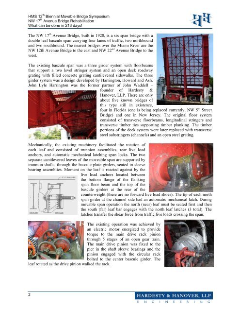
HMS 12 th Biennial Movable <strong>Bridge</strong> Symposium<strong>NW</strong> 17 th <strong>Avenue</strong> <strong>Bridge</strong> <strong>Rehabilitation</strong>What can be done in 213 days!The <strong>NW</strong> 17 th <strong>Avenue</strong> <strong>Bridge</strong>, built in 1928, is a six span bridge with adouble leaf bascule span carrying four lanes of traffic, two northboundand two southbound. The nearest bridges over <strong>the</strong> <strong>Miami</strong> <strong>River</strong> are <strong>the</strong><strong>NW</strong> 12th <strong>Avenue</strong> <strong>Bridge</strong> to <strong>the</strong> east and <strong>NW</strong> 22 nd <strong>Avenue</strong> <strong>Bridge</strong> to <strong>the</strong>west.The existing bascule span was a three girder system with floorbeamsthat support a two level stringer system and an open deck roadwaygrating with filled concrete grating cantilevered sidewalks. The threegirder system was a design developed by Harrington, Howard and Ash.John Lyle Harrington was <strong>the</strong> former partner of John Waddell –founder of Hardesty &Hanover, LLP. There are onlyabout five known bridges ofthis type still in existence,four in Florida (one is being replaced currently, <strong>NW</strong> 5 th Street<strong>Bridge</strong>) and one in New Jersey. The original floor systemconsisted of transverse floorbeams, longitudinal stringers andtransverse timber ties supporting timber planking. The timberportions of <strong>the</strong> deck system were later replaced with transversesteel substringers (channels) and an open steel grating.Mechanically, <strong>the</strong> existing machinery facilitated <strong>the</strong> rotation ofeach leaf and consisted of trunnion assemblies, rear live loadanchors, and automatic mechanical latching span locks. The twoseparate cantilevered leaves of <strong>the</strong> moveable span are supported bytrunnion shafts, through <strong>the</strong> bascule plate girders, seated in sleevebearing assemblies. Moment on <strong>the</strong> leaf is reacted against by <strong>the</strong>live load anchors located between<strong>the</strong> bottom flange of <strong>the</strong> flankingspan floor beam and <strong>the</strong> top of <strong>the</strong>bascule girders at <strong>the</strong> rear of <strong>the</strong>counterweight (<strong>the</strong>re are no forward live load shoes). The tip of each northspan girder at <strong>the</strong> channel side had an automatic mechanical latch. Duringmovable span operation <strong>the</strong> north (near) leaf must be seated first and <strong>the</strong>n<strong>the</strong> south (far) leaf bar engages with <strong>the</strong> north leaf latches (3 total). Thelatches transfer <strong>the</strong> shear force from traffic live loads crossing <strong>the</strong> span.The existing operation was achieved byan electric motor energized to providetorque to <strong>the</strong> main drive rack pinionthrough 5 stages of an open gear train.The main drive pinion was fixed to <strong>the</strong>pier in <strong>the</strong> shaft sleeve bearings and <strong>the</strong>pinion engaged with <strong>the</strong> circular rackbolted to <strong>the</strong> center bascule girder. Theleaf rotated as <strong>the</strong> drive pinion walked <strong>the</strong> rack.2


