Sanitary Sewage Pump Stations - The City of Wentzville | Missouri
Sanitary Sewage Pump Stations - The City of Wentzville | Missouri
Sanitary Sewage Pump Stations - The City of Wentzville | Missouri

Create successful ePaper yourself
Turn your PDF publications into a flip-book with our unique Google optimized e-Paper software.
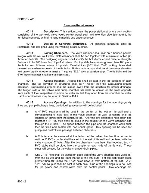
SECTION 401Structure Requirements401.1 Description. This section covers the pump station structure constructionconsisting <strong>of</strong> the wet well, valve vault, control panel pad, and retention pipe (storage) to befurnished complete with all jointing materials and appurtenances.401.2 Design <strong>of</strong> Concrete Structures. All concrete structures shall bereinforced, and designed using the Working Stress Method.401.3 Joining Chambers. <strong>The</strong> valve chamber shall rest on a haunch pouredintegral with the wet well walls. Both chambers shall be tied together with a minimum <strong>of</strong> two (2)threaded tie bolts. <strong>The</strong> designing engineer shall specify the bolt diameter and material strength.Bolts are to be 18” down from top <strong>of</strong> structure. For top slab thicknesses greater than 10”, placethe bolts down 6” from bottom <strong>of</strong> top slab. One-half inch (1/2”) thick 6”x6” backing plates shallbe used as washers on each <strong>of</strong> the tie bolts. Both structure tops shall be at the same elevationand drawn tightly together against a 1” square “E.Z.” stick expansion strip. <strong>The</strong> tie bolts and the6”x6” backing plates shall be stainless steel.401.4 Access Hatches. Access lids shall be cast in the top sections <strong>of</strong> eachchamber. <strong>The</strong> top elevation <strong>of</strong> structures shall be 1” higher than the surrounding groundelevation. Surrounding ground shall be sloped away from the structure for proper drainage.<strong>The</strong> hinged side <strong>of</strong> the valves and pump chamber lids shall be located on the walls oppositefrom each <strong>of</strong> their respective common tie walls so that they open from the chamber tie walls.Hatch specifications may be found in Section 404.7.401.5 Access Openings. In addition to the openings for the incoming gravitylines and pump discharge lines, the following accesses will be included:a. A 4” PVC coupler shall be cast in the center <strong>of</strong> the wet pit tie wall and acorresponding 6” hole cast in the valve chamber tie wall; centerline shall belocated 20” down from the structure top. After the two chambers have been tiedtogether a 4” PVC stub shall be glued in the coupler on the valve chamber sidethrough the 6” hole. <strong>The</strong> space between the pipe and the chamber walls shallthen be filled and sealed with non shrink grout. This opening will be used forpump and control wire passage between chambers.b. A 6” hole shall be centered at the bottom <strong>of</strong> the valve chamber floor in the tiewall. A 4” PVC coupler shall be cast in the wet pit tie wall and centered with thevalve chamber 6” hole. After the two chambers have been tied together, two 4”PVC stubs shall be glued into the coupler on each side <strong>of</strong> the tie wall. <strong>The</strong>sestubs will be used for the valve chamber drain piping.c. One 2-1/2” hole shall be placed on each side <strong>of</strong> the valve chamber side walls 18”from the tie wall and 18” from the top <strong>of</strong> the structure. For top slab thicknessesgreater than 10”, place the 2-1/2” holes down 8” from bottom <strong>of</strong> top slab. A 2-1/2” PVC coupler shall be cast in each hole. One <strong>of</strong> the openings is to be usedfor the power and control wires from the control panel. Two openings are400 - 2<strong>City</strong> <strong>of</strong> <strong>Wentzville</strong>Construction Specifications and Standard DetailsEffective Date: 06/10/09