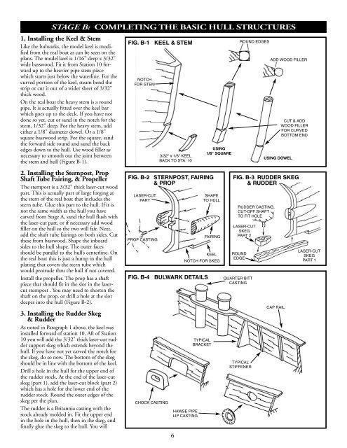
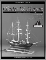
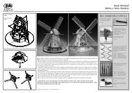
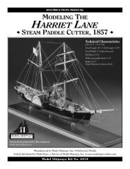
STAGE B: COMPLETING THE BASIC HULL STRUCTURES1. Installing the Keel & StemLike the bulwarks, the model keel is modifiedfrom the real boat as can be seen on theplans. The model keel is 1/16" deep x 3/32"wide basswood. Fit it from Station 10 forwardup to the heavier pipe stem piecewhich starts just below the waterline. For thecurved portion of the keel, steam bend thestrip or cut it out of a wider sheet of 3/32"thick wood.On the real boat the heavy stem is a roundpipe. It is actually fitted over the keel barwhich goes up to the deck. If you have notdone so yet, cut or sand in the notch for thestem, 1/32" deep. For the heavy stem, addeither a 1/8" diameter dowel. Or a 1/8"square basswood strip. For the square, sandthe forward side round and sand the backedges down to the hull. Use wood filler asnecessary to smooth out the joint betweenthe stem and hull (Figure B-1).2. Installing the Sternpost, PropShaft Tube Fairing, & PropellerThe sternpost is a 3/32" thick laser-cut woodpart. This is actually part of large forging atthe stern of the real boat that includes thestern tube. Glue this part to the hull. If it isnot the same width as the hull you havecarved from Stage A, sand the hull flush withthe laser-cut part, or if necessary add woodfiller on the hull so the two will fair. Next,add the shaft tube fairings on both sides. Cutthese from basswood. Shape the inboardsides to the hull shape. The outer facesshould be parallel to the hull’s centerline. Onthe real boat this is just a hump in the hullplating that covers the stern tube whichwould protrude thru the hull if not covered.Install the propeller. The prop has a shaftpiece that should fit in the slot in the lasercutsternpost . You may need to shorten theshaft on the prop, or drill a hole at the slotdeeper into the hull (Figure B-2).3. Installing the Rudder Skeg& RudderAs noted in Paragraph 1 above, the keel wasinstalled forward of station 10. Aft of Station10 you will add the 3/32" thick laser-cut ruddersupport skeg which extends beyond thehull. If you have not yet carved the notch forthe skeg, do so now. The bottom of the skegshould be in line with the bottom of the keel.Drill a hole in the hull for the upper end ofthe rudder stock. At the end of the laser-cutskeg (part 1), add the laser-cut block (part 2)which has a hole for the lower end of therudder stock. Round the outer edges of theskeg per the plan.The rudder is a Britannia casting with thestock already molded in. Fit the upper endin the hole in the hull, then in the skeg, andfinally glue the skeg to the hull. You willFIG. B-1 KEEL & STEMNOTCHFOR STEMFIG. B-2 STERNPOST, FAIRING& PROPLASER-CUTPARTPROP CASTINGFIG. B-4 BULWARK DETAILSCHOCK CASTING3/32" x 1/6" KEELBACK TO STA. 106SHAPETO HULLFAIRINGKEELNOTCH FOR SKEGHAWSE PIPELIP CASTINGTYPICALBRACKETUSING1/8" SQUAREROUND EDGESCUT & ADDWOOD FILLERFOR CURVEDBOTTOM ENDFIG. B-3 RUDDER SKEG& RUDDERRUDDER CASTING,CUT-OFF SHAFTTO FIT HOLELASER-CUTSKEGPART 2ROUNDEDGEQUARTER BITTCASTINGTYPICALSTIFFENERADD WOOD FILLERUSING DOWELCAP RAILLASER-CUTSKEGPART 1
FIG. B-5 PIPE FENDERSHALF-ROUNDCHAFING PIPESCLFIG. B-6 UPPER DECK & PILOT HOUSE TOPLASER-CUTUPPER DECKLASER-CUTPILOT HOUSE TOPSHAPE THEVISORSCUT FROM SHEET,ROUND OUTER EDGE1/8" HALF-ROUNDneed to cut off the bottom of the ruddershaft as it is too long to fit the hole in theskeg. Sounds complicated in words, butFigure B-3 will make it clear as mud.4. Cutting Out & Detailingthe Freeing PortsLayout the freeing ports in pencil first, thendrill several holes in the ports and file or sawout the port. The ports have vertical roundbars. Use brass wire or pins included in thekit for the bars. Installing the wire or pin is atricky task, so it is probably easier to drillholes down thru the top of the bulwark andinsert the wires or pins thru the holes. Cutthe heads off if pins are used.5. Installing Bulwark Brackets,Stiffeners, Cap Rail, Quarter Bitts,Chocks, & Hawse Pipe LipsBefore installing the cap rail, add the fourquarter bitts (Britannia castings - 2 eachside). Cut holes in the bulwark, one eachside, the shape of the bulwark chock castingsand glue them in place. Drill holes in thebulwark and add the Hawse pipe lip castings.The bulwark brackets and stiffenersshould be installed next. The bracket locationsare shown on the bulwark inboardprofile on the plan sheet 2 and the plan alsoshows details for the brackets as fitted on thereal boat as well as for the model. For themodel, the brackets are to be cut from 1/32"thick basswood. On the real boat, there is a1-1/2" diameter pipe welded to the inboardedge of the bracket plate, but that would bea little tedious for this scale model. Betweenthe brackets there are up to three equallyspaced flat bar stiffeners. For the model,use 1/32" square basswood to represent thestiffeners (Figure B-4).Finally, add the cap rail which is 1/32" x3/32" basswood. At the bow and stern wherethe rail curves quite a bit, cut the rail fromthe 1/32" basswood sheet in the kit. Fromjust aft of the aft quarter bitts, there is anotherrail on top of the cap rail going aroundthe stern. This is apparently a chafing rail fortowing lines. Use another 1/32" thick rail forthis piece. At the bow add the small platformbetween the rails.FIG. B-7 CABIN TRUNK, SKYLIGHT, & STACKSKYLIGHT BLOCKWITH 3 AIRPORTS6. Installing the OutboardPipe FendersThe outboard fenders on the real boat arehalf pipes. For the model, pre-sand 1/16" x1/8" wood strips to half-rounds and installthe strips. From Station 12 around the sternthe pipe transitions into a wider plate as canbe seen on the plan view. Cut this area fromthe 1/8" x 1/2" wood strip and sand theouter edge round to match the half roundfender forward. Between the cap rail andpipe fender at the stern install the three halfround chafing pipes. Figure B-5 illustratesthe fender details.EXHAUST RINGS,LASER-CUTSTACK TOP, LASER-CUTSTACK BLOCK(OVAL-SHAPED)CABIN TRUNK BLOCKSTRIP ON SIDES TOCREATE OVERHANGFORWARDPORTION OF VISOR,LASER-CUT7. Constructing the DeckhouseGeneral Makeup of the Deckhouse - Themachine-carved deckhouse consists of themain cabin and the captain’s cabin/pilothouse all in one piece. The top of the pilothouse including the visor is a laser-cut partin 3/32" basswood. The upper deck is alaser-cut part including a portion of the visorfrom the pilot house doors aft. The portionof the visor forward of the doors is also alaser-cut part. The raised area behind thecaptain's cabin (Cabin Trunk), the skylight,and the stack are rectangular wood blocksthat need to be shaped to some degree. Thetop of the stack is a laser-cut part.7