
Create successful ePaper yourself
Turn your PDF publications into a flip-book with our unique Google optimized e-Paper software.
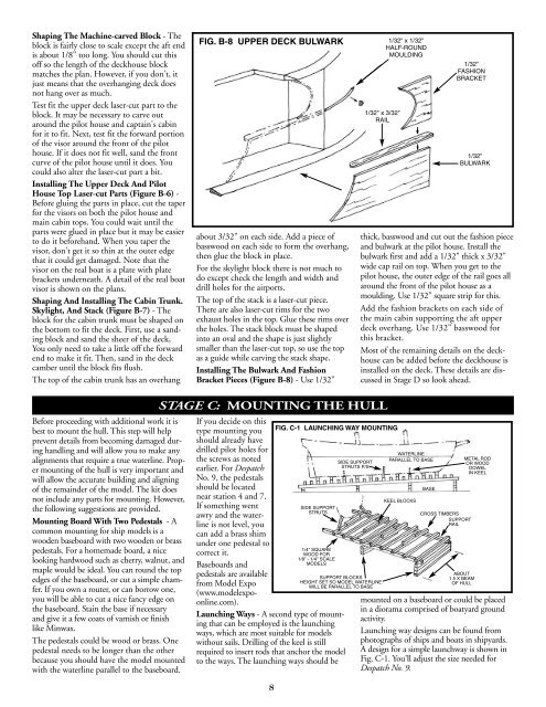
Shaping The Machine-carved Block - Theblock is fairly close to scale except the aft endis about 1/8" too long. You should cut thisoff so the length of the deckhouse blockmatches the plan. However, if you don't, itjust means that the overhanging deck doesnot hang over as much.Test fit the upper deck laser-cut part to theblock. It may be necessary to carve outaround the pilot house and captain's cabinfor it to fit. Next, test fit the forward portionof the visor around the front of the pilothouse. If it does not fit well, sand the frontcurve of the pilot house until it does. Youcould also alter the laser-cut part a bit.Installing The Upper Deck And PilotHouse Top Laser-cut Parts (Figure B-6) -Before gluing the parts in place, cut the taperfor the visors on both the pilot house andmain cabin tops. You could wait until theparts were glued in place but it may be easierto do it beforehand. When you taper thevisor, don't get it so thin at the outer edgethat it could get damaged. Note that thevisor on the real boat is a plate with platebrackets underneath. A detail of the real boatvisor is shown on the plans.Shaping And Installing The Cabin Trunk.Skylight, And Stack (Figure B-7) - Theblock for the cabin trunk must be shaped onthe bottom to fit the deck. First, use a sandingblock and sand the sheer of the deck,You only need to take a little off the forwardend to make it fit. Then, sand in the deckcamber until the block fits flush.The top of the cabin trunk has an overhangFIG. B-8 UPPER DECK BULWARK 1/32" x 1/32"HALF-ROUNDMOULDINGabout 3/32" on each side. Add a piece ofbasswood on each side to form the overhang,then glue the block in place.For the skylight block there is not much todo except check the length and width anddrill holes for the airports.The top of the stack is a laser-cut piece.There are also laser-cut rims for the twoexhaust holes in the top. Glue these rims overthe holes. The stack block must be shapedinto an oval and the shape is just slightlysmaller than the laser-cut top, so use the topas a guide while carving the stack shape.Installing The Bulwark And FashionBracket Pieces (Figure B-8) - Use 1/32"1/32" x 3/32"RAIL1/32"FASHIONBRACKET1/32"BULWARKthick, basswood and cut out the fashion pieceand bulwark at the pilot house. Install thebulwark first and add a 1/32" thick x 3/32"wide cap rail on top. When you get to thepilot house, the outer edge of the rail goes allaround the front of the pilot house as amoulding. Use 1/32" square strip for this.Add the fashion brackets on each side ofthe main cabin supporting the aft upperdeck overhang. Use 1/32" basswood forthis bracket.Most of the remaining details on the deckhousecan be added before the deckhouse isinstalled on the deck. These details are discussedin Stage D so look ahead.Before proceeding with additional work it isbest to mount the hull. This step will helpprevent details from becoming damaged duringhandling and will allow you to make anyalignments that require a true waterline. Propermounting of the hull is very important andwill allow the accurate building and aligningof the remainder of the model. The kit doesnot include any parts for mounting. However,the following suggestions are provided.Mounting Board With Two Pedestals - Acommon mounting for ship models is awooden baseboard with two wooden or brasspedestals. For a homemade board, a nicelooking hardwood such as cherry, walnut, andmaple would be ideal. You can round the topedges of the baseboard, or cut a simple chamfer.If you own a router, or can borrow one,you will be able to cut a nice fancy edge onthe baseboard. Stain the base if necessaryand give it a few coats of varnish or finishlike Minwax.The pedestals could be wood or brass. Onepedestal needs to be longer than the otherbecause you should have the model mountedwith the waterline parallel to the baseboard.STAGE C: MOUNTING THE HULLIf you decide on thistype mounting youshould already havedrilled pilot holes forthe screws as notedearlier. For DespatchNo. 9, the pedestalsshould be locatednear station 4 and 7.If something wentawry and the waterlineis not level, youcan add a brass shimunder one pedestal tocorrect it.Baseboards andpedestals are availablefrom Model Expo(www.modelexpoonline.com).Launching Ways - A second type of mountingthat can be employed is the launchingways, which are most suitable for modelswithout sails. Drilling of the keel is stillrequired to insert rods that anchor the modelto the ways. The launching ways should be8FIG. C-1 LAUNCHING WAY MOUNTINGSIDE SUPPORTSTRUTS1/4" SQUAREWOOD FOR1/8" - 1/4" SCALEMODELSSIDE SUPPORTSTRUTS P/SSUPPORT BLOCKSHEIGHT SET SO MODEL WATERLINEWILL BE PARALLEL TO BASEWATERLINEPARALLEL TO BASEKEEL BLOCKSBASECROSS TIMBERSSUPPORTRAILABOUT1.5 X BEAMOF HULLMETAL RODOR WOODDOWELIN KEELmounted on a baseboard or could be placedin a diorama comprised of boatyard groundactivity.Launching way designs can be found fromphotographs of ships and boats in shipyards.A design for a simple launchway is shown inFig. C-1. You'll adjust the size needed forDespatch No. 9.