Tool Holders - Hardinge
Tool Holders - Hardinge
Tool Holders - Hardinge

You also want an ePaper? Increase the reach of your titles
YUMPU automatically turns print PDFs into web optimized ePapers that Google loves.
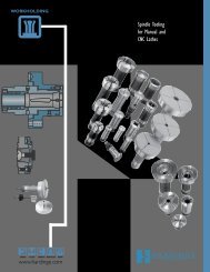
CHNC ® IIICHNC ® IIISPPage 4Miscellaneous <strong>Tool</strong>ing33MISCELLANEOUS TURRET TOP PLATE TOOL HOLDERS AND ACCESSORIES3435 363738394041424344454647484950515253Photo Model PageKey Number Description Number Number<strong>Tool</strong>s for Turret Top Plates and Vertical Slide33 Single <strong>Tool</strong> Holder C9 2334 Double <strong>Tool</strong> Holder C10 2335 Triple <strong>Tool</strong> Holder C20 2336 Invertible <strong>Tool</strong> Holder (Single Block) AHC33 2437 Invertible <strong>Tool</strong> Holder (Double Block) AHC34 2438 Invertible <strong>Tool</strong> Holder (Triple Block) AHC35 2439 Quadruple <strong>Tool</strong> Holder C5 2540 Universal <strong>Tool</strong> Post C28 2541 Boring <strong>Tool</strong> Holder C19 2642 Boring <strong>Tool</strong> Adapter AHC22 2643 Knurling <strong>Tool</strong> (Square Shank) — 2744 Multiple <strong>Tool</strong> Holder for Vertical Slide AHC6 2745 Cut-Off <strong>Tool</strong> Holder for Vertical Slide AHC13 2846 P3N Cut-Off Blade for Vertical Slide P3N 2847 <strong>Hardinge</strong>-Belcar Cut-Off Blade and Inserts G21 29Miscellaneous <strong>Tool</strong>s, Gages and Accessories48 Box <strong>Tool</strong> T12- 5 ⁄8" & T12- 3 ⁄4" 3049 Drill and Turn <strong>Tool</strong> Holder TH- 5 ⁄8" & TH- 3 ⁄4" 3050 Releasing Acorn Die Holder T10- 5 ⁄8" & T10- 3 ⁄4" 3151 Self-Feeding Die Holder SK11, 12, 21, 22 3152 Adjustable <strong>Tool</strong> Setting Gage N2 3253 <strong>Tool</strong> Setting Gage Bar — 32— Vertical Cut-Off Slide — 32— <strong>Tool</strong> Touch Probe — 33— Parts Removal System — 33— Mist Collector — 34— Chip Conveyor — 34— Voltage Transformers — 35— Collet Closer Foot Switch — 35— Spindle Reduction Liners — 36— Spindle Liner Kit — 36— One-Degree Spindle Orient — 37— Bar Feed Systems — 37— Spindle <strong>Tool</strong>ing — 37Call 800-843-8801Monday—Friday, 8:00 am to 8:00 pmEastern Standard Time for FAST delivery!<strong>Hardinge</strong> Inc.Elmira, New York 14902-1507 USA© <strong>Hardinge</strong> Inc., 2001All specifications subject to change without notice.Unless indicated otherwise, all marks indicated by ® and are trademarks of <strong>Hardinge</strong> Inc.
Interchangeable Top PlatesCHNC ® IIICHNC ® IIISPPage 5Interchangeable Turret Top Plates<strong>Hardinge</strong> ® CHNC Lathes complimented with interchangeable turret top plates have consistently reduced setup time. A wide range of tooling isoffered for use on the standard 8-station or optional 4-position gang-tooled turret top plates.The turret top plates are interchangeable, allowing an operator to remove a tooled top plate from a machine and replace it with another pre-tooledtop plate to reduce machine setup time. The top plate is secured to the machine by four screws.The gang-tooled turret top plate is ideal for maximum flexibility when setting up tool configurations. It can accommodate up to six tools per side,reducing the need to index frequently and improving cycle time up to 30%, especially for small parts in the range of 1" (25.40mm) in diameter andunder.PartNumberCN-0007214-ACN-0007214-BNC-0007214-1SCC-0007214-S8-Station Top Plates<strong>Tool</strong> <strong>Holders</strong>Used3⁄8" square and 5 ⁄8" round1⁄2" square and 3 ⁄4" round10mm square and 20mm round12mm square and 25mm roundMetric top plates: <strong>Tool</strong> holders must be purchased from manufacturersother than <strong>Hardinge</strong> ® .All tooling shown is optional.4-Position Gang-<strong>Tool</strong> Top PlatesPart<strong>Tool</strong> <strong>Holders</strong>Number UsedCN-0007214-D1 3⁄8" square and 5 ⁄8" roundCN-0007214-D1⁄2" square and 3 ⁄4" roundAll tooling shown is optional.© <strong>Hardinge</strong> Inc., 2001All specifications subject to change without notice.Unless indicated otherwise, all marks indicated by ® and are trademarks of <strong>Hardinge</strong> Inc.<strong>Hardinge</strong> Inc.Elmira, New York 14902-1507 USACall 800-843-8801Monday—Friday, 8:00 am to 8:00 pmEastern Standard Time for FAST delivery!
CHNC ® IIICHNC ® IIISPPage 6Extension <strong>Tool</strong> <strong>Holders</strong> & Cut-Type Knurling <strong>Tool</strong>Extension <strong>Tool</strong> Holder with Adjustable ShimThe extension tool holder is generally used for turning operations, but can also be used for holding toolsto back-face flanged work, or to cut off, knurl, groove, or thread a workpiece.The extension tool holder mounts directly into a T-slot of a turret top plate and uses 3 ⁄8" or 1 ⁄2" square shanktool bits for the respective top plate. Each holder features an adjustable wedge for adjusting the tool tocenter. Round shank tools can be held in these holders by using the AHC22 boring tool adapter.MZ 1W XNLETModel Part DimensionsNo. Number A C D E F L M N QCC13 CC-0008246-01 Inch 1.50 2.75 1.50 .500 2.00 1.75 .500 .520 .590mm 38.10 69.90 38.10 12.70 50.80 44.50 12.70 13.10 15.10CC14 CC-0008246-02 Inch 2.50 3.75 1.50 .500 2.00 1.75 .500 .520 .590mm 63.50 95.30 38.10 12.70 50.80 44.50 12.70 13.10 15.10CC15 CC-0008246-03 Inch 3.50 4.75 1.50 .500 2.00 1.75 .500 .520 .590mm 88.90 120.70 38.10 12.70 50.80 44.50 12.70 13.10 15.10CC16 CC-0008246-04 Inch 4.50 5.75 1.50 .500 2.00 1.75 .500 .520 .590mm 114.30146.10 38.10 12.70 50.80 44.50 12.70 13.10 15.10T – T-Bolt W – Washer X – Nut Z1– Set ScrewAH-0007241-L U-0004143 47-0001502-C 0570910DACHARDINGEELMIRA, N.Y., U.S.A.CC-14QF“Cut-Type” Diamond Knurling <strong>Tool</strong>The “cut-type” knurling tool is used to cut diamond knurls on a workpiece from 1 ⁄4" (6.35mm) to 6"(152.40mm) in diameter.The holder is supplied standard with two “cut-type” knurls (Part Number: ST-0010901-D). Theknurls have a 3 ⁄4" (19.05mm) OD, a 1 ⁄4" (6.35mm) ID, a width of 1 ⁄4" (6.35mm), and a 30 diametral pitch.The knurls are adjusted by rotating the shaft to which each knurl is mounted.The C30 and CC37 tool holders typically mount into an extension tool holder on 3 ⁄8" and 1 ⁄2" top plates,respectively.LCFModel Part DimensionsNo. Number A C E F L R SC30 AHB-0010901 Inch 1.63 2.44 .371 1.97 1.69 .380 1.22mm 41.30 61.90 9.43 50.00 42.90 9.50 31.00CC37 CCA-0010901 Inch 1.63 2.44 .497 2.25 1.69 .500 1.50mm 41.30 61.90 12.62 57.20 42.90 12.70 38.10ERSACall 800-843-8801Monday—Friday, 8:00 am to 8:00 pmEastern Standard Time for FAST delivery!<strong>Hardinge</strong> Inc.Elmira, New York 14902-1507 USA© <strong>Hardinge</strong> Inc., 2001All specifications subject to change without notice.Unless indicated otherwise, all marks indicated by ® and are trademarks of <strong>Hardinge</strong> Inc.
Cut-Off <strong>Tool</strong> Holder & High Speed Steel Cut-Off BladesCHNC ® IIICHNC ® IIISPPage 7Cut-Off <strong>Tool</strong> HolderThe cut-off holder mounts directly into an extension tool holder to perform cut-off operations from theturret. The cut-off holder comes supplied with a standard P1 1 ⁄16" (1.59mm) wide, high-speed, cut-offblade. Additional P2 and P3 blades are available in thicknesses of 3 ⁄32" (2.38mm) or 1 ⁄8" (3.18mm),respectively.Cutting from the turret has proven to be easier for holding length dimensions and for controlling thefeed rate.YNHLRFMACSModel Part DimensionsNo. Number A C F H L M N R SC31 ST-0011209 Inch 1.00 1.47 1.25 .477 1.50 .130 .480 .440 .470mm 25.40 37.30 31.80 12.12 38.10 3.20 12.20 11.10 11.90Y – Set Screw0100520The cut-off blade is for cutting or parting off material.It mounts directly into the C31 cut-off tool holder. Each blade is made of high-speed steeland can be resharpened as needed.Cut-Off BladesFHSCModel Part DimensionsNo. No. C F H SP1 P-0000001 Inch 4.50 .060 .477 .040mm 114.30 1.50 12.12 .900P2 P-0000002 Inch 4.50 .090 .477 .070mm 114.30 2.40 12.12 1.80P3 P-0000003 Inch 4.50 .130 .477 .100mm 114.30 3.20 12.12 2.60© <strong>Hardinge</strong> Inc., 2001All specifications subject to change without notice.Unless indicated otherwise, all marks indicated by ® and are trademarks of <strong>Hardinge</strong> Inc.<strong>Hardinge</strong> Inc.Elmira, New York 14902-1507 USACall 800-843-8801Monday—Friday, 8:00 am to 8:00 pmEastern Standard Time for FAST delivery!
CHNC ® IIICHNC ® IIISPPage 8<strong>Hardinge</strong>-Belcar Cut-Off <strong>Tool</strong> & InsertSquare Shank <strong>Hardinge</strong>-Belcar Cut-Off <strong>Tool</strong>The square shank <strong>Hardinge</strong>-Belcar cut-off tool is used to perform cut-off or groovingoperations.The holder mounts into a square shank tool holder. A light grip is required to place the insertinto the holder. The pressure of the first cut seats the insert and holds it tightly in the holder.The insert is removed from the holder using an extractor tool that is supplied as standard.The insert design causes chips to roll inward and form into flowing coils during the cuttingoperation. This design allows faster feed rates to be used for cut-off operations.A steady flow of coolant to the cutting edge is recommended.DW 1HModel Part Dimensions Hand InsertNo. Number W H L D(Max.)* No.G16 37A-0009639-02 Inch 3⁄8" 3 ⁄8" 2 1 ⁄2" 1 1 ⁄8" Right 2mm 9.52 9.52 63.50 28.58G18 50A-0009639-02 Inch 1⁄2" 1 ⁄2" 3" 1 11 ⁄16" Right 1mm 12.70 12.70 76.20 42.86G19 50A-0009639-03 Inch 1⁄2" 1 ⁄2" 3" 1 11 ⁄16" Left 3mm 12.70 12.70 76.20 42.86* Maximum diameter for solid workpieces. Tubing wall thickness may be half of maximum diameter.WLRight-hand model illustrated.<strong>Hardinge</strong>-Belcar Cut-Off InsertThe insert mounts directly into the <strong>Hardinge</strong>-Belcar cut-off tool holders. The inset configurationshapes the chips into narrow, easy-flowing coils, allowing heavier feeds and higherspindle speeds compared to conventional cut-off tools. The width of the insert and thediameter of the material determines feedrate and amount of stock removal.Since there are no wrenches, screws, loose clamps, or springs used, the cutting forcesincrease the grip of the insert by locking it firmly in place. The insert is easily removed usingthe extraction tool supplied with each cut-off tool. Inserts are purchased in packages of tenonly.Model Part Dimensions InsertNo. Number W1 Lead No. Hand.120" 3A-0010903-12 Inch .120 8° 1 Rightmm 3.05.093" 24A-0010903-09 Inch .093 8° 2 Rightmm 2.36.120" 3LA-0010903-12 Inch .120 8° 3 Leftmm 3.05Call 800-843-8801Monday—Friday, 8:00 am to 8:00 pmEastern Standard Time for FAST delivery!<strong>Hardinge</strong> Inc.Elmira, New York 14902-1507 USA© <strong>Hardinge</strong> Inc., 2001All specifications subject to change without notice.Unless indicated otherwise, all marks indicated by ® and are trademarks of <strong>Hardinge</strong> Inc.
Extension <strong>Tool</strong> <strong>Holders</strong>CHNC ® IIICHNC ® IIISPPage 9Left-Hand and Right-Hand Extension <strong>Tool</strong> Holder – 3 ⁄8" Top PlateThe extension holder is used to help balance the tool length in a turret setup and give additionalsupport for 3 ⁄8" left-hand and right-hand square shank tool bits that overhang the turret. Theycan be used for facing, turning, boring, chamfering, or threading operations.The extension holder mounts directly into a machine turret top plate T-slot.NZ 1CXWZ 1CXWFEMLAQTNEMFLAQTModel Part DimensionsNo. Number A C E F L M N QAHC24L AH-0011625-L Inch .910 2.00 .375 1.23 1.50 .500 .520 .590AHC25R AH-0011626-R mm 23.00 50.80 9.53 31.40 38.10 12.70 13.10 15.10T – T-Bolt W – Washer X – Nut Z 1 – Set ScrewHP-0007241 U-0004143 47-0001502-C 0570910Right-Hand and Left-Hand Extension <strong>Tool</strong> Holder – 1 ⁄2" Top PlateThe extension holder is used to help balance the tool length in a turret setup, and give additionalsupport for 1 ⁄2" right-hand or left-hand square shank tool bits that overhang the turret. They canbe used for facing, turning, boring, chamfering, or threading operations.The extension holder mounts directly into the machine turret top plate T-slot.Model Part DimensionsNo. Number A C E F L M N P QCC24L PL-0011625-L Inch .750 2.00 .500 1.25 1.50 .530 .560 .440 .630CC25R PL-0011625-R MM 19.10 50.80 12.70 31.80 38.10 13.50 14.30 11.10 15.90T – T-Bolt W – Washer X – Nut Z 1 – Set ScrewHP-0007241 U-0004143 47-0001502-C 0570908Z 1X Z 1WXWLE NN ELQTCAPFMMFPATCQ© <strong>Hardinge</strong> Inc., 2001All specifications subject to change without notice.Unless indicated otherwise, all marks indicated by ® and are trademarks of <strong>Hardinge</strong> Inc.<strong>Hardinge</strong> Inc.Elmira, New York 14902-1507 USACall 800-843-8801Monday—Friday, 8:00 am to 8:00 pmEastern Standard Time for FAST delivery!
CHNC ® IIICHNC ® IIISPPage 10Invertible Extension <strong>Holders</strong> & Adjustable ShimLeft-Hand and Right-Hand Invertible Extension <strong>Tool</strong> Holder – 3 ⁄8" & 1 ⁄2" Top PlateThe invertible tool holder is used to mount a 3 ⁄8" or 1 ⁄2" square shank tool for cutting on the rear or frontof the workpiece. The holder also helps balance the tool length in a turret setup and give additionalsupport for tools that overhang the turret.The holder mounts into the T-slot of a machine turret top plate. If the cutting tool is to be mounted forcutting on the rear of the workpiece, the tool is inverted and shimmed to place the cutting edge of thetool on the spindle centerline. Adjustable shims AHC36 for 3 ⁄8" tools or CC36 for 1 ⁄2" tools are requiredand purchased seperately. (Adjustable Shims are shown below.)FCCZ 1 YY Z 1FAHC-29CC-29AHC-30CC-30NLLNETTEMAAMModel Part DimensionsNo. Number A C E F L M NAHC29 KH-0011625-L Inch .750 1.75 .375 1.23 1.94 .500 .890AHC30 KH-0011626-R mm 19.10 44.50 9.52 31.30 49.20 12.70 22.60CC29 CC-0011625-L Inch .750 1.75 .500 1.25 2.00 .500 1.03CC30 CC-0011626-R mm 19.10 44.50 12.70 31.80 50.80 12.70 26.20T – Nut Y – Cap Screw Z 1 – Set ScrewST-0000374 0101028 AHC29/30 (0570912) & CC29/30 (0570910)Adjustable Shim For Invertible <strong>Tool</strong> <strong>Holders</strong>The adjustable shim is used to bring a tool’s cutting edge to the height of the spindle centerlineor as a spacer on top of a tool in an invertible tool holder.The shim is placed in the invertible tool holder under the square shank tool when it is used tocut on the rear of the workpiece.The thickness of the shim can be adjusted using the three screws built into the holder. Theadjustable shim can be set very quickly to the proper thickness by the operator.Model Part DimensionsNo. Number C E F LCC36 CC-0011760 Inch 1.88 .50 .50 .44MM 47.60 12.70 12.70 11.20AHC36 KH-0011760 Inch 1.88 .38 .38 .32MM 47.60 9.50 9.50 8.00Z 1 – Set ScrewCC36 (CH-000360) & AHC36 (KH-0010031)EFLCZ 1Call 800-843-8801Monday—Friday, 8:00 am to 8:00 pmEastern Standard Time for FAST delivery!<strong>Hardinge</strong> Inc.Elmira, New York 14902-1507 USA© <strong>Hardinge</strong> Inc., 2001All specifications subject to change without notice.Unless indicated otherwise, all marks indicated by ® and are trademarks of <strong>Hardinge</strong> Inc.
Left- & Right-Hand Drill and Shank <strong>Tool</strong> <strong>Holders</strong>CHNC ® IIICHNC ® IIISPPage 11Left-Hand Drill and Shank <strong>Tool</strong> Holder — 1 ⁄2" Top PlateThe left-hand drill and shank tool holder is used to hold tooling or other tool holders to performoperations such as center-drilling, drilling, turning, boring, reaming, and tapping.The holder mounts into the T-slot of a turret top plate and has a lip to locate against the face of the topplate for rigidity and to prevent the holder from shifting. HDB bushings may be used for holding smallershank size tools. (See page 16 for HDB bushings.)W X Z 1E MLHTAFPQCModel Part DimensionsNo. Number A C E F H-Bore L M P QCC19- 5 ⁄8 PL-0008257-62 Inch .130 1.50 .500 1.50 .625 1.25 1.13 1.06 .750mm 3.20 38.10 12.70 38.10 15.88 31.80 28.60 27.00 19.10CC19- 3 ⁄4 PLA-0008257-75 Inch .130 1.50 .500 1.50 .750 1.25 1.13 1.06 .750mm 3.20 38.10 12.70 38.10 19.05 31.80 28.60 27.00 19.10T – T-Bolt W – Washer X – Nut Z 1 – Set ScrewPL-0007241 FB-0006906 47-0001502-C 0570906Right-Hand Drill and Shank <strong>Tool</strong> Holder for 3 ⁄8" and 1 ⁄2" Top PlatesThe right-hand drill and shank tool holder is used to hold tooling or other tool holders to performoperations such as center-drilling, drilling, turning, boring, reaming, and tapping.The holder is mounted into the T-slot of a turret top plate and has a lip to locate against the face of thetop plate for rigidity and to prevent the holder from shifting. An HDB bushing may be used for smallershank size tooling. (See page 16 for HDB bushings.)CA1ZHLEWTX ZPQModel Part DimensionsNo. Number A C E F H-Bore L P QAHC21 AH-0008257 Inch .130 1.50 .375 1.50 .6253 1.00 .470 .750mm 3.20 38.10 9.53 38.10 15.883 25.40 11.90 19.10CC21- 5 ⁄8 PLA-0008256-62 Inch .130 1.50 .500 1.50 .6253 1.13 .440 .750mm 3.20 38.10 12.70 38.10 15.883 28.60 11.10 19.10CC21- 3 ⁄4 PLA-0008256-75 Inch .130 1.50 .500 1.50 .7503 1.13 .440 .750mm 3.20 38.10 12.70 38.10 19.058 28.60 11.10 19.10Model No. T – T-Bolt W – Washer X – Nut Z 1 – Set ScrewAHC21 HP-0007241 FB-0006906 47-0001502-C 0570906CC21- 5 ⁄8 PL-0007241 FB-0006906 47-0001502-C 0570906CC21- 3 ⁄4 PL-0007241 FB-0006906 47-0001502-C 0570906© <strong>Hardinge</strong> Inc., 2001All specifications subject to change without notice.Unless indicated otherwise, all marks indicated by ® and are trademarks of <strong>Hardinge</strong> Inc.<strong>Hardinge</strong> Inc.Elmira, New York 14902-1507 USACall 800-843-8801Monday—Friday, 8:00 am to 8:00 pmEastern Standard Time for FAST delivery!
Triple <strong>Tool</strong> HolderCHNC ® IIICHNC ® IIISPPage 13The triple tool holder is used to hold a maximum of three round shank tools in one tool holderto perform end-working operations such as drilling, boring, turning, reaming and tapping.The triple tool holder is mounted into the T-slot of a turret top plate and has a lip to locate againstthe face of the top plate for rigidity and to prevent the holder from shifting. This holder increasestooling versatility and allows for improved production because the top plate does not have to beindexed before performing the next round shank operation.An HDB bushing may be used for smaller shank size tooling.(See page 16 for HDB bushings.)Triple <strong>Tool</strong> Holder — 3 ⁄8" and 1 ⁄2" Top PlatesBushings and tooling not included with this tool holderWEXZ 1GHLAKQCPFTModel Part DimensionsNo. Number A C E F G H-Bore K L P QCC34- 5 ⁄8 CC-0008257-62 Inch .97 2.00 .375 2.88 .659 .6253 1.09 1.41 1.44 1.59for 3 ⁄8" Top Plate mm 24.60 50.80 9.53 73.00 16.73 15.883 27.70 35.70 36.50 40.50CC33- 3 ⁄4 CC-0008257-75 Inch .97 2.00 .500 2.88 .784 .7503 1.31 1.41 1.44 1.59for 1 ⁄2" Top Plate mm 24.60 50.80 12.70 73.00 19.90 19.058 33.30 35.70 36.50 40.50CC33- 5 ⁄8 CCA-0008257 Inch .97 2.00 .500 2.88 .659 .6253 1.31 1.41 1.44 1.59for 1 ⁄2" Top Plate mm 24.60 50.80 12.70 73.00 16.73 15.883 33.30 35.70 36.50 40.50T – T-Bolt W – Washer X – Nut Z 1 – Set ScrewHP-0007241 U-0004143 47-0001502-C 0570906© <strong>Hardinge</strong> Inc., 2001All specifications subject to change without notice.Unless indicated otherwise, all marks indicated by ® and are trademarks of <strong>Hardinge</strong> Inc.<strong>Hardinge</strong> Inc.Elmira, New York 14902-1507 USACall 800-843-8801Monday—Friday, 8:00 am to 8:00 pmEastern Standard Time for FAST delivery!
CHNC ® IIICHNC ® IIISPPage 14<strong>Tool</strong> Extension & Floating Reamer Holder<strong>Tool</strong> Holder ExtensionThe tool holder extension is used as a means to position smaller diameter drills on acommon plane with other tools in the same setup, reducing tool interference.The tool holder extension mounts directly into a round shank tool holder. It will extendround shank tools an additional 1 5 ⁄8" (41.28mm). (See page 16 for HDB bushings.)Drill and bushing not included.KZ 1CLHDGQABModel Part DimensionsNo. Number A B C D G H K L QTE- 5 ⁄8 ST-0011155 Inch 1.63 1.16 2.78 .6243 .310 .6252 1.25 1.50 .310mm 41.30 29.40 70.60 15.856 7.90 15.880 31.80 38.10 7.90TE- 3 ⁄4 ST-0011155-01 Inch 1.63 1.16 2.78 .7493 .310 .7502 1.25 1.50 .310mm 41.30 29.40 70.60 19.031 7.90 19.055 31.80 38.10 7.90Z 1 – Set Screw0570906Floating Reamer HolderThe floating reamer holder is used to align the tool with the hole being reamed.This holder mounts into a round shank tool holder and it floats freely, providingalignment of the reamer with the hole. The holder has a 1 ⁄2" (12.70mm) diameter boredhole for 1 ⁄2" round shank tools and will accept HDB-2 bushings for holding tools with 3 ⁄8"and smaller shanks. (See page 16 for HDB bushings.)F HDZ 1GModel Part DimensionsNo. Number A B C D F G H K LT19- 5 ⁄8 ST-0007967 Inch .840 1.13 1.97 .6243 1.98 .390 .5003 .660 1.00mm 21.40 28.60 50.00 15.856 50.40 9.90 12.706 16.70 25.40T19- 3 ⁄4 ST-0007967-01 Inch .840 1.13 1.97 .7493 1.98 .450 .5003 .660 1.00mm 21.40 28.60 50.00 19.031 50.40 11.50 12.706 16.70 25.40Z 1 – Set Screw0550704LKACBCall 800-843-8801Monday—Friday, 8:00 am to 8:00 pmEastern Standard Time for FAST delivery!<strong>Hardinge</strong> Inc.Elmira, New York 14902-1507 USA© <strong>Hardinge</strong> Inc., 2001All specifications subject to change without notice.Unless indicated otherwise, all marks indicated by ® and are trademarks of <strong>Hardinge</strong> Inc.
Adjustable <strong>Tool</strong> Holder & 1C Collet HolderCHNC ® IIICHNC ® IIISPPage 15Adjustable <strong>Tool</strong> HolderThe adjustable tool holder provides a means of adjusting center working tools such ascenter drills and drills to the centerline of the spindle. When the tool has been centered,the adjustable portion of the holder is locked into position.The holder mounts into a round shank tool holder and it has a 1 ⁄2" (12.70mm) diameter boreto hold round shank tools. HDB-2 bushings can be used in the holder to hold tools withshanks that are 3 ⁄8" or less in diameter. (See next page for HDB bushings.)Y WZ 1FDHGLKACBModel Part DimensionsNo. Number A B C D F G H K LOOD- 5 ⁄8 OO-0007967 Inch .840 1.34 2.19 .6245 1.84 .375 .5002 .690 1.00mm 21.40 34.00 55.50 15.862 46.80 9.53 12.705 17.50 25.40OOD- 3 ⁄4 OO-0007967-01 Inch .840 1.34 2.19 .7500 1.84 .375 .5002 .690 1.00mm 21.40 34.00 55.50 19.050 46.80 9.53 12.705 17.50 25.40Z 1 – Set Screw05507041C Collet HolderThis 1C collet-type tool holder is an accurate method of holding drills, center drills, roundshank boring bars, round shank turning tools and reamers.The T17 holder mounts directly into a round shank tool holder. The holder is hardened andground and holds standard 1C collets, which have a maximum capacity of 1 ⁄4" (6.35mm).Turning a nut at the rear of the assembly draws the collet into the assembly, where thematching angles of the collet and the holder cause the collet to close down on the tool.(See Brochure #2351 for 1C collets.)Drill and 1C collet not included.NMCDGModel Part DimensionsNo. Number C D G M NT17- 5 ⁄8 37-0000102 Inch 1.82 .6243 .30 .25 .54mm 20.80 15.856 7.60 6.40 13.70T17- 3 ⁄4 37-000102-01 Inch 1.82 .7493 .30 .25 .54mm 20.80 19.031 7.60 6.40 13.70© <strong>Hardinge</strong> Inc., 2001All specifications subject to change without notice.Unless indicated otherwise, all marks indicated by ® and are trademarks of <strong>Hardinge</strong> Inc.<strong>Hardinge</strong> Inc.Elmira, New York 14902-1507 USACall 800-843-8801Monday—Friday, 8:00 am to 8:00 pmEastern Standard Time for FAST delivery!
CHNC ® IIICHNC ® IIISPPage 16DimensionsAB<strong>Hardinge</strong> Bushing OverallStyle Part Number Figure Diameter Length Type Size Range<strong>Tool</strong>holder Bushings (HDB2, HDB5 & HDB6)1⁄2" 3⁄4"HDB 2 1763-00-19 1 (12.70) (19.05) Fractional 1⁄32" to 3 ⁄8" inclusive by 1 ⁄64" incrementsKit 0937-00-19 Fractional 23 Bushings from 1 ⁄32" to 3 ⁄8" by 1 ⁄64" Incr.1⁄2" 3⁄4"HDB 2 1763-00-18 1 (12.70) (19.05) Decimal .141", .168", .194", .220", .255", .318", .323", .367", .381"1⁄2" 3⁄4"HDB 2 1763-00-17 1 (12.70) (19.05) Metric 1.0mm to 5.0mm inclusive by .2mm increments1⁄2" 3⁄4"HDB 2 1763-00-16 1 (12.70) (19.05) Letter A to V inclusiveKit 0937-00-16 Letter 22 Bushings from A thru V1⁄2" 3⁄4"HDB 2 1763-00-15 1 (12.70) (19.05) Number 1 to 67 inclusiveKit 0937-00-15 Number 67 Bushings from #1 thru #675⁄8" 1 1 ⁄8"HDB 5 1765-00-19 1 (15.88) (26.20) Fractional 1⁄32" to 1 ⁄2" inclusive by 1 ⁄64" incrementsKit 0938-00-19 Fractional 31 Bushings from 1 ⁄32" to 1 ⁄2" by 1 ⁄64"5⁄8" 1 1 ⁄8"HDB 5 1765-00-17 1 (15.88) (26.20) Metric 1.0mm to 13.0mm inclusive by .5mm increments5⁄8" 1 1 ⁄8"HDB 5 1765-00-16 1 (15.88) (26.20) Letter A to Z inclusiveKit 0938-00-16 Letter 26 Bushings from A thru Z5⁄8" 1 1 ⁄8"HDB 5 1765-00-15 1 (15.88) (26.20) Number 1 to 52 inclusiveKit 0938-00-15 Number 52 Bushings from #1 thru #523⁄4" 1 1 ⁄8"HDB 6 1881-00-19 1 (19.05) (28.58) Fractional 1⁄16" to 5 ⁄8" inclusive by 1 ⁄64" incrementsKit 0939-00-19 Fractional 37 Bushings from 1 ⁄16" to 5 ⁄8" by 1 ⁄64"3⁄4" 1 1 ⁄8"HDB 6 1881-00-17 1 (19.05) (28.58) Metric 2.0mm to 16.0mm inclusive by .5mm increments3⁄4" 1 1 ⁄8"HDB 6 1881-00-16 1 (19.05) (28.58) Letter A to Z inclusiveKit 0939-00-16 Letter 26 Bushings from A thru Z3⁄4" 1 1 ⁄8"HDB 6 1881-00-15 1 (19.05) (28.58) Number 1 to 52 inclusiveKit 0939-00-15 Number 52 Bushings from #1 thru #52NOTE: Millimeters in parentheses.1ABCall 800-843-8801Monday—Friday, 8:00 am to 8:00 pmEastern Standard Time for FAST delivery!<strong>Hardinge</strong> Inc.Elmira, New York 14902-1507 USA© <strong>Hardinge</strong> Inc., 2001All specifications subject to change without notice.Unless indicated otherwise, all marks indicated by ® and are trademarks of <strong>Hardinge</strong> Inc.
Double-Angle Collet <strong>Tool</strong> HolderCHNC ® IIICHNC ® IIISPPage 17The Double-Angle (DA) Collet Extension <strong>Tool</strong> Holder mounts directly into a round shank toolholder. The DAH model holders will accept DA200 or DA300 collets (See Brochure #2351 forcollets).Optional qualifying collars and chuck stops are available. The collars position and lock on theholder shank to qualify the tool's position in the DAH holder. Chuck stops are positioned insidethe holder body to provide a qualified locating stop for tooling and help to prevent tool “pushback”.Double-Angle Collet Extension <strong>Tool</strong> HolderShown with optional collet.Collet Model Shank Length Cap Cap Qualifying Collar Drill StopStyle Number Part Number A B C E Part Number Hex Part Number Part NumberDA300 DAH330 1925-00-00-000000 .500" 2.188" 3.50" .560" 1933-00-00-000000 1⁄2" 1941-00-00-000000 1939-00-00-000000DA300 DAH350 1927-00-00-000000 .500" 4.188" 5.50" .560" 1933-00-00-000000 1⁄2" 1941-00-00-000000 1939-00-00-000000DA300 — 7996-03-30-005000 .500" 5.500" 6.79" .560" 7991-03-30-000001 1⁄2" — 7990-03-30-000004DA300 DAH335 1943-00-00-000000 .625" 2.188" 3.50" .680" 1951-00-00-000000 5⁄8" 1957-00-00-000000 1939-00-00-000000DA300 DAH355 1945-00-00-000000 .625" 4.188" 5.50" .680" 1951-00-00-000000 5⁄8" 1957-00-00-000000 1939-00-00-000000DA200 DAH255 1959-00-00-000000 .750" 1.875" 3.50" .812" 1967-00-00-000000 11 ⁄16" 1975-00-00-000000 1973-00-00-000000DA200 DAH235 1961-00-00-000000 .750" 3.875" 5.50" .812" 1967-00-00-000000 11 ⁄16" 1975-00-00-000000 1973-00-00-000000DA200 — 7996-03-20-007500 .750" 5.500" 7.23" .860" 7991-03-20-000001 3⁄4" — 7990-03-20-000004Drill StopQualifying Collar© <strong>Hardinge</strong> Inc., 2001All specifications subject to change without notice.Unless indicated otherwise, all marks indicated by ® and are trademarks of <strong>Hardinge</strong> Inc.<strong>Hardinge</strong> Inc.Elmira, New York 14902-1507 USACall 800-843-8801Monday—Friday, 8:00 am to 8:00 pmEastern Standard Time for FAST delivery!
CHNC ® IIICHNC ® IIISPPage 18"Crush- & Cut-Type" Knurling <strong>Tool</strong>s“Crush-Type” Knurling <strong>Tool</strong>The knurling tool mounts into a round shank tool holder and comes standard with twoknurls. The 64 diametrical pitch knurling wheels are mounted into swivel holders that canbe set at any angle to form either diamond or straight knurls. This unit can knurl aworkpiece using a cross slide motion (approaching the work perpendicularly), or aturning motion by placing the holder parallel to the workpiece and passing the workpiecebetween the knurls.By making the appropriate adjustments, diameters from 5 ⁄32" to 1 ⁄2" (3.97 to 12.70mm) forthe T8- 5 ⁄8 model and to 3 ⁄4" (19.05mm) for the T8- 3 ⁄4 model can be knurled. A workpiecewith a diameter of 3 ⁄8" (9.53mm) or less can pass through the shank of the knurling tool.For stock diameters of 3 ⁄8" to 1 ⁄2" (9.53 to 12.70mm), the maximum knurling length is 7 ⁄8"(22.23mm).30L003 04 5WZYModel Part DimensionsNo. Number A B C D G H K L QT8- 5 ⁄8 STA-0010901 Inch 1.63 1.13 2.75 .6243 2.06 .390 .5002 .500 1.00mm 41.30 28.60 69.90 15.857 52.40 9.90 12.704 12.70 25.40T8- 3 ⁄4 STA-0010901-75 Inch 2.44 1.49 3.93 .7493 2.80 .450 .6252 .800 1.38mm 61.90 37.90 99.80 19.031 71.00 11.30 15.879 20.30 35.10W – Washer X – Cutting Wheels Y – Cap Screw Z 1 – Set Screw3-0010901 T8- 5 ⁄8 (8-0010901) & T8- 3 ⁄4 (ST-0010901) 0100208 0550506FXHAKCBGD“Cut-Type” Straight Knurling <strong>Tool</strong>The “cut-type” straight knurling tool is used to generate a straight knurl by cutting themetal.The tool holder shaft mounts into a 5 ⁄8" round shank tool holder and comes standard withone knurl. The knurl has a 3 ⁄4" (19.05mm) OD and 1 ⁄4" (6.35mm) ID with a width of 1 ⁄4"(6.35mm).YModel Part DimensionsNo. Number B C D EAHC31 KH-0011762 Inch 2.25 2.63 .624 .500mm 57.20 66.70 15.85 12.70Y – Cutting WheelsST-0010901-DECBDCall 800-843-8801Monday—Friday, 8:00 am to 8:00 pmEastern Standard Time for FAST delivery!<strong>Hardinge</strong> Inc.Elmira, New York 14902-1507 USA© <strong>Hardinge</strong> Inc., 2001All specifications subject to change without notice.Unless indicated otherwise, all marks indicated by ® and are trademarks of <strong>Hardinge</strong> Inc.
Adjustable & Revolving StopsCHNC ® IIICHNC ® IIISPPage 19The revolving stock stop is used in a round shank tool holder to position bar stock in thecollet while being fed by a bar feed unit. The front portion of the stop rotates with theworkpiece.The adjustable stop has a maximum length adjustment of 7 ⁄8" (22.23mm).Adjustable Revolving Stock StopLDABModel Part DimensionsNo. Number Min A Max A B D LT20- 5 ⁄8 RSA-0011157 Inch .750 1.63 1.13 .624 .810mm 19.10 41.30 28.60 15.85 20.60T20- 3 ⁄4 RSA-0011157-01 Inch .750 1.63 1.13 .749 .810mm 19.10 41.30 28.60 19.03 20.60The revolving stock stop mounts into a round shank tool holder directly, or with a bushing,to position bar stock in the collet while being fed by a bar feed unit. The front portion ofthe stop rotates with the workpiece.Revolving Stock StopLDACBModel Part DimensionsNo. Number A B C D LT20- 3 ⁄4-16 RS-0011157-16 Inch 1.06 1.38 2.44 .749 1.44mm 27.00 34.90 61.90 19.04 36.50© <strong>Hardinge</strong> Inc., 2001All specifications subject to change without notice.Unless indicated otherwise, all marks indicated by ® and are trademarks of <strong>Hardinge</strong> Inc.<strong>Hardinge</strong> Inc.Elmira, New York 14902-1507 USACall 800-843-8801Monday—Friday, 8:00 am to 8:00 pmEastern Standard Time for FAST delivery!
CHNC ® IIICHNC ® IIISPPage 20Interchangeable Bar Pullers & AdaptersInterchangeable Bar Pullers and AdaptersBar Stock Pullers<strong>Hardinge</strong> ® bar stock pullers are an economical, accurate way to pull round bar stockthrough a spindle. They are also ideal for using up short pieces of bar stock, or whenoperating floor space is limited. The pullers are mounted into or round shank tool holderand are stocked in sizes that range from 5 ⁄16" (7.9mm) to 1 5 ⁄8" (41.3mm) in1⁄16" (1.59mm) increments. They can be interchanged easily between the three adaptershank sizes shown. Overhang from the turret or the face of the round shank tool holderis 3 11 ⁄16" (93.7mm) for minimal tool interference.Bar StockPuller AdaptersCollet Part No.17170319003125171703190037501717031900437517170319005000171703190056251717031900625017170319006875171703190075001717031900812517170319008750171703190098751717031901000017170319010625171703190112501717031901187517170319012500171703190131251717031901375017170319014375171703190150001717031901562517170319016250DimensionsA B C D F H-BoreInch 2.88 .63 3.50 1.484-24 1.75 .3125mm 73.0 15.9 88.9 37.69-24 44.5 7.937Inch 2.88 .63 3.50 1.484-24 1.75 .3750mm 73.0 15.9 88.9 37.69-24 44.5 9.525Inch 2.88 .63 3.50 1.484-24 1.75 .4375mm 73.0 15.9 88.9 37.69-24 44.5 11.116Inch 2.88 .63 3.50 1.484-24 1.75 .5000mm 73.0 15.9 88.9 37.69-24 44.5 12.700Inch 2.88 .63 3.50 1.484-24 1.75 .5625mm 73.0 15.9 88.9 37.69-24 44.5 14.288Inch 2.88 .63 3.50 1.484-24 1.75 .6250mm 73.0 15.9 88.9 37.69-24 44.5 15.875Inch 2.88 .63 3.50 1.484-24 1.75 .6875mm 73.0 15.9 88.9 37.69-24 44.5 17.463Inch 2.88 .63 3.50 1.484-24 1.75 .7500mm 73.0 15.9 88.9 37.69-24 44.5 19.05Inch 2.88 .63 3.50 1.484-24 1.75 .8125mm 73.0 15.9 88.9 37.69-24 44.5 20.638Inch 2.88 .63 3.50 1.484-24 1.75 .8750mm 73.0 15.9 88.9 37.69-24 44.5 22.225Inch 2.88 .63 3.50 1.484-24 1.75 .9875mm 73.0 15.9 88.9 37.69-24 44.5 25.083Inch 2.88 .63 3.50 1.484-24 1.75 1.0000mm 73.0 15.9 88.9 37.69-24 44.5 25.400Inch 2.88 .63 3.50 1.484-24 1.75 1.0625mm 73.0 15.9 88.9 37.69-24 44.5 26.988Inch 2.88 .63 3.50 1.484-24 1.75 1.1250mm 73.0 15.9 88.9 37.69-24 44.5 28.575Inch 2.88 .63 3.50 1.484-24 1.75 1.1875mm 73.0 15.9 88.9 37.69-24 44.5 30.163Inch 2.88 .63 3.50 1.484-24 1.75 1.2500mm 73.0 15.9 88.9 37.69-24 44.5 31.750Inch 2.88 .63 3.50 1.484-24 1.75 1.3125mm 73.0 15.9 88.9 37.69-24 44.5 33.338Inch 2.88 .63 3.50 1.484-24 1.75 1.3750mm 73.0 15.9 88.9 37.69-24 44.5 34.925Inch 2.88 .63 3.50 1.484-24 2.13 1.4375mm 73.0 15.9 88.9 37.69-24 54.0 36.513Inch 2.88 .63 3.50 1.484-24 2.13 1.5000mm 73.0 15.9 88.9 37.69-24 54.0 38.1Inch 2.88 .63 3.50 1.484-24 2.13 1.5625mm 73.0 15.9 88.9 37.69-24 54.0 39.688Inch 2.88 .63 3.50 1.484-24 2.13 1.6250mm 73.0 15.9 88.9 37.69-24 54.0 41.275Adapter PartDimensionsNo. A B C D F17170600000000 Inch .810 1.28 2.09 .625 1.75mm 20.60 32.50 53.10 15.88 44.5017170500000000 Inch .810 1.28 2.09 .750 1.75mm 20.60 32.50 53.10 19.05 44.50Note: Spindle Reduction Liners must be used in the draw tube of the spindle when using Bar Pullers.Spindle Liner Kit – Part Number: HFSS25, HFSS30, HFSS35, HFCC42, HFCC46Call 800-843-8801Monday—Friday, 8:00 am to 8:00 pmEastern Standard Time for FAST delivery!<strong>Hardinge</strong> Inc.Elmira, New York 14902-1507 USA© <strong>Hardinge</strong> Inc., 2001All specifications subject to change without notice.Unless indicated otherwise, all marks indicated by ® and are trademarks of <strong>Hardinge</strong> Inc.
Bar Stock PullerCHNC ® IIICHNC ® IIISPPage 21Bar Stock PullerThe combination round/square shank bar stock puller is ideal for using up short pieces ofbar stock or when operating floor space is limited. The puller is mounted into an invertiblesquare shank tool holder.• Grips stock up to 1 5 ⁄8" (42mm) diameter — simple screw adjustment• Grips round, hex, square and octagon stock with optional caps• Quick set-up time and adjustment• Grips close to collet — 1 ⁄8" (3.2mm) from face• Short overhang from the turret top plate for minimal tool interference• Eliminate inventory of feed fingers and pullers• Self-centering gripper adjustment• Eliminates shock from hydraulic feedersD'AEBDCCaps Required for Hex/Square WorkShown with optional cap for pulling hex & square stock.Capacity - Hex & Square StockModel Max. Hex/Square CapsC100 1 9 ⁄32" OneModel Part DimensionsNo. Number A B C D D 1 E RC100 1821-00-00-000000 Inch 1.50 1.00 2.50 2.06 2.16 .750 0 to 1.50mm 38.10 25.40 63.50 52.40 54.30 19.10 0 to 38.10Jaw Caps for Hex, Square and Tailstock WorkPuller Jaw Cap Jaw Cap Jaw CapsModel Part No. Style RequiredC100 1821-00-00-000007 Short Models C100 require one long jaw cap.1821-00-00-000010 LongNote: Spindle Reduction Liners must be used in the draw tube of the spindle when using Bar Pullers.Spindle Liner Kit – Part Number: HFSS25, HFSS30, HFSS35, HFCC42, HFCC46© <strong>Hardinge</strong> Inc., 2001All specifications subject to change without notice.Unless indicated otherwise, all marks indicated by ® and are trademarks of <strong>Hardinge</strong> Inc.<strong>Hardinge</strong> Inc.Elmira, New York 14902-1507 USACall 800-843-8801Monday—Friday, 8:00 am to 8:00 pmEastern Standard Time for FAST delivery!
CHNC ® IIICHNC ® IIISPPage 22"Collet-Type" Releasing & Self Feeding Tap <strong>Holders</strong>"Collet-Type" Releasing Tap HolderThe collet-type releasing tap holder is used to provide thread length control on either rightorleft-hand taps by switching a lever inside the body of the tap holder.Tap and colletnot included.The tap holder mounts directly into a round shank tool holder. “TT” style tap holder colletsare used to accurately hold and center taps. To provide a positive drive for the taps, thecollets have a square slot in the back to accommodate the square of the top shank and anotch in the back bearing of the collet that fits over a hardened pin in the bottom of theholder. (See Brochure #2351 for “TT” tap holder collets.)Model Part DimensionsNo. Number A B C D FTT- 5 ⁄8 STA-0011202 Inch 2.22 1.25 3.47 .624 1.63mm 56.40 31.80 88.10 15.85 41.30TT- 3 ⁄4 STA-0011202-01 Inch 2.22 1.25 3.47 .749 1.63mm 56.40 31.80 88.10 19.03 41.30FACBDSelf-Feeding Tap HolderThe self-feeding tap holder provides automatic thread length control. The tap holder eliminatesthe need to match feed rate to thread pitch, minimizing tool breakage and “pulled” or “squeezed”threads.The holder has a 5 ⁄8" shank diameter that allows it to be mounted into a round shank tool holder.Thread length is controlled internally with an adjusting ring in .01" (.25mm) increments. A driveris used in the holder to accommodate the square of the tap shank, providing a positive drive.A collet is used to centralize and hold the tap in the holder. Tap holders are supplied standardwith the necessary collets and drivers. Replacement tap collets and drivers are sold separately.FLDThe same unit is used for left- and right-hand taps. The GK11 and GK12 models include threetap collets and four drivers. The GK21 and GK22 include six tap collets and six drivers.ATap Collets and DriversModel Tap Size Shank Collet Tap Diver Collet/DriverNo. Eng. Metric Dia No. Sq. No. Part No.GK11/12 6 1.6 .141 4-3.5 .110 2.8 1T0011831C1*/D1*GK11/12 8 4 .168 5-4 .131 3.55 1T0011831C2*/D2*GK11/12 10 4.5-5 .194 5-4 .152 4 1T0011831C2*/D2*GK11/12 12 — .220 6.5-5.5 .165 4 1T0011831C3*/D3*GK11/12 14 6 .255 6.5-5.5 .191 5 1T0011831C3*/D4*GK11/12 1⁄4" — .255 6.5-5.5 .191 5 1T0011831C3*/D4*GK21/22 8 4 .168 5-4 .131 3.55 2T0011831C1*/D1*GK21/22 10 4.5-5 .194 5-4 .152 4 2T0011831C2*/D2*GK21/22 12 — .220 6-5 .165 4 2T0011831C2*/D2*GK21/22 14 6 .255 7-6 .191 5 2T0011831C3*/D3*GK21/22 1⁄4" 6.3 .255 7-6 .191 5 2T0011831C3*/D3*GK21/22 5⁄16" 7-8 .318 9-8 .238 6.3 2T0011831C4*/D4*GK21/22 3⁄8" 10 .381 10-9 .286 7.1 2T0011831C5*/D6*GK21/22 7⁄16" — .323 9-8 .242 6.3 2T0011831C4*/D4*GK21/22 1⁄2" 12-12.5 .367 10-9 .274 7.1 2T0011831C5*/D6*GK21/22 9⁄16" 14 .429 11-10 .322 8 2T0011831C6/D7** Collets and Drivers furnished with Tap HolderCBMaximumModel Maximum Thread LengthNo. Tap Size AdjustmentGK11 1⁄4" (6.35mm)25⁄32" (19.84mm)GK12 1⁄4" (6.35mm)19⁄32" (15.08mm)GK21 9⁄16" (14.29mm)27⁄32" (21.43mm)GK22 9⁄16" (14.29mm)19⁄32" (15.08mm)Model Part DimensionsNo. Number A B C D F LGK11 K11-0011202-K Inch 2.17 1.25 3.42 .625 1.58 .770mm 55.10 31.80 86.90 15.88 40.10 19.60GK12 S12-0011202-K Inch 1.89 1.25 3.14 .625 1.58 .770mm 48.00 31.80 79.80 15.88 40.10 19.60GK21 K21-0011202-K Inch 2.17 1.25 3.42 .625 1.58 .770mm 55.10 31.80 86.90 15.88 40.10 19.60GK12 S22-0011202-K Inch 1.89 1.25 3.14 .625 1.58 .770mm 48.00 31.80 79.80 15.88 40.10 19.60Call 800-843-8801Monday—Friday, 8:00 am to 8:00 pmEastern Standard Time for FAST delivery!<strong>Hardinge</strong> Inc.Elmira, New York 14902-1507 USA© <strong>Hardinge</strong> Inc., 2001All specifications subject to change without notice.Unless indicated otherwise, all marks indicated by ® and are trademarks of <strong>Hardinge</strong> Inc.
Single, Double & Triple <strong>Tool</strong> <strong>Holders</strong>CHNC ® IIICHNC ® IIISPPage 23The single, double, and triple tool holders are used to hold 3 ⁄8" square shank tool bits.The holder mounts into the T-slot of a top plate and tools are held in place with set screws. Thesetools are not intended to hold an inverted tool. (See next page for invertible tool holders.)Single, Double & Triple <strong>Tool</strong> <strong>Holders</strong>C9 (Single)C20 (Triple)C10 (Double)FZ 1CLNARBEQMUSModel Part DimensionsNo. Number A B C E F L M N Q R S UC9 OL-0007215 Inch .860 .340 1.00 .375 1.00 1.50 .440 .560 .280 .300 .690 .380mm 21.80 8.70 25.40 9.53 25.40 38.10 11.10 14.30 7.10 7.50 17.50 9.50C10 OL-0007216 Inch .860 .340 1.00 .375 1.63 1.50 .880 .560 .310 .300 .690 .380mm 21.80 8.70 25.40 9.53 41.30 38.10 22.20 14.30 7.90 7.50 17.50 9.50C20 HP-0008243 Inch .860 .340 1.00 .375 2.13 1.50 1.38 .560 .310 .300 .690 .380mm 21.80 8.70 25.40 9.53 54.00 38.10 34.90 14.30 7.90 7.50 17.50 9.50Z 1 – Set Screw0550910© <strong>Hardinge</strong> Inc., 2001All specifications subject to change without notice.Unless indicated otherwise, all marks indicated by ® and are trademarks of <strong>Hardinge</strong> Inc.<strong>Hardinge</strong> Inc.Elmira, New York 14902-1507 USACall 800-843-8801Monday—Friday, 8:00 am to 8:00 pmEastern Standard Time for FAST delivery!
CHNC ® IIICHNC ® IIISPPage 24Invertible <strong>Tool</strong> <strong>Holders</strong>Invertible <strong>Tool</strong> <strong>Holders</strong>The invertible tool holder is used to hold 3 ⁄8" square shank tool bits for cutting on the front or rear ofa workpiece. One, two or three tool bits can be held, depending on the holder used.AHC 33 (Single)The holders mount into the T-slot of a 3 ⁄8" top plate only. If the cutting tool is to be mounted for cuttingon the rear of the workpiece, the tool must be inverted and shimmed in the holder using an AHC36adjustable shim to place the cutting edge of the tool on the spindle centerline. (Shims are purchasedseperately. See page 10 for adjustable shim.)AHC 34 (Double)AHC 35 (Triple)Z 1CFENLRMUPSVQModel Part DimensionsNo. Number C E F L M N P Q R S U VAHC33 KH-0007215-01 Inch 1.00 .375 1.00 1.23 .340 .800 .280 .160 .300 .380 .440 .690mm 25.40 9.53 25.40 31.40 8.70 20.30 7.10 4.00 7.50 9.50 11.10 17.50AHC34 KH-0007216-01 Inch 1.50 .375 1.00 1.23 .340 .800 .310 .160 .300 .380 .880 .690mm 38.10 9.53 25.40 31.40 8.70 20.30 7.90 4.00 7.50 9.50 22.20 17.50AHC35 KH-0008243-01 Inch 2.00 .375 1.00 1.23 .340 .800 .340 .160 .300 .380 1.31 .690mm 50.80 9.53 25.40 31.40 8.70 20.30 8.70 4.00 7.50 9.50 33.30 17.50Z 1 – Set Screw0570908Call 800-843-8801Monday—Friday, 8:00 am to 8:00 pmEastern Standard Time for FAST delivery!<strong>Hardinge</strong> Inc.Elmira, New York 14902-1507 USA© <strong>Hardinge</strong> Inc., 2001All specifications subject to change without notice.Unless indicated otherwise, all marks indicated by ® and are trademarks of <strong>Hardinge</strong> Inc.
Quadruple <strong>Tool</strong> Holder & Universal <strong>Tool</strong> PostCHNC ® IIICHNC ® IIISPPage 25Quadruple <strong>Tool</strong> HolderThe quadruple tool holder gives the operator greater flexibility positioning tooling on a 3 ⁄8" top plateThe holder is mounted into the T-slot of a turret by using two T-bolts. It can hold up to four 3 ⁄8" squareshank tools for cutting on the front of the workpiece, or three tools cutting on the front and one invertedtool cutting on the rear of the workpiece. The tools are held in the holder with set screws.Note: For centering inverted tools, a shim is required. The AHC36 adjustable shim shown on page 10can be used and is purchased seperately.YFZ 1CLHARDINGEC-5VAENTQMSUModel Part DimensionsNo. Number A C E F L M N Q S U VC5 ST-0011204 Inch 1.44 1.00 .375 2.91 1.81 1.44 .500 .530 .380 .560 .880mm 36.50 25.40 9.53 73.80 46.00 36.50 12.70 13.50 9.53 14.30 22.20T – Nut Y – Cap Screw Z 1 – Set ScrewST-0000374 0101032 0550910The universal tool post mounts in the T-slots on a 3 ⁄8" top plate, allowing the operator to position acutting tool to a desired angle.The holder uses 3 ⁄8" square shank tool bits, and up to two tools can be held at one time. The use of shimsmay be necessary to center the tool.The post can hold two tools in the following combination by repositioning the spacers: both tools rightside up, both tools inverted, one tool right side up, and one tool inverted.Universal <strong>Tool</strong> PostR W TXFLRGRPModel Part DimensionsNo. Number F G L P RC28 ST-0009644 Inch 1.23 .39 1.10 .25 .368mm 31.4 9.9 28.0 6.4 9.35T – T-Bolt W – Washer X – NutHP-0007241 U-0004143 47-0001502-C© <strong>Hardinge</strong> Inc., 2001All specifications subject to change without notice.Unless indicated otherwise, all marks indicated by ® and are trademarks of <strong>Hardinge</strong> Inc.<strong>Hardinge</strong> Inc.Elmira, New York 14902-1507 USACall 800-843-8801Monday—Friday, 8:00 am to 8:00 pmEastern Standard Time for FAST delivery!
CHNC ® IIICHNC ® IIISPPage 26Boring <strong>Tool</strong> Holder & AdapterBoring <strong>Tool</strong> Holder – 3 ⁄8" Top PlatesThe boring tool holder is used to perform operations such as turning and boring.The holder mounts into the T-slot of a turret and uses 5 ⁄8" round shank tooling. This holder doesnot have a lip and can be pivoted to obtain the proper geometry between the cutting tool and theworkpiece.HDB5 bushings can be used for holding tools that are 1 ⁄2" or less in diameter. (See page 16 forHDB bushings.)QModel Part DimensionsNo. Number C E F H L P QC19 HPB-0008257 Inch 1.38 .375 1.50 .625 1.00 .690 .470mm 34.90 9.52 38.10 15.88 25.40 17.50 11.90T - T-Bolt W - Washer X - Nut Z1 - Set ScrewHP-0007241 U-0004143 47-0001502-C 0570906CLZ 1XWFPEHTBoring <strong>Tool</strong> AdapterThe boring tool adapter converts 3 ⁄8" and 1 ⁄2" square shank extension tool holders for holding 5 ⁄8"round shank tooling.The adapter mounts into the slot of an extension tool holder. Two set screws hold the round shanktool securely.HDB5 bushings can be used for holding tools that are 1 ⁄2" in diameter or less. (See page 16 for HDBbushings.)PFBCZ 1AModel Part DimensionsNo. Number A B C E F H L P QAHC22 AH-0011519 Inch .880 1.38 2.25 .375 1.25 .625 1.25 .630 .500mm 22.20 34.90 57.20 9.53 31.80 15.88 31.80 15.90 12.70Z 1 – Set Screw0570906QEHLCall 800-843-8801Monday—Friday, 8:00 am to 8:00 pmEastern Standard Time for FAST delivery!<strong>Hardinge</strong> Inc.Elmira, New York 14902-1507 USA© <strong>Hardinge</strong> Inc., 2001All specifications subject to change without notice.Unless indicated otherwise, all marks indicated by ® and are trademarks of <strong>Hardinge</strong> Inc.
This knurling tool mounts directly into the tool slot of an invertible tool holder. The knurlhead and shank feature a dovetail configuration which allows the head to be set to thecenterline of the spindle.To position the knurls “on center” with the spindle centerline, the head is adjusted by asimple adjustment of the socket head cap screw located in the tool’s shank. Knurl rangeis from 1 ⁄8" to 1 1 ⁄8" (3.20mm to 28.60mm).The vertical slide multiple tool holder is used to perform operations such as forming, grooving,or chamfering. This holder will hold a maximum of three 3 ⁄8" square shank tools at one time.The multiple tool holder mounts directly onto the vertical slide, with no machining necessaryfor installation. Using the vertical slide with a multiple holder provides an additional machiningstation for the machine.USPFNRQLM CKnurling <strong>Tool</strong> & Multiple <strong>Tool</strong> HolderModel Part DimensionsNo. Number A B C D FKO75 1827-00-00-000000 Inch 1.50 .750 2.50 2.06 .656mm 38.10 19.05 63.50 52.40 16.66Z 1CHNC ® IIICHNC ® IIISPPage 27Knurling <strong>Tool</strong>Multiple <strong>Tool</strong> Holder for Vertical SlideModel Part DimensionsNo. Number C F L M N P Q R S UAHC6 AH-0011339-S Inch 1.75 20.6 3.38 1.31 .440 1.13 .250 1.75 1.06 1.00mm 44.50 52.40 85.70 33.30 11.10 28.60 6.40 44.50 27.00 25.40Z 1 – Set Screw0570610© <strong>Hardinge</strong> Inc., 2001All specifications subject to change without notice.Unless indicated otherwise, all marks indicated by ® and are trademarks of <strong>Hardinge</strong> Inc.<strong>Hardinge</strong> Inc.Elmira, New York 14902-1507 USACall 800-843-8801Monday—Friday, 8:00 am to 8:00 pmEastern Standard Time for FAST delivery!
CHNC ® IIICHNC ® IIISPPage 28Cut-Off <strong>Tool</strong> Holder & BladeCut-Off <strong>Tool</strong> Holder for Vertical SlideThe vertical slide cut-off holder is used as an alternative means of cutting off in order to freea turret station to perform forming and turning operations.The holder mounts directly into the machine’s vertical slide without additional machining forinstallation. The cut-off holder is supplied with one P3N 3 ⁄32" (2.38mm) wide, high-speed, cutoffblade, shown below. The <strong>Hardinge</strong> ® -Belcar carbide insert cut-off blade, shown on the nextpage, can be used in place of the blade supplied.PThe cut-off blade is locked in the holder using two eccentric screws. The feed and length oftravel are operated by hydraulics and can be adjusted by the operator. Travel of the vertical slideis controlled by using a stop screw.FBSW YVUBRCMQZ 1NAModel Part DimensionsNo. Number A B C F M N P Q R S U VAHC13 AH-0009724-01 Inch .590 .310 4.19 2.00 2.31 1.66 .340 1.94 1.44 .630 .810 1.94mm 15.00 7.90 106.40 50.80 58.70 42.10 8.70 49.20 36.50 15.90 20.60 49.20W – Washer Y– Bolt Z 1 – Set ScrewAD-0001067 VD-0011903 0100510Cut-Off BladeThe cut-off blade is for cutting or parting off material.It mounts directly into the cut-off tool holder for the vertical slide. The blade is made ofhigh-speed steel and can be resharpened as needed.HModel Part DimensionsNo. Number C F L SP3N VC-0009639 Inch 5.00 .090 .675 .080mm 127.00 2.40 17.15 2.00SCCall 800-843-8801Monday—Friday, 8:00 am to 8:00 pmEastern Standard Time for FAST delivery!<strong>Hardinge</strong> Inc.Elmira, New York 14902-1507 USA© <strong>Hardinge</strong> Inc., 2001All specifications subject to change without notice.Unless indicated otherwise, all marks indicated by ® and are trademarks of <strong>Hardinge</strong> Inc.
Cut-Off Blade & InsertCHNC ® IIICHNC ® IIISPPage 29The <strong>Hardinge</strong>-Belcar adjustable blade is used to perform cut-off operations.It is an insert cut-off tool that mounts directly into a cut-off tool holder. The blade uses ageneral purpose grade carbide insert. The insert is mounted into the cut-off tool using a pressfit. It is removed by using the extractor tool that is supplied with the blade.The insert design causes chips to roll inward and form into flowing coils during cut-offoperations. The design also allows faster feed rates to be used. See below for inserts.A steady flow of coolant to the cutting edge is recommended.<strong>Hardinge</strong>-Belcar Cut-Off BladeDW 1HWH 1LModel Part Dimensions InsertNo. Number W H=H1 L D(Max.)* No.G21 68A-0009639-03 Inch .088 .6875 4.375 2.375 1,2 or 3mm 22.35 17.46 111.13 60.30* Maximum diameter for solid workpieces. Tubing wall thickness may be half of maximum diameter.<strong>Hardinge</strong>-Belcar Cut-Off InsertThe insert mounts directly into the <strong>Hardinge</strong>-Belcar G21 blade shown above. The insetconfiguration shapes the chips into narrow, easy-flowing coils, allowing heavier feedsand higher spindle speeds compared to conventional cut-off tools. The width of the insertand the diameter of the material determines feedrate and amount of stock removal.Since there are no wrenches, screws, loose clamps, or springs used, the cutting forcesincrease the grip of the insert by locking it firmly in place. The insert is easily removedusing the extraction tool supplied with each cut-off tool. Inserts are available in packagesof ten.Model Part Dimensions InsertNo. Number W1 Lead No. Hand.120" 3A-0010903-12 Inch .120 8° 1 Rightmm 3.05.093" 24A-0010903-09 Inch .093 8° 2 Rightmm 2.36.120" 3LA-0010903-12 Inch .120 8° 3 Leftmm 3.05© <strong>Hardinge</strong> Inc., 2001All specifications subject to change without notice.Unless indicated otherwise, all marks indicated by ® and are trademarks of <strong>Hardinge</strong> Inc.<strong>Hardinge</strong> Inc.Elmira, New York 14902-1507 USACall 800-843-8801Monday—Friday, 8:00 am to 8:00 pmEastern Standard Time for FAST delivery!
CHNC ® IIICHNC ® IIISPPage 30Box <strong>Tool</strong> & Drill and Turn <strong>Tool</strong> HolderBox <strong>Tool</strong>The box tool is used to support a workpiece so it cannot deflect from the cutting tool.The box tool mounts directly into a round shank tool holder and is used to turn a singlediameter. Model T12- 5 ⁄8 is furnished with one 5 ⁄16" (7.94mm) square, high-speed tool bit.The maximum workpiece diameter that can be turned is 1 ⁄2" (12.7mm). ModelT12- 3 ⁄4 is furnished with one 3 ⁄8" (9.53mm) tool bit. The maximum workpiece diameter thatcan be turned is 7 ⁄8" (22.25mm).There is a hole through the box tool’s shank which allows a part to pass through the shankwhile it is being turned.Model Part DimensionsNo. Number A B C D E F G H K LT12- 5 ⁄8 T12-0000625 Inch 1.38 1.28 2.75 .625 .500 1.94 .380 .810 .810 1.94mm 34.90 32.50 69.90 15.88 12.70 49.20 9.50 20.64 20.64 49.20T12- 3 ⁄4 T12-0000625-75 Inch 1.88 1.50 3.75 .750 .880 2.75 .500 1.38 1.19 2.90mm 47.60 38.10 95.30 19.05 22.20 69.90 12.70 34.90 30.20 73.00Drill and Turn <strong>Tool</strong> HolderThe drill and turn tool holder allows drilling and turning to be done in one operation. Otherpossible operations include using a stock stop and center drill.The drill and turn holder mounts directly into a round shank tool holder. Both the 5 ⁄8" shank andthe 3 ⁄4" shank holders have two 5 ⁄8" (15.86mm) bores which can hold up to two tools. HDBbushings may be used for small diameter tools. (See page 16 for HDB bushings.)Z 1HModel Part DimensionsNo. Number A C D F G H K LTH- 5 ⁄8 ST-0011213 Inch 1.19 2.31 .624 1.19 .410 .625 1.00 2.44mm 30.20 58.70 15.86 30.20 10.30 15.88 25.40 61.90TH- 3 ⁄4 ST-0011213-01 Inch 1.19 2.31 .749 1.19 .410 .625 1.00 2.44mm 30.20 58.70 19.03 30.20 10.30 15.88 25.40 61.90Z 1 – Set Screw0570904HKACDGLFCall 800-843-8801Monday—Friday, 8:00 am to 8:00 pmEastern Standard Time for FAST delivery!<strong>Hardinge</strong> Inc.Elmira, New York 14902-1507 USA© <strong>Hardinge</strong> Inc., 2001All specifications subject to change without notice.Unless indicated otherwise, all marks indicated by ® and are trademarks of <strong>Hardinge</strong> Inc.
Releasing & Self-Feeding Die <strong>Holders</strong>CHNC ® IIICHNC ® IIISPPage 31Releasing Acorn Die HolderThe acorn die holder is used to put external threads on a workpiece.The holder mounts into a round shank tool holder and is generally used for external productionthreading. The threading capacity of the unit is 1 ⁄4" (6.35mm) to 5 ⁄16" (7.94mm) and uses a No.2 die. The maximum thread length is approximately 1 5 ⁄8" (41.28mm).The holder is designed to release quickly at the end of the turret travel. The machine spindlemust be reversed to feed the die off the workpiece.FHKABDModel Part DimensionsNo. Number A B C D F H KT10- 5 ⁄8 T10-0000625 Inch 2.25 1.44 3.69 .625 1.41 .380 1.56mm 57.20 36.50 93.70 15.88 35.70 9.50 39.70T10- 3 ⁄4 T10-0000075 Inch 3.25 2.00 5.25 .750 1.69 .500 1.50mm 82.60 50.80 133.40 19.05 42.90 12.70 38.10CSelf-Feeding Die HolderThe self-feeding die holder provides automatic thread length control. The die holdereliminates the need to match feed rate to thread pitch, minimizing tool breakage and “pulled”or “squeezed” threads.The holder has a 5 ⁄8" shank diameter for mounting into a round shank tool holder. Threadlength, controlled by the die holder, is adjustable in increments of .01" (.25mm).The same unit is used for both left- and right-hand dies.<strong>Holders</strong> SK11, SK12 accept button dies having an OD of 5 ⁄8", 13 ⁄16", or 1". Adapters are suppliedstandard for the 5 ⁄8" and 13 ⁄16" sizes while the 1" size mounts directly in the holder. <strong>Holders</strong> SK21,SK22 accept button dies having an OD of 13 ⁄16", 1", 1 5 ⁄16", or 1 1 ⁄2". Adapter rings are suppliedstandard for holding the button dies with OD's of 1" or smaller. The1 1 ⁄2" size mounts directly in the holder.HFLDModel Part DimensionsNo. Number A B C D F H K LSK11 K11-0011764-K Inch 2.22 1.25 3.47 .625 1.58 .361 1.33 1.26mm 56.40 31.80 88.10 15.88 40.10 9.17 33.80 32.00SK12 — Inch 1.97 1.25 3.22 .625 1.58 .361 1.33 1.26mm 50.00 31.80 81.80 15.88 40.10 9.17 33.80 32.00SK21 K21-0011764-K Inch 2.22 1.25 3.47 .625 1.58 .361 1.33 1.26mm 56.40 31.80 88.10 15.88 40.10 9.17 33.80 32.00SK22 — Inch 1.97 1.25 3.22 .625 1.58 .361 1.33 1.26mm 50.00 31.80 81.80 15.88 40.10 9.17 33.80 32.00KModel Maximum MaximumNo. Thread OD Thread LengthSK11 5⁄16" (7.94mm)25⁄32" (19.84mm)SK12 5⁄16" (7.94mm)19⁄32" (15.08mm)SK21 9⁄16" (14.29mm)27⁄32" (21.43mm)SK22 9⁄16" (14.29mm)19⁄32" (19.84mm)ACB© <strong>Hardinge</strong> Inc., 2001All specifications subject to change without notice.Unless indicated otherwise, all marks indicated by ® and are trademarks of <strong>Hardinge</strong> Inc.<strong>Hardinge</strong> Inc.Elmira, New York 14902-1507 USACall 800-843-8801Monday—Friday, 8:00 am to 8:00 pmEastern Standard Time for FAST delivery!
CHNC ® IIICHNC ® IIISPPage 32<strong>Tool</strong> Setting Bar, Gage & Vertical Slide<strong>Tool</strong> Setting Gage BarThe tool setting gage bar is used to align round shank tool holders with the spindle centerline.The hardened and ground bar allows both 5/8" and 3/4" diameter round shank holders to becentered. The metric tool setting gage bar has 16mm, 19mm, 20mm diameters. The flatsection on the end of the bar is used to set the adjustable tool setting gages.<strong>Tool</strong> Setting Gage, English – Part Number: HPA-0010027<strong>Tool</strong> Setting Gage, Metric – Part Number: HPA-0010027-MAdjustable <strong>Tool</strong> Setting GageABThe tool setting gage is used to set cutting tools to the height of the spindle centerline quicklyand accurately for longer tool life, easier cutting, better surface finishes and closer tolerances.The gage is hardened and ground to maintain accuracy and can be used for setting toolscutting on the front or rear of the workpiece.The gage has two ground surfaces "A" and "B". Surface "A" is for setting tools to cut on the frontof the workpiece, surface "B" is for setting tools to cut on the rear of the workpiece. The topsection swivels to cover and protect the ground gage surfaces.The gage can be set to the centerline of the spindle using the tool setting gage bar shown abovewhich is held in a 1.000" or a 20mm round collet in the machine spindle.The gage can also be set using an indicator stand positioned on the top of the bed plate. Aground plug is held in a collet with the 1" travel indicator set to the top of the plug. The gageis then set to one-half the diameter of the ground plug.Adjustable <strong>Tool</strong> Setting Gage (Model N2) – Part Number: NC-0011159Vertical Cut-Off SlideThe Vertical Cut-Off Slide provides an additional tool position for cut-off or groovingoperations when performing bar work. It is air-hydraulically operated and activated by theparts program of the machine. The vertical slide comes furnished with a blade and anadjustable holder that allows the blade to be placed on-center.Vertical Cut-Off Slide – Part Number: CNA-0009650-ACall 800-843-8801Monday—Friday, 8:00 am to 8:00 pmEastern Standard Time for FAST delivery!<strong>Hardinge</strong> Inc.Elmira, New York 14902-1507 USA© <strong>Hardinge</strong> Inc., 2001All specifications subject to change without notice.Unless indicated otherwise, all marks indicated by ® and are trademarks of <strong>Hardinge</strong> Inc.
<strong>Tool</strong> Touch Probe & Parts Removal SystemCHNC ® IIICHNC ® IIISPPage 33<strong>Tool</strong> Touch ProbeThe tool touch probe is mounted on the headstock and is manually positioned in front ofthe main spindle to provide a known reference point for establishing the position of turrettooling.Features:• Probe arm provides quick set up and easy use, enabling the operator to set tooling andbe producing parts in a very short time.• Four-direction probe surfaces make it possible to touch off both internal and externalworking tools.• Convenient storage—detachable probe• Audible and visual signals when probe contact is made.• No N/C programming involved in set up.• Accuracy – CHNC III: ±.0008" (±.02mm)– CHNC IIISP: ±.0004" (±.01mm)The tool touch probe is available as original equipment only.<strong>Tool</strong> Touch Probe – Part Number: 18-0002536-CNParts Removal SystemThe parts removal system can provide a convenient method of automatically removingfinished workpieces from the spindle machining area without interrupting the machiningcycle.The air-operated parts chute is extended during a cut-off operation to catch the part andto automatically retract after the part has been cut off. Finished workpieces can beretrieved through the access door on the main guard without cycle interuption.Parts Removal System – Part Number: CC-0002916-A2© <strong>Hardinge</strong> Inc., 2001All specifications subject to change without notice.Unless indicated otherwise, all marks indicated by ® and are trademarks of <strong>Hardinge</strong> Inc.<strong>Hardinge</strong> Inc.Elmira, New York 14902-1507 USACall 800-843-8801Monday—Friday, 8:00 am to 8:00 pmEastern Standard Time for FAST delivery!
CHNC ® IIICHNC ® IIISPPage 34Mist Collector & Chip ConveyorMist CollectorThe Filtermist mist collector is recommended as a quiet and efficient system to quicklyfilter and eliminate oil mist and dry smoke from the machine enclosure, return collectedcoolant to the machine, and pass filtered air into the shop. The mist collector consists ofa self-cleaning filtration unit and after-filter. The 1 1 ⁄2 hp (1 kW) electric drive motor istotally enclosed with sealed bearings, providing 600 cfm throughput.To facilitate easy installation to the top of the machine, the machine enclosure featuresfactory-drilled holes for the four anti-vibration shock-mounts, ducting and drain tube.It is the customer’s responsibility to provide a power supply to this option separate fromthe machine’s power supply. Voltage must be specified at the time of order (voltage maybe different than the machine voltage).DimensionsA C D F H M N S VInch 9.00 33.00 3.95 19.38 17.38 31.25 15.00 12.00 6.00mm 228.60 838.20 100.40 492.10 441.30 793.80 381.00 304.80 152.40NVMCADSHFMist Collector – Part Number: CNC-0012086-06Chip ConveyorThe chip conveyor facilitates efficient removal of chips from the machine. The variablespeedmotor provides a 17.3 fpm (5.3 m/min) maximum feedrate. Recommendedfeedrate is 4 fpm (1.2 m/min).End Chip Conveyor – Part Number: CNA-0002070-ACall 800-843-8801Monday—Friday, 8:00 am to 8:00 pmEastern Standard Time for FAST delivery!<strong>Hardinge</strong> Inc.Elmira, New York 14902-1507 USA© <strong>Hardinge</strong> Inc., 2001All specifications subject to change without notice.Unless indicated otherwise, all marks indicated by ® and are trademarks of <strong>Hardinge</strong> Inc.
Voltage Transformer & Foot SwitchCHNC ® IIICHNC ® IIISPPage 35Voltage Transformer<strong>Hardinge</strong> ® CHNC ® lathes are completely wired and assembled when delivered for 230volts, 60 cycle, 3 phase operation. An externally-mounted supplementary power transformeris required for 208-, 460- and 575-volt machines. A 230/460-volt transformer isoffered that will provide extra protection for 230-volt machines when installed in areaswhere lightening or electrical surges are a concern. Specification for the necessarytransformer must be made at the time the machine is ordered.The photograph at the right represents how the unit can be mounted. Actualmounting may be different than shown.Power Transformer, 208 VOLTS (20 KVA) – Part Number: CS-0003279-EPower Transformer, 460/230 VOLTS (20 KVA) – Part Number: CSA-0003279-ACollet Closer Foot SwitchThe collet-open and collet-close foot switch allows the machine operator to free bothhands for loading/unloading workpieces from the machining area. A cable for directhookup with the machine’s interface connection is included.Collet Closer Foot Switch – Part Number: CN-0010765-01© <strong>Hardinge</strong> Inc., 2001All specifications subject to change without notice.Unless indicated otherwise, all marks indicated by ® and are trademarks of <strong>Hardinge</strong> Inc.<strong>Hardinge</strong> Inc.Elmira, New York 14902-1507 USACall 800-843-8801Monday—Friday, 8:00 am to 8:00 pmEastern Standard Time for FAST delivery!
CHNC ® IIICHNC ® IIISPPage 36Spindle Reduction Liners & Liner KitSpindle Reduction LinersSpindle Reduction liners are required when using Bar Pullers on CHNC III and CHNC IIISP machines with a 16C spindle. The liners can greatlyreduce spindle vibration for better finishes and tolerances on machined parts by reducing the spindle size to more closely match the bar stock size.In addition to protecting the spindle ID from possible bar whip, <strong>Hardinge</strong> spindle liners enhance the gripping capability of spindle tooling andhelp ensure uniform surface finishing and close-tolerance machining. Two O-rings on the sleeve of each reduction liner provide rotationalstability.WLDD GVACHFSS25 model illustrated.BGUVACHFCC46 model illustrated.Model Part Dimensions Round Bar StockNo. Number A B C D G L U V Liner ID Capacity RangeHFSS25 16-0012017-25 Inch 17.88 3.00 19.07 1.67 .780 2.00 — .880 .782 .125 to .750mm 454.00 76.20 484.50 42.40 19.80 50.80 — 22.40 19.90 3.20 to 19.10HFSS30 16-0012017-30 Inch 17.88 3.00 19.07 1.67 .940 2.00 — .880 .938 .766 to .906mm 454.00 76.20 484.50 42.40 23.80 50.80 — 22.40 23.80 19.50 to 23.00HFSS35 16-0012017-35 Inch 17.88 3.00 19.07 1.67 1.09 2.00 — .880 1.09 .922 to 1.063mm 454.00 76.20 484.50 42.40 27.80 50.80 — 22.40 27.80 23.40 to 27.00HFCC42 CC-0012017-42 Inch 25.59 — 25.71 1.67 1.31 — 1.00 1.75 1.31 1.078 to 1.281mm 650.00 — 653.00 42.40 33.40 — 25.40 44.50 33.40 27.40 to 32.50HFCC46 CC-0012017-46 Inch 25.59 — 25.71 1.67 1.44 — 1.00 1.75 1.43 1.297 to 1.406mm 650.00 — 653.00 42.40 36.50 — 25.40 44.50 36.50 32.90 to 35.70Spindle Liner KitSpindle liner kits are available for <strong>Hardinge</strong> ® CHNC ® 16C-spindle lathes when using bar stock pullers or bar feed systems. The use of a spindle linerkit is required for bar pulling and bar feeding applications to reduce spindle vibration and prevent possible damage to the spindle ID, resulting frombar whip. Additionally, the use of spindle liners enhance the gripping capability of spindle tooling and help ensure uniform surface finishing andclose-tolerance machining.Kit Bushing Round BarPart No. Part No. Stock RangeCN-0012017-S QS-0012017 .120" to 1.65"(3mm to 42mm)SPACER TUBESPACER TUBESPINDLE NUTBUSHINGSCall 800-843-8801Monday—Friday, 8:00 am to 8:00 pmEastern Standard Time for FAST delivery!<strong>Hardinge</strong> Inc.Elmira, New York 14902-1507 USA© <strong>Hardinge</strong> Inc., 2001All specifications subject to change without notice.Unless indicated otherwise, all marks indicated by ® and are trademarks of <strong>Hardinge</strong> Inc.
MiscellaneousCHNC ® IIICHNC ® IIISPPage 37One-Degree Spindle OrientThe Spindle can be programmed to automatically position to a predetermined orientation for loading irregular or special-shaped workpieces thesame way each time.If the One-Degree Spindle Orient is being field installed, the Second Auxilary Function software must be ordered.One-Degree Spindle Orient – Part Number: 18-0002929-18BSecond Auxilary Function – Part Number: 18-0002929-19BA complete line of Bar Feed Systems is available. An interface is required when using a bar feed system.Bar Feed SystemsSpindle <strong>Tool</strong>ingA full line of spindle tooling is available, including Collets, Dead-Length ® Collets, Master Collets and Step Chucks (2348), Sure-Grip ® ExpansionCollets and Arbors (2270), HQC ® Quick-Change Collets (2339), Sure-Grip ® Jaw Chucks (2357).Note: Brochure numbers in parentheses© <strong>Hardinge</strong> Inc., 2001All specifications subject to change without notice.Unless indicated otherwise, all marks indicated by ® and are trademarks of <strong>Hardinge</strong> Inc.<strong>Hardinge</strong> Inc.Elmira, New York 14902-1507 USACall 800-843-8801Monday—Friday, 8:00 am to 8:00 pmEastern Standard Time for FAST delivery!
WORLDWIDEMANUFACTUREROF MACHINE TOOLSAND WORKHOLDING/INDUSTRIAL PRODUCTS®