

EN / ACS850-04 (1.1 to 45 kW) Hardware Manual - VAE ProSys sro
EN / ACS850-04 (1.1 to 45 kW) Hardware Manual - VAE ProSys sro
EN / ACS850-04 (1.1 to 45 kW) Hardware Manual - VAE ProSys sro
- No tags were found...

You also want an ePaper? Increase the reach of your titles
YUMPU automatically turns print PDFs into web optimized ePapers that Google loves.
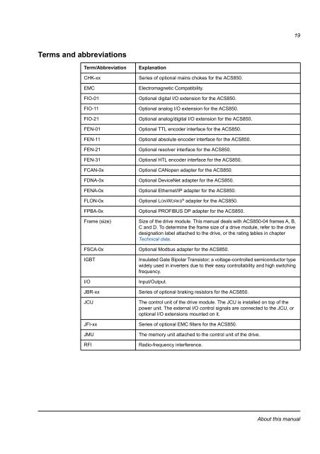
19Terms and abbreviationsTerm/AbbreviationCHK-xxEMCFIO-01FIO-11FIO-21F<strong>EN</strong>-01F<strong>EN</strong>-11F<strong>EN</strong>-21F<strong>EN</strong>-31FCAN-0xFDNA-0xF<strong>EN</strong>A-0xFLON-0xFPBA-0xExplanationSeries of optional mains chokes for the <strong>ACS850</strong>.Electromagnetic Compatibility.Optional digital I/O extension for the <strong>ACS850</strong>.Optional analog I/O extension for the <strong>ACS850</strong>.Optional analog/digital I/O extension for the <strong>ACS850</strong>.Optional TTL encoder interface for the <strong>ACS850</strong>.Optional absolute encoder interface for the <strong>ACS850</strong>.Optional resolver interface for the <strong>ACS850</strong>.Optional HTL encoder interface for the <strong>ACS850</strong>.Optional CANopen adapter for the <strong>ACS850</strong>.Optional DeviceNet adapter for the <strong>ACS850</strong>.Optional Ethernet/IP adapter for the <strong>ACS850</strong>.Optional LONWORKS ® adapter for the <strong>ACS850</strong>.Optional PROFIBUS DP adapter for the <strong>ACS850</strong>.Frame (size) Size of the drive module. This manual deals with <strong>ACS850</strong>-<strong>04</strong> frames A, B,C and D. To determine the frame size of a drive module, refer <strong>to</strong> the drivedesignation label attached <strong>to</strong> the drive, or the rating tables in chapterTechnical data.FSCA-0xIGBTI/OJBR-xxJCUJFI-xxJMURFIOptional Modbus adapter for the <strong>ACS850</strong>.Insulated Gate Bipolar Transis<strong>to</strong>r; a voltage-controlled semiconduc<strong>to</strong>r typewidely used in inverters due <strong>to</strong> their easy controllability and high switchingfrequency.Input/Output.Series of optional braking resis<strong>to</strong>rs for the <strong>ACS850</strong>.The control unit of the drive module. The JCU is installed on <strong>to</strong>p of thepower unit. The external I/O control signals are connected <strong>to</strong> the JCU, oroptional I/O extensions mounted on it.Series of optional EMC filters for the <strong>ACS850</strong>.The memory unit attached <strong>to</strong> the control unit of the drive.Radio-frequency interference.About this manual


