

EN / ACS850-04 (1.1 to 45 kW) Hardware Manual - VAE ProSys sro
EN / ACS850-04 (1.1 to 45 kW) Hardware Manual - VAE ProSys sro
EN / ACS850-04 (1.1 to 45 kW) Hardware Manual - VAE ProSys sro
- No tags were found...

Create successful ePaper yourself
Turn your PDF publications into a flip-book with our unique Google optimized e-Paper software.
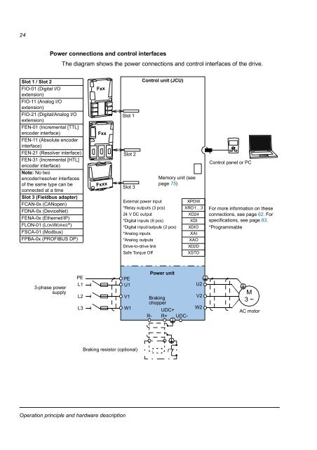
24Power connections and control interfacesThe diagram shows the power connections and control interfaces of the drive.Slot 1 / Slot 2FIO-01 (Digital I/Oextension)FIO-11 (Analog I/Oextension)FIO-21 (Digital/Analog I/Oextension)F<strong>EN</strong>-01 (Incremental [TTL]encoder interface)F<strong>EN</strong>-11 (Absolute encoderinterface)F<strong>EN</strong>-21 (Resolver interface)F<strong>EN</strong>-31 (Incremental [HTL]encoder interface)Note: No twoencoder/resolver interfacesof the same type can beconnected at a timeSlot 3 (Fieldbus adapter)FCAN-0x (CANopen)FDNA-0x (DeviceNet)F<strong>EN</strong>A-0x (Ethernet/IP)FLON-01 (LONWORKS ® )FSCA-01 (Modbus)FPBA-0x (PROFIBUS DP)FxxFxxFxxxSlot 1Slot 2Slot 3Control unit (JCU)Memory unit (seepage 75)External power inputXPOW*Relay outputs (3 pcs) XRO1…324 V DC output XD24*Digital inputs (6 pcs)XDI*Digital input/outputs (2 pcs) XDIO*Analog inputsXAI*Analog outputsXAODrive-<strong>to</strong>-drive linkXD2DSafe Torque OffXSTOControl panel or PCFor more information on theseconnections, see page 62. Forspecifications, see page 83.*Programmable3-phase powersupplyPEL1L2L3PEU1V1W1Power unitBrakingchopperR-UDC+R+ UDC-U2V2W2M3 ~AC mo<strong>to</strong>rBraking resis<strong>to</strong>r (optional)t°Operation principle and hardware description


