

EN / ACS850-04 (1.1 to 45 kW) Hardware Manual - VAE ProSys sro
EN / ACS850-04 (1.1 to 45 kW) Hardware Manual - VAE ProSys sro
EN / ACS850-04 (1.1 to 45 kW) Hardware Manual - VAE ProSys sro
- No tags were found...

You also want an ePaper? Increase the reach of your titles
YUMPU automatically turns print PDFs into web optimized ePapers that Google loves.
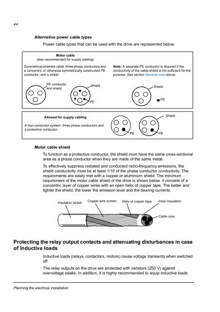
44Alternative power cable typesPower cable types that can be used with the drive are represented below.Mo<strong>to</strong>r cable(also recommended for supply cabling)Symmetrical shielded cable: three phase conduc<strong>to</strong>rs anda concentric or otherwise symmetrically constructed PEconduc<strong>to</strong>r, and a shieldNote: A separate PE conduc<strong>to</strong>r is required if theconductivity of the cable shield is not sufficient for thepurpose. See section General rules above.PE conduc<strong>to</strong>rand shieldShieldShieldPEPEAllowed for supply cablingShieldA four-conduc<strong>to</strong>r system: three phase conduc<strong>to</strong>rs anda protective conduc<strong>to</strong>r.PEPEMo<strong>to</strong>r cable shieldTo function as a protective conduc<strong>to</strong>r, the shield must have the same cross-sectionalarea as a phase conduc<strong>to</strong>r when they are made of the same metal.To effectively suppress radiated and conducted radio-frequency emissions, theshield conductivity must be at least 1/10 of the phase conduc<strong>to</strong>r conductivity. Therequirements are easily met with a copper or aluminium shield. The minimumrequirement of the mo<strong>to</strong>r cable shield of the drive is shown below. It consists of aconcentric layer of copper wires with an open helix of copper tape. The better andtighter the shield, the lower the emission level and the bearing currents.Insulation jacketCopper wire screenHelix of copper tapeInner insulationCable coreProtecting the relay output contacts and attenuating disturbances in caseof inductive loadsInductive loads (relays, contac<strong>to</strong>rs, mo<strong>to</strong>rs) cause voltage transients when switchedoff.The relay outputs on the drive are protected with varis<strong>to</strong>rs (250 V) agains<strong>to</strong>vervoltage peaks. In addition, it is highly recommended <strong>to</strong> equip inductive loadsPlanning the electrical installation


