5300 2H-2C User Manual.pdf - Braeburn Systems
5300 2H-2C User Manual.pdf - Braeburn Systems
5300 2H-2C User Manual.pdf - Braeburn Systems

You also want an ePaper? Increase the reach of your titles
YUMPU automatically turns print PDFs into web optimized ePapers that Google loves.
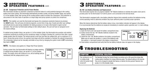
3 ADDITIONALOPERATION FEATURES cont.3.12 Compressor Protection and AC Power MonitorThis thermostat includes an automatic compressor protection feature to avoid potential damage to the coolingsystem from short cycling. This thermostat automatically provides a delay, set during Installer Setup, see section4.2 of the Installer Guide, after turning off the cooling system output to protect the compressor. This protection isalso present in the heat mode of operation on single stage heat pump systems to protect the compressor.NOTE: The installer can reset the thermostat and bypass the compressor protection features by pressingthe RESET button. This will erase all entered programs, current time of day, day of week and other user settingsand should only be used during installation for testing purposes or to reset a thermostat to regain normaloperation. This will return all thermostat settings to their default values. The user will have to reprogram all ofthe erased settings.If enabled during Installer Setup, see section 4.2 of the Installer Guide, this thermostat also provides cold weathercompressor protection by locking out the compressor stage (1st Stage) of heating for a period of time after a poweroutage greater than 60 minutes. The lockout period is one hour less than the outage time, up to a maximum of 12hours. During that period of time, the auxiliary heat stage will still be available to maintain the setpoint temperature.The compressor lockout can be manually overridden at any time by changing the system mode to OFF momentarily,then back to HEAT.3 ADDITIONALOPERATION FEATURES cont.3.13 Low Battery Detection and ReplacementThis thermostat requires two (2) properly installed “AA” Alkaline batteries to maintain the system clock and toprovide power for the thermostat if 24 volt AC power is not connected to the terminal block.This thermostat is equipped with a low battery detection feature that constantly monitors the batteries duringnormal operating mode to determine whether they have sufficient power to provide proper operation.When this feature determines that the battery status is low, a low battery indicator will appear in the display.It is recommended that the batteries be replaced immediately to maintain system operation and / or clock settings.Replacing the Batteries1. Open the front cover and locate the battery compartment door. SYSTEM MO2. Gently remove the two “AA” Alkaline batteries located in theMORN AMbattery compartment.COOL3. Install two new “AA” Alkaline batteries into battery compartment.Make sure to match the positive (+) ends of the batteries withthe positive (+) terminals located in the battery compartment.4. Close battery compartment and verify that the low battery indicator does not appear in the display.FANAUTONOTE: This feature only applies to 2 Stage Heat Pump <strong>Systems</strong>.During a power loss, the thermostat will display an outage warning,if enabled during Installer Setup, see section 4.2 of the InstallerGuide. The system clock will continue to run, and all settings will bemaintained until the outage period is over.SYSTEM MODAYHEATFANAUTO4 TROUBLESHOOTINGSYMPTOMFan continues to runin cooling modewhen the system hasturned off.POTENTIAL SOLUTIONThe Residual Cooling Fan Control Feature can allow up to a 90 second fan delay aftercooling system shutdown for energy efficiency gains. The default setting is 60 seconds.This can be changed to disable this feature or shorten the time period if desired. Seesection 4.2 of the Installer Guide.20 21