Controlled Current-Mode Multifunction Filters - Telfor 2008
Controlled Current-Mode Multifunction Filters - Telfor 2008
Controlled Current-Mode Multifunction Filters - Telfor 2008

You also want an ePaper? Increase the reach of your titles
YUMPU automatically turns print PDFs into web optimized ePapers that Google loves.
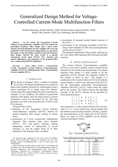
PCA ii 21n + _ i 3v 1vv 23V G ≙ nFig. 2. Schematic symbol of PCA.On the basis of the research results in pure currentmodecircuits in the Brno University of Technology thenew active element PCA (Programmable <strong>Current</strong>Amplifier) [12] has been defined. <strong>Current</strong>ly, incooperation with ON Semiconductor we work on themicroelectronic structure realization of this element. Theschematic symbol of the PCA element is shown in Fig. 2.Relations between the individual terminals of the PCAelement can be described by hybrid matrix as follows:⎡v1⎤ ⎡ 0 0 0⎤⎡i1⎤⎢ ⎥ ⎢20 0⎥ ⎢ ⎥⎢i⎥=⎢n⎥⋅⎢v2⎥, (2)⎢⎣i ⎥ ⎢3⎦ ⎣−n 0 0⎥⎦⎢⎣v⎥3⎦where i 1 is the input current, i 2 and i 3 are output currents ofthe element and parameter n is the current mu-factor,whose value could be from +/–1 to cca. +/–50 (limited byreason of the realization in integrated form).III. FILTER DESIGNAn autonomous circuit is a circuit that does not haveexcitation sources and it does not have a defined inputterminal either. Such a circuit has the so-calledcharacteristic equation in the form of a sum of theproducts of admittances Y x , from which we already canread a possible application of this circuit, namely either asan oscillator or as various types of frequency filter.Fig. 3. Initial general autonomous circuit.Fig. 4. Designed current-mode frequency filter.In the implementation of filters, emphasis is placed ontheir maximum simplicity. Advantageous filters are those,which have a maximum of grounded passive elementswith a view to easy integration of circuits or easy electricaltunability. In this case for tunability we have used theproperties of the PCA active elements. The designedautonomous circuit shown in Fig. 3 corresponds to theserequirements. On presented autonomous circuit the wholedesign procedure of frequency filter design is shown. Thecharacteristic equation of this circuit obtained using theSNAP software [13] is:D = YY1 2Y3+ nn2 3α 2α3Y1gm2gm3+ nn1 3αα 1 2α3gm1gm2gm3= 0.(3)In the filter design we have restricted only to CFTA+/–[14] element. Due to choosing the passive elementsY 1 = sC 1 , Y 2 = G 2 , and Y 3 = sC 3 equation (3) changes to aform which satisfies the feasibility conditions of thefrequency filter:2D = s CCG1 3 2+ nn2 3s Cg1 m2gm3 + nn1 3gm1gm2gm3= 0, (4)where s = jωis the complex variable. The designedfrequency filter of the type SIMO (single-input-multioutput)working in current mode is shown in Fig. 4. Thecomplex current transfer functions of the designed filterwith driving current I IN have the form:OUT1 1 3 m1 m2 m3LP : I =− nng g g , (5)IDINI s 2OUT2 1 3 m2HP : =− CC gIIND, (6)OUT3 1 2 m2BP1: = g ,IIND(7)OUT4 1 3 1 m2 m3BP2 : nn Cg g= ,IIND(8)OUT5 2 3 1 m2 m3BP3 : nn Cg g=− ,ID(9)IN2OUT1+OUT2CC1 3gm2 + nn1 3gm1gm2 gm3BS :I I =− sIIND. (10)The circuit designed according to Fig. 4 ismultifunction, i.e. it allows a second-order low-pass filter(LP), band-pass filter (BP1, BP2, and BP3), and high-passfilter (HP) and band-stop filter (BS) to be implemented.According to (4), the characteristic frequency ω 0 , thequality factor Q and the ω 0 /Q of these filters are:gm1gm2gm3ω0= nn1 3CCG , (11)11 3 2nCG g1 3 2 m1Q =, (12)n2 n3 C1 gm2 gm3ω0nng2 3 m2g=m3. (13)Q C3G2From the equations (11) and (12) it is evident that thecharacteristic frequency ω 0 can be tuned using current mufactorsn 1 = n 3 = n independently and the quality factor Qcan be controlled using current mu-factor n 2 independentlyof other parameters of the frequency filter.401
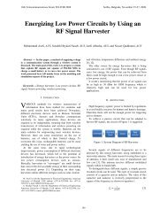
IV. SENSITIVITY ANALYSISThe relative sensitivities [4] of the characteristicfrequency ω 0 (11), the quality factor Q (12) and the ω 0 /Q(13) for the constituent active and passive elements are:ω0 ω 10 01, 3 , m1, m2 , m3 1, 3 , 2,ωSn n g g g=− SC C G= Sn=20, (14)21S =− S = , S =− 1, (15)Q Q Qn1, C3, G2, gm1 n3, C1, gm2,gm3 2n2ω0 Q ω0 Q ω0Qn2, n3, gm2 , gm3 C 3 ,G2 n1, C1 , gm1S =− S = 1, S = 0. (16)From these results it is evident that the sensitivities arelow, which is an advantage of this structure.(a)V. SIMULATION RESULTSThe characteristics of the designed multifunction filterstructure have been verified using PSPICE simulations.Schematic symbol, block diagram and the used internalstructure of the CFTA+/– element is shown in Fig. 5.Block diagram of the PCA element is shown in Fig. 6 (a).<strong>Current</strong> multiplier EL2082 [15] and the second-generationcurrent conveyor CCII+/– bipolar structure [16] has beenused for the simulation of PCA element, which is shownin Fig. 6 (b). In the design the transistor model parametersNR100N (NPN) and PR100N (PNP) of bipolar arraysALA400 from AT&T [17] were used. Bias currentsI B = I B1 = 400 μA have been chosen. The transconductanceg m of CFTA+/– elements can be set by current I B2 = g m /20.The simulated frequency characteristics of the circuit inFig. 4 are shown in Fig. 7. For the current mu-factorsn 1 = n 2 = n 3 = 1.012, for the characteristic frequencyf 0 ≈ 300 kHz and for the quality factor of filters Q = 1 thefollowing values have been chosen: C 1 = C 3 = 450 pF,G 2 = 1 mS (R 2 = 1 kΩ) and g m1 = g m2 = g m3 = 1 mS(I B21 = I B22 = I B23 = 50 μA). From the simulation results itis evident that the final solution corresponds to theoreticalexpectations. The possibility of tuning the characteristicfrequency of band-pass filter (9) is shown in Fig. 8. Forthe current mu-factor n = {0.126;0.331;1.012;3.598}according to (11) the characteristic frequency has thevalues as follows: f 0 = {30;100;300;1 000}kHz, where(ω 0 = 2πf 0 ).(b)Fig. 6. (a) Block diagram of PCA element, (b) realizationof the PCA using current multiplier EL2082 andsecond-generation current conveyor CCII+/–.Gain (dB)0-20-40-60LPBP3HPBS10k 100k 1M 10MFrequency (Hz)Fig. 7. Simulation results of current-mode multifunctionfilter in Fig. 4.0(a)(b)Gain (dB)-20-40(c)Fig. 5. (a) Schematic symbol, (b) block diagram and(c) used bipolar implementation of CFTA+/– element.n = 0.126n = 0.331n = 1.012n = 3.598-6010k 100k 1M 10MFrequency (Hz)Fig. 8. Simulation results of tunable current-mode bandpassfilter BP3 shown in Fig. 4.402
Gain (dB)0-20-40n2 = 0.025n2 = 0.102n2 = 0.334n2 = 1.415n2 = 6.667-6010k 100k 1M 10MFrequency (Hz)Fig. 9. Simulation results of controlling the quality factorQ for current-mode band-pass filter BP3 shown in Fig. 4.Frequency (MHz)1010.10.01idealsimulationFrequency = f (n)Q = f (n2)0.01 0.1 1 10n, n 2 (-)Fig. 10. Simulation results evaluationaccording to Fig. 8 and Fig. 9.The possibility of controlling the quality factor Q of thecurrent-mode band-pass filter BP3 for the characteristicfrequency f 0 ≈ 300 kHz using current mu-factor n 2 isshown in Fig. 9. For n 2 = {0.025;0.102;0.334;1.415;6.667} according to (12) the quality factor has the valuesas follows: Q = {0.15;0.707;3;10;40}. These simulationsshow that the designed multifunction filter with low valueof current mu-factor n the characteristic frequency can betuned over two decades with high quality factor Q.The simulation results according to Fig. 8 and Fig. 9 areshown in Fig. 10. The possibility of tuning thecharacteristic frequency by current mu-factor n andcontrolling the quality factor by current mu-factor n 2 ofthe proposed filter is shown in Fig. 10. The gain error ofthe current mu-factor of the current multiplier EL2082element is for V G = 2 V about –3.8 % [15], which isevident from these simulations also. From thesesimulations it is also evident that, the most exact resultsare for current mu-factors n ≈ n 2 ≈ 1.VI. CONCLUSIONThe paper presents generalized element GCFTA and anovel active element PCA. These active elements can beused for generalized design of tunable current-modeanalogue filters. The possible internal bipolar structure ofCFTA+/– element and the realization of the PCA usingcurrent multiplier EL2082 and second-generation current1001010.1Q (-)conveyor CCII+/– are given. The presented current-modefrequency filter has been designed using generalizedfrequency filter design method and it allows mutuallyindependent change of characteristic frequency ω 0 andquality factor Q. The tuning of characteristic frequency ω 0can be easily enabled using current mu-factors of the1 PCA and 3 PCA elements (by parameter n) and the controlof the quality factor Q for current-mode band-pass can beprovided using current mu-factor of the 2 PCA element (byparameter n 2 ). In the structure, all passive elements aregrounded which is advantageous because of the easyrealization of grounded passive elements in integration.All current responses are taken directly from highimpedanceoutputs of the active elements. The filterenables realizing simultaneously LP, BP and HP filterresponses. The band-stop filter can be realized by asuitable connection of current outputs. The sensitivities ofthe filter to the active and passive elements are low.REFERENCES[1] G. W. Robetrs, A. S. Sedra, “All <strong>Current</strong>-mode Frequency Selective<strong>Filters</strong>”, Electronics Lettres, vol. 25, no. 12, pp. 759–760, 1989.[2] O. Cicekoglu, A. Toker, H. Kuntman, “Universal immittancefunction simulators using current conveyors”, Computers andElectrical Engineering, vol. 27, pp. 227–238, 2001.[3] Y. S. Hwang, S. I. Liu, D. S. Wu, Y. P. Wu, “Table-based lineartransformation filters using OTA-C techniques”, ElectronicsLetters, vol. 30, no. 24, 1994.[4] W. K. Chen, The Circuits and <strong>Filters</strong> Handbook. New York, CRCPress, 2003.[5] J. Koton, K. Vrba, “Method for designing frequency filters usingUniversal <strong>Current</strong> Conveyors”, Int. Trans. on Comp. Science andEng., vol. 13, no. 1, pp. 144–154, 2005.[6] N. Herencsár, K. Vrba, “Generalized Design of <strong>Current</strong>-<strong>Mode</strong><strong>Filters</strong> using BOTAs”, J. of Active and Passive Electronic Devices,to be published.[7] J. J. Chen, C. C. Chen, H. W. Tsao, and S. I. Liu, “<strong>Current</strong>-modeoscillators using single current follower,” Electronics Letters,vol. 27, no. 22, pp. 2056-2059, 1991.[8] S. I. Liu, J. J. Chen, H. W. Tsao, J. H. Tsay, “Design of biquadfilters with a single current follower”, IEE Proc.-G, vol. 140, no. 3,pp. 165–170, 1993.[9] Y. Sun and J. K. Fidler, “Structure generation of current-mode twointegratorloop dual output-OTA grounded capacitor filters,” IEEETrans. Circuits Syst. II, vol. 43, no. 9, pp. 659–663, 1996.[10] S. A. Mahmoud, A. M. Soliman, “A CMOS programmablebalanced output transconductor for analogue signal processing”, Int.J. of Electronics, vol. 82, no. 6, pp. 605–620, 1997.[11] J. Wu, E. I. El-Masry, “Universal voltage- and current-mode OTAsbased biquads”, Int. J. of Electronics, vol. 85, no. 5, pp. 553–560,1998.[12] J. Koton, K. Vrba, P. A. Ushakov, J. Mišurec, “DesigningElectronically Tunable Frequency <strong>Filters</strong> Using the Signal FlowGraph Theory”, in Proc. of the 31th Int. Conference onTelecommunications and Signal Processing – TSP <strong>2008</strong>,Parádfürdő, Hungary. pp. 1–4, <strong>2008</strong>.[13] Z. Kolka, “SNAP – Program for Symbolic Analysis,”Radioengineering, vol. 8, no. 1, pp. 23–24, 1999.[14] N. Herencsár, J. Koton, I. Lattenberg, K. Vrba, “Signal-FlowGraphs for <strong>Current</strong>-<strong>Mode</strong> Universal Filter Design Using <strong>Current</strong>Follower Transconductance Amplifiers (CFTAs)”, in Proc. of theInt. Conference Applied Electronics – APPEL <strong>2008</strong>, Pilsen, CzechRep., pp. 113–116, <strong>2008</strong>.[15] Datasheet EL2082: http://www.intersil.com/data/fn/fn7152.pdf.[16] A. Fabre, O. Saaid, F. Wiest, C. Boucheron, “<strong>Current</strong> controlledbandpass filter based on translinear conveyors”, Electronics Letters,vol. 31, no. 20, pp. 1727–1728, 1995.[17] D. R. Frey, “Log-domain filtering: an approach to current-modefiltering,” IEE Proc.-G, vol. 140, pp. 406–416, 1993.403