LM8000 Operation/Installation Manual - Balboa Direct
LM8000 Operation/Installation Manual - Balboa Direct
LM8000 Operation/Installation Manual - Balboa Direct
You also want an ePaper? Increase the reach of your titles
YUMPU automatically turns print PDFs into web optimized ePapers that Google loves.
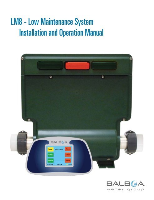
LM8 - Low Maintenance System<strong>Installation</strong> and <strong>Operation</strong> <strong>Manual</strong>1
Important NoticesINTELLECTUAL PROPERTY ADVISEMENTAll Intellectual property, as defined below, owned by orwhich is otherwise the property of <strong>Balboa</strong> Water Group orits respective suppliers relating to the <strong>Balboa</strong> Water GroupLM8 Low Maintenance System, including but not limitedto, accessories, parts, or software relating there to (the“LM8 - Low Maintenance System”), is proprietary to <strong>Balboa</strong>Water Group and protected under federal laws, state laws,and international treaty provisions. Intellectual Propertyincludes, but is not limited to, inventions (patentable orunpatentable), patents, trade secrets, copyrights, software,computer programs, and related documentation, and otherworks of authorship. You may not infringe or otherwise violatethe rights secured by the Intellectual Property. Moreover,you agree that you will not (and will not attempt to) modify,prepare derivative works of, reverse engineer, decompile,disassemble, or otherwise attempt to create source codefrom the software. No title to or ownership in the IntellectualProperty is transferred to you. All applicable rights of theIntellectual Property shall remain with <strong>Balboa</strong> Water Groupand its suppliers.END USER WARNINGThis <strong>Installation</strong> <strong>Manual</strong> is provided solely to aid qualified spaservice technicians in installing spas with control systemsmanufactured by <strong>Balboa</strong> Water Group. <strong>Balboa</strong> controls haveabsolutely no end user serviceable parts. <strong>Balboa</strong> Water Groupdoes not authorize attempts by the spa owner/user to repair orservice any <strong>Balboa</strong> products. Non-qualified users should neveropen or remove covers, as this will expose dangerous voltagepoints and other dangerous risks. Please contact your dealer orauthorized repair center for service.GFCI COMPLIANCE It is required by code to install a Ground Fault CircuitInterrupter (GFCI) in the supply power for a spa. Thisdevice will trip the breaker if there is an unsafe electricalcondition caused by a malfunctioning component or eventhe slightest short to ground. Note: Connect the control system only to a circuitprotected by a Class A GFCI mounted at least 5’ (1.52M)from the inside walls of the spa/hot tub and in line of sightfrom the equipment compartment. Refer to NEC (National Electrical Code), 2005 Edition,Article 680 for more information.2WARNINGS: DANGER! RISK OF ELECTRIC SHOCK! All electrical work must be performed by a qualifiedelectrician and must conform to all national, state, andlocal codes. Before making any electrical connections, make certainthat the Main Power breaker from the house breaker boxhas been turned off. Do not attempt service of this control system. Contactyour dealer or service organization for assistance. Do not permit any electric appliance, such as a light,telephone, radio, or television within 5’ (1.5m) of a poolor spa. Follow all owner’s manual power connectioninstructions. <strong>Installation</strong> must be performed by a licensed electricianand all grounding connections must be properlyinstalled. No user serviceable parts. Water temperature in excess of 38˚C may be injurious toyour health. Disconnect the electrical power before servicing. Keep access door closed.CAUTIONTest the ground fault circuit interrupter before each useof the spa.Read the instruction manual.Adequate drainage must be provided if the equipment is tobe installed in a pit.To ensure continued protection against shock hazard,use only identical replacement parts when servicing.WARNING Water temperature in excess of 38˚C may be injurious toyour health. Disconnect the electrical power before servicing. Keep the pack enclosure closed unless being serviced bya qualified serviced technician.©2011 <strong>Balboa</strong> Water Group. All rights reserved.
Table of ContentsImportant Notices . . . . . . . . . . . . . . . . . . . . . . . . . . . . . . . . . . . . . . . . . . . . 2Intellectual Property Advisement . . . . . . . . . . . . . . . . . . . . . . . . . . . . . . . . . . . . 2End User Warning . . . . . . . . . . . . . . . . . . . . . . . . . . . . . . . . . . . . . . . . . . 2GFCI compliance . . . . . . . . . . . . . . . . . . . . . . . . . . . . . . . . . . . . . . . . . . . 2Warnings: Danger! Risk of Electric Shock! . . . . . . . . . . . . . . . . . . . . . . . . . . . . . . . 2Introduction to the LM8 System . . . . . . . . . . . . . . . . . . . . . . . . . . . . . . . . . . . . . . 4Overview . . . . . . . . . . . . . . . . . . . . . . . . . . . . . . . . . . . . . . . . . . . . . . . . 5Automatic Functions . . . . . . . . . . . . . . . . . . . . . . . . . . . . . . . . . . . . . . . . . 5Initial <strong>Installation</strong> . . . . . . . . . . . . . . . . . . . . . . . . . . . . . . . . . . . . . . . . . . . 5Preferences . . . . . . . . . . . . . . . . . . . . . . . . . . . . . . . . . . . . . . . . . . . . . 5Test . . . . . . . . . . . . . . . . . . . . . . . . . . . . . . . . . . . . . . . . . . . . . . . . 5<strong>Operation</strong> . . . . . . . . . . . . . . . . . . . . . . . . . . . . . . . . . . . . . . . . . . . . . . 6Home Screen . . . . . . . . . . . . . . . . . . . . . . . . . . . . . . . . . . . . . . . . . . . . 6Setup Screen . . . . . . . . . . . . . . . . . . . . . . . . . . . . . . . . . . . . . . . . . . . . 6LM8 Modules . . . . . . . . . . . . . . . . . . . . . . . . . . . . . . . . . . . . . . . . . . . . . . 7Control Modules . . . . . . . . . . . . . . . . . . . . . . . . . . . . . . . . . . . . . . . . . . . 7Configuration and <strong>Operation</strong> . . . . . . . . . . . . . . . . . . . . . . . . . . . . . . . . . . . . . . . . 8Configuration - Filter Source & Breaker . . . . . . . . . . . . . . . . . . . . . . . . . . . . . . . . . 8Wiring <strong>Installation</strong> . . . . . . . . . . . . . . . . . . . . . . . . . . . . . . . . . . . . . . . . . . 9Startup Procedure . . . . . . . . . . . . . . . . . . . . . . . . . . . . . . . . . . . . . . . . . . 9Pump and Blower Settings . . . . . . . . . . . . . . . . . . . . . . . . . . . . . . . . . . . . . .10Setting the Time . . . . . . . . . . . . . . . . . . . . . . . . . . . . . . . . . . . . . . . . . . .10Temperature Selection . . . . . . . . . . . . . . . . . . . . . . . . . . . . . . . . . . . . . . . .11Filtration Settings . . . . . . . . . . . . . . . . . . . . . . . . . . . . . . . . . . . . . . . . . .12Status Screen . . . . . . . . . . . . . . . . . . . . . . . . . . . . . . . . . . . . . . . . . . . .13Locking the Display Screen . . . . . . . . . . . . . . . . . . . . . . . . . . . . . . . . . . . . . .13Mode . . . . . . . . . . . . . . . . . . . . . . . . . . . . . . . . . . . . . . . . . . . . . . . .14Pumps . . . . . . . . . . . . . . . . . . . . . . . . . . . . . . . . . . . . . . . . . . . . . . . .14My Spa . . . . . . . . . . . . . . . . . . . . . . . . . . . . . . . . . . . . . . . . . . . . . . .15Screensaver . . . . . . . . . . . . . . . . . . . . . . . . . . . . . . . . . . . . . . . . . . . . .16Panel Messages -- Error & Info Messages . . . . . . . . . . . . . . . . . . . . . . . . . . . . . . . .16Accessories and Optional Modules . . . . . . . . . . . . . . . . . . . . . . . . . . . . . . . . . . . .17Audio . . . . . . . . . . . . . . . . . . . . . . . . . . . . . . . . . . . . . . . . . . . . . . . .17LED Lighting . . . . . . . . . . . . . . . . . . . . . . . . . . . . . . . . . . . . . . . . . . . . .18GFCI Wiring <strong>Installation</strong> Diagram . . . . . . . . . . . . . . . . . . . . . . . . . . . . . . . . . . . . .19<strong>Balboa</strong> Domestic Wiring Configuration - Board No. 57129 . . . . . . . . . . . . . . . . . . . . . . . . .20120V & 240V Wiring with Heater Options . . . . . . . . . . . . . . . . . . . . . . . . . . . . . . . . . .21Specifications . . . . . . . . . . . . . . . . . . . . . . . . . . . . . . . . . . . . . . . . . . . . . .22Troubleshooting . . . . . . . . . . . . . . . . . . . . . . . . . . . . . . . . . . . . . . . . . . . . .23Index . . . . . . . . . . . . . . . . . . . . . . . . . . . . . . . . . . . . . . . . . . . . . . . . . .263
OverviewAUTOMATIC FUNCTIONS1. The most important function of the spa control is tosafely manage the heater. Normally the heater is turnedon whenever the filter pump is running and the watertemperature is 1 degree less than the set temperature.Once on, the heater will stay on until the watertemperature is 1 degree more than the set temperature.2. The heater will be forced to stay off if there is not anadequate flow of water through the heater. This isdetermined by performing a flow test prior to each heateractivation. If the flow of water is too low to cool theheater 2 degrees in less than a minute, following a 6second heater test, the heater will not be allowed on andthe statues screen will appear showing a flow rate lessthan 6 gal./min.3. The heater will also be forced off if too many motors arerunning for the size of the circuit breaker.4. Anytime the water in the spa is 112F or more, all pumpsare shut down. The pumps can be used again only whenthe water temperature has dropped to 104F.5. If the water passing through the heater is 118F, or more,the temperature display is locked on the display and theheater and all pumps are held off until a manual reset(circuit breaker) is accomplished. The blower will be turnedon to assist in cooling of the water.6. Anytime the heater element (while off) falls to atemperature of 48F, it is presumed that the spa’s plumbingmay be in danger of freezing. All pumps and the blowerare turned on for 1 minute. If the heater element sensor isstill 48F or less after 1 minute, the blower and pumps areturned off and the heater is turned on to raise the waterto 60F. If for some reason (flow) the heater can’t be turnedon, the pumps will continue to run until the temperature ofthe water reaches 49F.7. Once a day, at 10 am, any pump or blower that hasn’t beenrunning in the last 24 hours is turned on for 15 seconds topurge stale water.8. All components are automatically timed out, as follows:Pumps – 30 minutesBlower – 30 minutesLEDs – 4 hoursAudio – 1.5 HoursINITIAL INSTALLATION1. Verify that circuit breaker is in off position.2. Remove lower pack cover.3. Connect 120VAC or 240VAC to pack, per wiring diagram.4. Connect all motors, ozonator, touchscreen spaside, LEDs,speakers, and antenna, per legends on relay board.5. Turn circuit breaker back on.6. Observe transformer LED. If LED is green, power isconnected and the transformer is working.7. Return circuit breaker to off position.8. Replace pack cover.PREFERENCES1.2.Close the circuit breaker again.Use the setup button to set time, temperature, filterhours, mode, circuit breaker size, my spa information,pump configuration, or to lock the spaside buttons. Theindividual displays are self-explanatory.TEST1. Turn the circuit breaker off and back on to start theautomatic self-test sequence.2. Observe the spaside buttons as each spa component istested. The button associated with each component willchange from yellow to green; proper operation is verified.If a button turns white, the associated component isdefective and must be replaced.3. Observe the display for messages which may indicateother failed components, such as:F1 (Fuse 1)F2 (Fuse 2)F3 (Fuse 3)Bad sensorRel (Relay board)COMM (Communications problem)4. As soon as all buttons are yellow or green, and thereare no error messages on the display, the spa is ready tooperate without concern.5
Overview (cont.)OPERATIONTurn on Jet1, Jet2, and the blower by pressing the appropriatebutton. Note that Jet1 and Jet2 will activate a low speedwinding with the first press of the button and a high speedwinding with the second press.Observe that as each component is successfully activated,the associated button will turn green. If, however, a certaincomponent appears to be inoperative, a quick series ofautomatic tests will be performed to isolate the failure tothat component or some other problem area, like a blownfuse. If the tests determine that the component is actuallyfailed, the button will turn white, indicating the likely need forreplacement of that component.Turn on the LED lighting by pressing the LEDs button. Note thateach time the LEDs are turned on, the display will show thecurrent color program, which can be changed as desired. Thelast selection is a music reflections program that follows thebeat of the music. If selected, the brightness can be changedwith the up and down buttons.Turn on the audio by pressing the audio button. Follow thedisplay messages to adjust volume, bass, music source, andFM tuning.HOME SCREENThe main screen is the “home” screen: Use the “pump 1”, “pump 2”, or “blower” buttons toactivate the desired component.a) If the button is red, it means the component is off.b) If the button is yellow, it means the low speed isactivated.c) If the button is green, the high speed is activated.d) The blower is simply green when it is on, and red whenit is off.e) If the button turns white, that means there is some sortof a problem associated with that component (lowcurrent, blown fuse, disconnected, etc.) If a profile is selected, the name of the profile will bedisplayed below the “welcome” banner. In the lower left-hand corner, the current time is displayed. In the lower right-hand corner, the current watertemperature is displayed. A “sun” icon is displayed directly to the left of the watertemperature whenever the heater is energized. Note: If the spa does not have a blower, a “ My Spa”button will be shown. Selecting “My Spa” acts the sameas selecting “My Spa” from the “Setup” screen. “My Spa”is described in detail below. From any other screen, the “Back” button will take youto the previous screen. On any screen that has a “help”button present, it will take you to a brief description of thescreen’s purpose and use.SETUP SCREENTo set the temperature, time, filter hours, filter mode, userprofiles, or physical configuration of the spa, select “Setup”on the “Home” screen. More detailed explanations are withinthe text.6
LM8 ModulesCONTROL MODULESThe Red Control Module manages all Logic Functions:1. Keeps time of day2. Reports water temperature3. Saves settings in flash memory4. Translates messages from Touchscreen and activates Relay Board5. Times out Pumps, Lights, and Audio6. Safely maintains Heater Function7. Monitors Sensor Health8. Backup Processor also watches for Heater or Sensor problemsNOTE ON CHANGING COMPONENTSWhen changing modules or panels, be sure thatthe system is powered down completely beforeremoving or inserting any modules or panelsinto the system. If the system is still powered upwhile removing or inserting any module or panel,irreparable damage may occur to the module, themother board, or the panel.The Yellow / Green LED Module provides colors and intensity selectedat Topside.The Green Audio Module tunes FM from Topside Commands anddelivers 100W of Music.Blank green modules are placeholders. However, these modules canbe replaced by different colored modules for LED functions or stereo.12 VAC ModuleYellow / Dark GreenPart No. 5711812 VDC LED Sloan ModuleYellow / Lime GreenPart No. 57119<strong>Balboa</strong> Control ModuleRed / RedPart No. 57130Blank ModuleDark Green / Dark GreenPart No. 35006-GAudio ModuleLime Green / Lime GreenPart No. 571167
Configuration and <strong>Operation</strong>CONFIGURATION - FILTER SOURCE & BREAKERThe LM8 spa pack contains a set-up to accommodate several sizesof household breakers. It will also regulate which components onthe spa can come on together to stay within the breaker settingrange. The heater is turned off whenever the current rules arerequired for any particular breaker setting.FILTER SOURCE (INSTALLATION)Home > Setup > Configuration > [Filter Source]During setup, the Configuration screen also allows the installerto choose the type of filter pump that will be used. If a circpump is selected, the pump will run continuously.Pump 1WELCOMETempSetting the Filter Source will affect how filtration timesare set. Also, the Pump 1 button on the Home screen will actdifferently than if a two speed Pump 1 were used.Pump 2Blower12:00PM HOME 100FSelectHome ScreenTemperatureTimeFilter HoursLock SpaModeConfigurationSetupStatusHelpBackBREAKER SETTING (INSTALLATION)Home > Setup > Configuration > [Breaker]From the Home screen, use the Up and Down Arrows to scrollthrough menus. 60A is the factory default. Press the Select button to choose the desired setting. Press the Save button to save any breaker settingchanges. Press the Back button to go back to the Home Screen.Note: Consider using the 60A breaker setting, and then wire thespa accordingly.12:00PM SETUP 100FSetup ScreenSelectFILTER SOURCECirc pumpLow Speed 1BREAKER30 Amps60 AmpsHelpBack12:00PM CONFIG 100FConfig Screen8
WIRING INSTALLATION1. The LM8 Spa requires a dedicated 50A circuit with a GFCI.The service cable must be 4-wire, 6 AWG.2. Turn off the circuit breaker before proceeding.3. Remove the lower lid after removing the 4 lid screws.4. Connect one 220v service wire ( usually black) to L1, theneutral wire (usually white) to neutral, and the other 220vservice wire (usually red) to L2. If there is any doubt,verify lines with a voltmeter.5. The green wire (safety ground) is brought into the enclosurewith the other wires, but it must then be routed back throughthe hole provided in the enclosure and connected securely tothe grounding bar.6. Verify that the transformer connectors are plugged in andeverything else is in place inside the pack, then turn on thecircuit breaker and verify that the green LED (D22) on the topedge of the board is on. (This verifies the power connections.)Turn the breaker back off and replace the lower pack lid.7. Turn on the circuit breaker. Observe that a self-test procedurewill immediately verify the condition of all motors, heaters,sensors, and all modules. If any button on the topside iswhite, it means that component is defective or unplugged.Other possible issues will result in a pop-up status screen,which can be analyzed to determine any other problems.Do not press any buttons on the topside control while thesystem is in self-test mode. This test usually takes only afew seconds.8. Be aware that each time before the heater is allowed tooperate, the pump and heater will be turned on and off toverify that the spa has flowing water. This process maytake up to 2 minutes. During this time, the pump cannot beoperated manually.9. If a “COMM ERROR” is seen, power down, then recheck theseating of the red module and the topside panel connector.Note: LM8 wiring diagrams are towards the back of this manual.STARTUP PROCEDURE1. Go to the topside control panel and look at the display.The spa will go through a startup self-test sequence and aflow test, which together will last for a couple of minutes.During this time, refrain from pushing any buttons on thetouch screen. During this period the temperature will bedisplayed as “0” and the time will be 12:00pm. Once theself-test is complete, the current water temperature willbe displayed and heating will begin based on the defaultset point of 100F (38C).Note: Pump 1 will be running at low speed continuouslyuntil the filter time and/or the time is set.Caution: If any errors appear during the start up period,refer to the troubleshooting section of the manual.2.You should hear the 2-speed pump turn on at low speed,see water moving through the jets, and see the Pump 1button illuminated yellow on the control panel. Press thePump 1 button again. You should hear the 2-speed pumpturn on high speed, and see the Pump 1 button illuminatedgreen.3. If the water is running smoothly through the lines, openthe seat(s) manifold air control valve and you should seean increase in jet pressure. Check and adjust the waterand airflow of every jet if necessary.4. Press the Pump 1 button a third time to turn off the2-speed pump.Note: This pump remains on if filtration or heat is neededon spas without a circ pump.5. For a two pump spa, press the Pump 2 button. You shouldhear the pump turn on and see water flowing through thejets. Also, the Pump 2 button will illuminate green. Pressthe Pump 2 button again to turn off the pump.6. For the blower (if applicable), press the Blower button. Youshould hear the blower turn on and see bubbles in the jets.Also, the Blower button will illuminate green. Press theBlower button again to turn off the blower.9
PUMP AND BLOWER SETTINGSThe pump and blower settings on the spa can be adjusted onthe home menu screen by pressing either “PUMP 1”, “PUMP2”, or the “BLOWER” button, depending on which you desireto be adjusted. (Certain buttons will not show dependingon spa model.)SETTING THE TIMETo set the local time on your spa, select “SETUP” from thehome menu screen to access the setup menu screen.Home > Setup > TimePump 1WELCOMETempPump 1WELCOMETempPump 2SetupPump 2SetupBlowerStatusBlowerStatus12:00PM HOME 100FHome Screen12:00PMSETUPHome Screen100FThe settings for Pump 1 are: LOW, HIGH, and OFF. To adjustthe settings, select the “PUMP 1” button. For LOW, press thebutton once. For HIGH, press the button a second time. ForOFF, press the button a third time. During the LOW setting, thebutton will glow yellow. During the HIGH setting, the buttonwill glow green. When the pump is OFF, the button will glowred. If there is an issue with the pump, the button will glowwhite. (Please refer to troubleshooting.)SelectTemperatureTimeFilter HoursLock SpaModeConfigurationHelpBack12:00PM SETUP 0FSetup - TimeNote: If the system is in a period of filtration, the pump willrun at LOW speed and will not be able to be changed untilfiltration is complete.Select12:24 PM12/24HelpThe settings for Pump 2 are: ON and OFF. To turn pump 2 on oroff, select the “PUMP 2” button. For ON, the button will glowgreen. For OFF, the button will glow red. If there is a problemwith the pump, the button will glow white. (Please referto troubleshooting.)The settings for the Blower are: ON and OFF. To turn theblower on or off, select the “BLOWER” button. For ON, thebutton will glow green. For OFF, the button will glow red.12:00PMTIMETime Selection ScreenBack100FTo set the hour and minutes, use the Up and Down buttons as thenumerals flash. To toggle and select your preference, use Select. Tochoose either standard time or military time, use the 12/24 button.To return to the Setup menu and save the time setting, select theBack button. Note: In the case of a power failure, the time willreturn to the 12PM default.10
TEMPERATURE SELECTIONHome > Setup > Temperature > Select [Set Temp]To adjust the water temperature of your spa, access thetemperature setting screen. Select the Temp button on thehome menu screen. Select Temperature, and then Set Temp.Pump 1Pump 2BlowerWELCOME12:00PM HOME 100FSelectHome ScreenTemperatureTimeFilter HoursLock SpaModeConfigurationTempSetupStatusHelpBackTo select the desired water temperature of your spa, press theUp or Down arrows. To return to the home menu, select theBack button.Water temperature is maintained to +/- 1 degree of the set point.When the water reaches the set point plus one degree, the heaterwill shut off. When the water drops to 1 degree below the setpoint, the heater will turn back on. Whenever there is a need forheat, the system will conduct a FLOW TEST prior to turning theheater on. This test runs approximately 1 minute, duringwhich this time no pumps can be controlled from the touchscreen menu. If the test is successful, the heating pump will turnon, if it has not been running already, and the Sunburst logo willbe displayed beside the temperature readout on the home menuscreen indicating the heater is on.TEMPERATURE UNITS SETTINGHome > Setup > Temperature > Select [Temp Units]To have your temperature display in Celsius or Fahrenheit,activate Temp Units by using the Select button. Then use thearrows to toggle between F or C. Once the preference is made,use Select to switch to Set Temp, or Back to revert to theSetup screen.12:00PM SETUP 100FSetup - TemperatureSelectSET TEMP80FTEMP UNITSFCHelpBack12:00PM SET TEMP 100FTemperature Selection Screen11
FILTRATION SETTINGSHome > Setup > Filter HoursTo adjust the filtration settings, select the “SETUP” button onthe home menu screen, and then select the “FILTER” button onthe setup menu screen.The filtration cycles, duration, and start time are adjustedwithin the Filter Hrs screen. The “START TIME” button allowsyou to adjust what time your spa will begin the filtrationcycles.To adjust the number of filtration cycles, select start and stoptimes from the screen.Pump 1WELCOMETempOnce within the Filter Hrs screen, scroll to choose the starttime. Press Select to turn the cycle On. Scroll to the desiredstop time, then press Select again.Pump 2BlowerSetupStatusTo review your filtration settings, scroll through the Filter Hrsscreen suing the Up and Down arrows and observe at whattimes the filtration times are scheduled to come on and off.12:00PM HOME 100FHome ScreenSelectTemperatureTimeFilter HoursLock SpaModeConfigurationHelpBack12:00PM SETUP 100FSetup - Filter HoursSelect8:00AM9:00AM10:00AM11:00AM12:00AMOnOffHelpBack12:00PM FILTER HOURS 100FFiltration Settings Screen12
STATUS SCREENHome > StatusThe Status screen provides a quick way to view information onthe spa water temperature, flow rate, frequency, current, andvoltage. It also displays the components configuration installedin the spa. Touch the screen to exit.Pump 1WELCOMETempLOCKING THE DISPLAY SCREENHome > Setup > Lock SpaLocking the display screen deactivates all of the buttons onthe display, so that nothing is unintentionally hit. Once locked,the screen will instantly go to a screen saver.To unlock the display screen, press on the screen (if screensaver is active), scroll to Unlock Spa from the Setup menuscreen, and then press Select. To go back to the home menu,press the Back button.Pump 2SetupPump 1WELCOMETempBlowerStatusPump 2Setup12:00PM HOME 100FHome ScreenSensors Timers SystemBlowerStatus12:00PM HOME 100FHome ScreenWtr 77F Blwr 0 min Pumps 2Htr 1Htr 2Amps77F77F0AJetLightFlow0 min0 min0 minBrkrGPMFreq60A060Hz12:00PM STATUS 100FSelectTemperatureTimeFilter HoursLock SpaModeConfigurationHelpBackStatus Screen12:00PM SETUP 100FSetup - Lock SpaSelectTemperatureTimeFilter HoursUnlock SpaModeConfigurationHelpBack12:00PM SETUP 100FSetup - Unlock Spa13
MODEHome > Setup > ModeIf Economy Mode is selected, the spa will only start heatingduring these the chosen hours. If a non-filter hour is reachedwhile in Economy Mode and the set temperature has not beenreached, it will continue heating until the desired temperatureis achieved, then turn off.Auto Heat Mode allows the heat to come on whenever itdetects the water temp to be at least 1 degree below theset temperature and continue to heat to 1 degree aboveset temperature.Pump 1WELCOMETempPUMPSHome > Setup [Scroll Down] > PumpsSelecting “Pumps” reveals the “Pumps” screen.1. Warning: These settings should generally be set onceduring installation and should not have to be modifiedagain. Incorrect settings could lead to unpredictablespa operation.2. Use the “Select” button to toggle between “Blower” and“Low Speed 2”. Use the up/down arrows to change theselected parameter.3. For “Blower”, if the spa has a blower, “Yes” should beselected, otherwise “No” should be selected. The defaultis “No”.4. For “Low Speed 2”, if pump 2 has two speeds (high andlow), “Yes” should be selected, otherwise “No” should beselected. The default is “Yes”.Pump 2SetupBlower12:00PM HOME 100FSelectHome ScreenTemperatureTimeFilter HoursLock SpaModeConfigurationSetup - ModeHeat mode:StatusHelpBack12:00PM SETUP 100FSelectSelectFilter HoursLock SpaModeConfigurationMy SpaPumpsSetup - PumpsBLOWERYesNoLOW SPEED 2YesNoHelpBack12:00PM SETUP 100FHelpBackEconomyAuto HeatHelpBack12:00PM Pumps 100FPumps12:00PMMODE100F14Mode - Filtration Settings
MY SPAHome > Setup [Scroll Down] > My SpaSelecting “My Spa” reveals the “My Spa” screen. This iswhere you can edit or select 1 of 9 possible unique userprofiles.1.2.Use the up/down arrows to highlight the profile you wouldlike to activate and press the “Select” button to select it.Pressing “Save” while a profile is highlighted will store thecurrent saveable settings into that profile.SelectTimeFilter HoursLock SpaModeConfigurationMy SpaSetup - My SpaHelpBack12:00PM SETUP 100F5.On the “New” screen:the new profile’s name.can have up to 6 letters.name box will be cleared out and you can enteranother name until you have reached 9 profiles.screen. Pressing the “Back” button without pressing“Save” will clear out any entered letters and not createa profile.NewSaveHelpBackSelectEditSave12:00PM EDIT 100FEdit Screen3.4.My Spa - EditHelpBack12:00PM MY SPA 100FIf you highlight “Edit” and press “Select”, the “Edit” screenwill be displayed.On the “Edit” screen:permanently from memory.where you can create a new profile.SelectABCDEFGHIJKLMNOPQRSTUVWXYZ12:00PM NEW 100FNew ScreenSaveClearBack6. After creating a profile name, you should set up the spahow you want it, then save those settings to the profile byusing the “My Spa” screen.7. Parameters that can be saved in a profile are: volume,bass, stereo source (FM/line), and the current state ofpump 1, pump 2, and the blower.15
SCREENSAVERThe screensaver activates after approximately 10 minutes ofno user interaction. A blank white screen will appear. Underconditions where normal spa operation is prohibited, theuniversal symbol for “No” will be displayed.The conditions for a “No” symbol are:1. Topside has been locked out by the user using the “lock”function. Topside can be unlocked by returning to thesetup screen and selecting “unlock spa”.2. Heater temp is below 48F. The spa will attempt to raisethe temperature with the heater or with the pumps ifthere is a flow problem. Normal operation is prohibitedwhen in this mode.3. Overheat condition. If the spa water is greater than 117F,the spa is locked down and all heating and pump functionsare forbidden until the spa is powered down, then upagain.4. Bad heater sensor.5. Flow problem (clogged, dirty filter, etc.). Another “flowtest” can be initiated by raising the set temperature orpressing a pump button. Otherwise, another “flow test”will be run at a calculated time.6. No communication with the control module (COMM error).7. In certain instances when the “relay board” messageis present and it is better to prevent most major spaoperations (heating, pump operation, etc.)PANEL MESSAGES -- ERROR & INFO MESSAGESTroubleshooting, error, or informative messages that mayappear and flash on the bottom of the screen in place of thescreen name are:1. “ Install error” - problem with the power in the pack.2. “COMM error” - topside can’t communicate with thecontrol module.3. “Ctrl module” - control module needs to be replaced.4. “ Purge” - occurs every morning at 10am. All pumps arerun for 15 seconds if they haven’t been run in the last 24hours.5. “Circ pump” - same as seeing a white pump button. Thereis a problem with the circ pump (low current, blown fuse,disconnected, etc.).6. “Heater” - same as seeing a white pump button. Thereis a problem with the heater (low current, blown fuse,disconnected, etc.)7. “Relay board” - there is a problem with the relay boardand might need to be replaced. All jumpers, electricalconnections, pump connections, and configuration settingsshould also be checked.8. “Fuse 1”, “Fuse 2”, or “Fuse 3” - the specified fuse shouldbe replaced.Note:F1: Pump 1F2: Pump 2F3: Blower, Circ, Ozone16
Accessories and Optional ModulesAttention: Audio and LED Lighting require modules for operation. Be sure that the system is powered down completely beforeremoving or inserting any modules into the system. If the system is still powered up while removing or inserting any module,irreparable damage may occur to the module, the mother board, or the panel.AUDIOHome > Mood > Stereo > Source > Line [MP3] / FMInside the Media Screen, press the On button to activate the audiosystem. The button is green when the audio system is On. Thebutton is red when the audio system is Off.To choose your audio source (FM radio or MP3 player), the TUNEmenu box must be highlighted. Select allows highlighting betweenTUNE, VOLUME, and BASS.Pump 1WELCOMEMoodWithin the TUNE menu box, you choose your source of sound.Toggle between FM or MP3 with the Source button. Note: Anantenna is required for reception of radio stations.To adjust the station or bass, press the “TUNE/BASS” buttonuntil the desired component is selected, and then cycle throughthe “UP” and “DOWN” arrow buttons to adjust the selectedcomponent. The arrows will revert to volume adjust if no buttonsare pressed for 10 seconds, which at that point the title for thearrows will be displayed as “Volume”.To connect an MP3 player, make sure the volume on the MP3player is set at 30%. If the MP3 volume is set too high, thespeakers may not function properly due to acoustic overdrive.If overdrive occurs, the sound coming through the speaker willsound distorted and the speaker will shut down. The speakers willneed to cool down and will function properly thereafter.Pump 2BlowerSetupStatusAdjust the MP3 volume prior to turning on the speakers again.Connect the MP3 player to the spa by plugging the cord attachedto the spa into the MP3 player’s headphone connection.12:00PM HOME 100FHome ScreenTo return to the home menu screen, select the “BACK” button.Note: As the TEMP button isn’t available with the light or audiomodules installed, temperature is set using the Setup button.LEDsStereoHelpOnLINETUNESourceBackVOLUME0%Select12:00PMMOOD100FBASS0%BackMood Screen12:00PM MEDIA 100FOnTUNELINESourceOnTUNEFM 91.5SourceVOLUME0%SelectVOLUME0%SelectBASS0%BackBASS40%Back12:00PM MEDIA 100F12:00PM MEDIA 100FMedia Screen17
LED LIGHTINGHome > Mood > LEDs > Select [Color] / [Brightness]If your spa is equipped with perimeter lighting, the LEDs buttonwill be activated. Inside the LIGHTS menu, press the LEDs buttonto activate the lighting system. The button is green when thelighting system is On. The button is red when the lighting systemis Off.To activate the color or tempo of the light (light synchronizeswith music under in Music mode under COLOR), Select COLOR tohighlight it. Using the arrow key(s), scroll to the desired effect.To adjust the intensity of the lighting, Select BRIGHTNESS. Whenhighlighted, the brightness is adjusted by using the arrow keys.To return to the home menu screen, select the “BACK” button.Pump 1WELCOMEMoodLEDsGemBluePump 2SetupGreenSelectBlowerStatusBRIGHTNESS40%Back12:00PM HOME 100F12:00PM LIGHTS 100FHome ScreenLEDsStereoHelpBack12:00PMMOODMood Screen100F18
GFCI Wiring <strong>Installation</strong> DiagramONOFFOFFONHouse Breaker BoxONOFFONOFFOFFONOFFONBottom view of G.F.C.IONOFFOFFONONOFFOFFONBlack (Hot) White WhiteRed (Hot)Outside Ground RodG.F.C.I Breaker Box*LM8 Supply ConnectionFor internal wiring ofthe LM8, see the WiringConfigurations on thefollowing pages.BROWNLINE 2BLUEGroundL2 RedNeutralL1 BlackGreen = GroundRed (L2) = 220VWhite = NeutralBlack (L1) = 220VNote: These are typical color connections.Verify with a voltmeter if in doubt.19
<strong>Balboa</strong> Domestic Wiring Configuration - Board No. 57129<strong>LM8000</strong> — PN 5712903/29/11LINE12VDCMP3J4J11AUDIO CONTROL LIGHTFMANTENNA J2J3SPKR 1 SPKR 2 SPKR 3 SPKR 4J16 J9 J12 J13 J8INSTALL CONTROL MODULE57130 THRU LIDLR4 REV A CEI 10-12-09J5LED 1 LED 2J10J14AUXPUMP 1PUMP 2BLOWERCIRCOZONE120VHTRJ1240VHTRP11L2NEUTRALP9RELAYSF1 30A 250VF2 30A 250VF3 20A 250VP7 VOLTAGEHTR 1 HTR 2 P1 L P1 HIGH P2 L P2 HIGH BLWRCIRC&O3NEUTRALCIRCO3HEATERSENSORJ19TRANSSECONDARYJ20P14P12 P13P10 P9P7P2P8J33 J32J23 J21 J22 J25J26 J30P3P6AUXLIGHTAUX LCDBLACK L1GND COPPERWHITE NEUTRANSPRIMARYHEATERSENSORJ18120VACTRAMSFORMER4.0 kW HEATERGROUNDFUSED LINE 1SWITCHED LINE 2 OR NEUTRAL - LOW SPEEDSWITCHED LINE 2 OR NEUTRAL - HIGH SPEEDCONNECT ONLY TO CIRCUITS PROTECTED BY A CLASS A GFCI.A DISCONNECTING MEANS MUST BE INSTALLED WITHIN SIGHT FROMTHE EQUIPMENT AND AT LEAST 5 FEET (1.52 M) FROM THEINSIDE WALLS OF THE POOL, SPA, OR HOT TUB.USE COPPER CONDUCTORS ONLY.EMPLOYER UNIQUEMENTDES CONDUCTEURS DE CUIVRE.#6 AWG MIN. WIRE= 90°FOR SUPPLY CONNECTIONS,USE CONDUCTORS SIZED ON THEBASIS OF 60°C AMPACITY BUTRATED MINIMUM OF 90°C.SPA-SIDE CONTROL PANELJ10TORQUE RANGE FORMAIN TERMINAL BLOCK (J1):21-23 IN. LBS.DEVICE VOLTS FROM TO OTHERHEATER 120V P6 P8 1.0 KWHEATER 240V P6 P11 4.0 KWAUX, P1, P2, BL 120V P7 P9AUX, P1, P2, BL 240V P7 P10CIRC, OZONE 120V P12 P13CIRC, OZONE 240V* P12 P14**P14 VOLTAGE IS DETERMINED BY P7.P7 MUST BE CONNECTED TO P10 FOR 240VLOCATION DEVICE VOLTS AMPS FROM TOJ5 LIGHT 12V 1AJ21 PUMP 1 240V 12A MAX P7 P10J22 PUMP 2 240V 12A MAX P7 P10J23 AUX** 240V 4AJ25 BLOWER 240V 4A P7 P10J26 CIRC 240V 1A P12 P14J30 OZONE 24OV 1A P12 P14HTR HEATER 240V 4.0 kW HTR TERM J32 & J33**ANY DEVICE POWERED BY J23 MUST CARRY ITS OWN FUSINGTOTAL OUTPUT AMP DRAW NOT TO EXCEED MAX INPUT RATING OF SPAUSE EARTH GROUND CONNECTIONS AS INDICATED INSIDE THE SYSTEM ENCLOSUREELECTRIC SERVICE240 VAC - 60 Hz48 AMP MAXRED L2GNDGND COPPER20
120V & 240V Wiring with Heater OptionsWARNING: DISCONNECT THE ELECTRIC POWER BEFORE SERVICINGAVERTISSEMENT : DÉBRANCHEZ L'ÉNERGIE ÉLECTRIQUE AVANT L'ENTRETIENFOR SUPPLY CONNECTION, SELECT WIRE BASED ON 90°C.POUR le RACCORDEMENT, d'APPROVISIONNEMENT, FIL CHOISI BASÉ SUR 90°C.USE COPPER CONNECTORS ONLY.UTILISEZ LES CONNECTEURS DE CUIVRE SEULEMENT.USE CLASS A GROUND FAULT CIRCUIT INTERRUPTER.UTILISEZ LA CLASSE UN CIRCUIT DE AUTE DE TERRE INTERRUPTEUR.21
SpecificationsEnvironmentalOperating TemperatureStorage TemperatureHumidityMechanicalWeight (with modules & tailends,w/o cord )Dimensions (w/o tail pieces, modules)Dimensions (with tail pieces, modules)Dimensions (mounting holes)Enclosure MaterialABS, Chimei PA757 or equivalentResin Color: 350C GreenCertificationsStandard/FilesElectrical Connections, OutputPump 1Pump 2Pump 3Circ Pump and Ozone (combined total)BlowerLightsAV (Stereo)HeaterHeaterHeater FlowSensors“ ““ “PurgeElectrical SpecificationsTransformerRelay Board–20˚C (-4˚F) to 60˚C (140˚F)-25°C (-13°F) to 85°C (185°F)Humidity: up to 85% RH, non-condensing10.80 lbs. (4.898 kg)15.25”H x 15.0”W x 4.25”D15.25”H x 19.125”W x 4.25”D8.25” x 3.125”Metal Heater (Incoloy Element)UL 1563 5th Edition – Intertek File No. 3168167ATL-001ACAN/CSA C22.2#281.1 1st Edition – Intertek File No. 3168167ATL-001A1 or 2 Speed - 240V/12A or 120V/12 A1 or 2 Speed - 240V/12A or 120V/12A1 or 2 Speed - 240V/12A or 120V/12A (Optional w/ expansion board)240V/2.0A or 120V/2.0A240V/8A or 120V/8A12 VAC (Incandescent or LED dependant on module)25W @ 4 Channels, Class D Amplifiers240 VAC (Integrated with Module), 4.0 Kw6 GPM Minimum water flow required for 2” LM82 self test sensors must read the same reading or the LM8 will shut offNo Polling reacts to differences of +/- 1 degree difference from set point112° cuts off system until cool down to 104°; 118° creates a manual resetPurge is 15 seconds once a day50 Watt transformer (P-P), 5 Amp fuse (UL approved); Class 2 transformer15 volt relays; Optical coupler to diodes22
TroubleshootingTroubleshooting of the spa control system is made easy bythe built-in self-testing feature. As soon as power is available,and everything is properly connected, the self-test routine canisolate most spa problems immediately.Regardless of the problem, the following routine should alwaysbe followed, step-by step, for quickest results.Note: Due to revision changes, some panel and modulecombinations may show a White button error displayinstead of Red.1. If the spa has already been in operation skip to step2, otherwise verify that electrical service is properlyconnected to the spa. Refer to the wiring diagram insidethe enclosure cover and to the <strong>Installation</strong> Instruction forproper connections.2. If the Top Side has a visible display, skip to step 10. If thedisplay is dark, there may be a power problem. Verify thatthe circuit breaker is in the “on” position. If it is already on,place it in the “off” position and prepare to open the spa.3. Remove the spa paneling that covers the pack area. Next,remove the four screws that hold the lower pack cover inplace and put the cover aside.4. Turn the breaker back on. Return to the spa and look for agreen LED marked “D22”. If the LED is on, skip to step 9.5. Using a voltmeter, measure the incoming power betweenL1 and NEUTRAL. If the voltage is between 100V and130V, the problem is in the pack, go to step 6. If therequired voltage is not present, an electrician should becalled to correct the service problem.6. Loss of power in the pack can be due to only two things,(1) a disconnected or defective transformer, or (2) adefective relay board. If a spare transformer is available,it can be temporarily plugged into the relay board to verifythe condition of the original transformer. (Turn off thecircuit breaker before attempting this substitution.)7. If substitution of the transformer didn’t solve the problem,turn off the circuit breaker and replace the relay board, orentire pack.8. Turn the breaker back on and observe the LED again. Itshould now be on, since all possible problems have beeneliminated.9. The easiest thing to verify next is the Top Side. If theTop Side display is normal, proceed to step 13. “Normal”means that different screens can be selected and10.11.12.13.adjustments can be made.If the topside is not normal, substitute topside shouldbe tried. Turn off the breaker again, remove the ControlModule, remove the both covers, remove the originaltopside, plug in new topside, re-attach the cover withat least two screws, and, finally, re-install the ControlModule.Turn the circuit breaker back on and look for a normaldisplay on the Top Side. If successful, go to step 12. If thedisplay is still not normal, turn off the circuit breaker againand substitute a new Control Module. In the rare case thatthe display is still not normal, with the green transformerLED on and with a new Control Module, turn off thebreaker and replace the relay board (or pack). The Top Sideshould now show a good display, since everything thatcould cause the problem has been replaced.If a new topside is required, it must be configured tomatch the equipment in the spa. Start by holding theinvert button down for 15 seconds, until a new displayappears. Select “yes” when “re-set configuration setting?”appears. Follow the screens and then simply select theinstalled components in the spa and press the savebutton. Next you will see a Logo choice screen. Pick anyLogo and press save again.With a good display on the Top Side, it is time to let theself-test function do its job. Turn the breaker off, replacethe cover and all three modules, and then turn the breakerback on. Observe that the Control Module will exerciseall of the various motors and the heater, looking fordefective motors, fuses, relay board, heater element, orconnections. The display may have a message indicating arequired action (like a bad fuse). Go to step 14. The displaymay also have a button that has turned white. That meansthe equipment controlled by that button is not drawingcurrent and is, therefore, defective or unplugged. Actionsare as follows:White Pump Button – The pump controlled by thatbutton is not drawing current. Check for proper pumpconnections on the relay board. Pump 1 uses a heavycable with 4 wires. Pump 2 uses a heavy cable with3 wires. The ozonator uses a smaller cable. Anotherreason for the pump to not draw current is because it hasoverheated. Turn off the circuit breaker for 30 minutes andsee if the pump will run after it cools. If it does, look forinsulation issues around the pump.23
Troubleshooting (cont.)14.15.16.24Pump 1Pump 2BlowerTempSetupStatus12:00PM SETUP 100FWhite Audio Button – The Audio Module has a plug andplay feature, so if the button is white, it is not in place orsomehow not communicating with the Control Module.Turn off the circuit breaker and replace the Audio Module.White LEDS Button – The LED Module has a plug andplay feature, so if the button is white, it is not in place orsomehow not communicating with the Control Module.Turn off the circuit breaker and replace the LED Module.Possible Messages are:“Replace Fuse” (Excessive current has been drawn by amotor or the ozonator.) Go to step 17.“Replace Control Module” (Internal problems found.)The red module must be replaced.“COMM Error” (The Topside is unable to communicatewith Control Module.) Go to step 18.“Replace Relay Board” (A bad relay, current sensor, orjumper has been found.) Go to step 22.If no messages are showing and no buttons are white,allow approximately 2 minutes for a flow test to beperformed, and then proceed to test each function fornormal operation from the topside. Note that anytime abutton is pressed and a defect is seen by the self-testfunction, instead of green, the button will turn white. If awhite button appears, the associated equipment may needto be replaced.If the self-test function does not indicate any actionsto take, the balance of the troubleshooting mustbe performed by careful observations and possiblesubstitution as follows:A. TOP SIDE – If the touch screen does not changescreens, or the display is not normal, the Top Side mustbe replaced. (First verify that the screen is not locked, bygoing to “setup” and then “unlock”.)B. CONTROL MODULE – The Control Module is thebrain for the entire spa. If it has been damaged, certainfunctions may not be performed correctly. A quicksubstitution will verify the need to replace it.C. LED MODULE - All of the LED function is in this module.Replacement will solve most LED problems, other thanindividual LED outage.D. AUDIO MODULE – Replacement of this module shouldresolve any audio problem, other than individual speakerproblems (which can be isolated by swapping speakerwires).E. TEMPERATURE SENSOR – The sensor in the heatermeasures both water flow and water temperature. Ithas dual elements that monitor each other. The onlytime it would need replacement is if one of the elementsbecomes defective. This will be obvious because thetemperature readings for Heater 1 and Heater 2 on thestatus screen will be different by more than 20F, whichis a sign of trouble, since they are exposed to the sametemperature in the heater.17. Fuses can best be checked by hooking a voltmeterbetween L2 on the incoming power connector and theright hand side of each fuse. Any fuse that doesn’t havearound 230V on that side must be replaced. Replace with30A to avoid incidental blowing. If the fuse blows again,look for a problem with the pump or the motor.18. A message of “COMM Error” may be caused by improperseating of the red module. Before replacing the redmodule, turn off the circuit breaker and then remove thered module. Examine the circuit card inside the modulefor proper position. The edge of the card with the goldfingers should be about ¼ inch inside the edge of themodule. Note that it is free to move slightly inside themodule. If the card appears to be jammed out of position,due to excessive insertion force, an attempt to correct theproblem may be attempted. If it looks undamaged, go tostep 20.19. Remove the black o-ring around the module. Observe theposition of the white nylon guide hardware relative tothe card’s bottom side (no components). Insert a mediumscrewdriver into one of the small slots between the twohalves of the module and twist the screwdriver to popopen the module. Reposition the card, snap the moduleback together, and replace the o-ring.20. With the circuit breaker still off, replace the cover with 2screws and re-install the red module. Note that a gentleup and down movement will help the card inside the
module find its mating connector on the relay board. Nowhave an assistant turn on the circuit breaker while youwatch for three flashes of red light from the card insidethe module, near the back left side. If you don’t see thislight on power up, and the message is still present, the redmodule must be replaced.21. If the flashing red light is seen, but the “COMM Error”message is still present, another topside should be tried.Do not remove the old topside yet. Just turn off thebreaker, remove all modules, plug in another topside,replace the cover with 2 screws, install just the redmodule, and turn the breaker back on. If the message isstill there, turn off the breaker and install a new relayboard. (This should rarely be necessary.)22. A message of “ Replace Relay Board” will occur whenthere appears to be a failed component on the RelayBoard. Before replacing the board, however, verify theincoming ac power. Use a voltmeter to measure 120Vbetween Neutral and L1 and between Neutral and L2.Then look for 240V between L1 and L2. If these voltagesare not present, within 10%, call a qualified electrician forwiring corrections.23. If voltages are within range, verify that the 3 red jumpersare correctly installed on the board. All three should beconnected to L2, or 240V. Verify that all crimps are tight.24. If no other issues can be seen, the relay board must bereplaced. Turn off the circuit breaker and proceed tounplug all pumps, transformer, heater sensor, topside,LEDs, speakers, mp3, and antenna. It might be helpful tomake a sketch of actual connections before you start.The relay board is held by 4 screws, which can now beremoved.Re-connect all components according to your sketch. Becareful not to connect anything to the “AUX” connector,which has constant power on its pins. Turn the breakerback on and observe the self-test routine. The spa shouldnow be ready to use, since there is nothing else that couldhave caused the “Replace Relay Board” message.25
IndexSymbols3 red jumpers 2512 VAC Module 712 VDC LED Sloan Module 7(D22), green LED 9AAdequate drainage 2air control valve 9antenna 17Audio Module 7AUDIO MODULE 24Auto Heat Mode 14“AUX” connector 25BBad heater sensor 16<strong>Balboa</strong> Control Module 7bar, grounding 9Blank Module 7blank white screen 16blown fuse 16board, expansion 22board, relay 16, 23, 25Board, Replace Relay 24, 25box, house breaker 2breaker, Main Power 2button, white pump 16Ccable, service 9CE 4Celsius 11Certifications 22Changing Control Modules 7changing modules 7child lockout 4circ pump 8, 16Class A GFCI 2codes 2Communications problem 5condition, Overheat 16Connections, Electrical 22connector, “AUX” 25CONNECTORS, COPPER 21controlled, no pumps can be 11control module 16CONTROL MODULE 24COPPER CONNECTORS 2126creating a profile name 15CSA 4current, low 16cycles, filtration 12Ddefault set point 9desired temperature 14diagnostics, Self-testing 4diagrams, wiring 9dirty filter 16display is locked 5display, unlock the 13distorted, sound 17drainage, Adequate 2EEconomy Mode 14Electrical Connections 22Electrical SpecificationsError & Info Messages 16error, White button 23expansion board 22FFahrenheit 11feature, self-testing 23filter, dirty 16Filter Source 8filtration cycles 12filtration, period of 10filtration settings 12filtration times 8Flow problem 16flow test 4FLOW TEST 11forbidden, functions are 16freezing 5functions are forbidden 16fuse, blown 16GGFCI, Class A 2Green Audio Module 7green LED (D22) 9green, LED is 5green wire 9grounding bar 9ground, safety 9HHeater 22Heater Flowheater will also be forced off 5house breaker box 2Iinformative messages 16<strong>Installation</strong>, Wiring 9Install error 16instructions, power connection 2irreparable damage may occur 7Jjumpers, 3 red 25LLED functions 7LED is green 5LED Lighting 18LED MODULE 24Lighting, LED 18lighting, perimeter 18lighting system 18locked, display is 5locked, spa is 16Locking the display screen 13lockout, child 4Lock Spa 4logo, Sunburst 11Loss of power 23low current 16MMain Power breaker 2manual reset 5Media Screen 17Messages, Error & Info 16messages, informative 16Messages, Panel 16military time 10Mode, Auto Heat 14Mode, Economy 14mode, self-test 9Module, 12 VAC 7Module, 12 VDC LED Sloan 7Module, Audio 7MODULE, AUDIO 24Module, <strong>Balboa</strong> Control 7
IndexModule, Blank 7module, control 16MODULE, CONTROL 24Module, Green Audio 7MODULE, LED 24module, red 9Module, Red Control 7Module, Replace Control 24modules, changing 7Module, Yellow LED 7Module, Yellow Sloan LED 7MP3 player 17My Spa 6Nname, creating a profile 15NEC (National Electrical Code) 2no pumps can be controlled 11Ooperation, unpredictable spa 14Output 22Overheat condition 16ozonator 23, 24PPanel Messages 16perimeter lighting 18period of filtration 10pop-up status screen 9power connection instructions 2power, Loss of 23problem, Communications 5Procedure, Startup 9prohibited, spa operation is 16pump, circ 8, 16pumps are shut down 5Purge 16purge stale water 5Rradio stations 17Red Control Module 7red module 9Redundant connections 4relay board 16, 23, 25Replace Control Module 24Replace Relay Board 24, 25reset, manual 5routine, self-test 23Ssafety ground 9saver, screen 13screen, blank white 16screen, Locking the display 13Screen, Media 17screen, pop-up status 9screen saver 13screensaver 16Screen, Status 13Screen, Temperature Selection 11Selection, Temperature 11Select Temperature 11self-test 9Self-testing diagnostics 4self-testing feature 23self-test mode 9self-test procedure 9self-test routine 23self-test, startup 9sensor, Bad heater 16Sensor Health 7SENSOR, TEMPERATURE 24service cable 9set point 11Set Temp 11set temperature 5, 14settings, filtration 12Setting the Time 10SIDE, TOP 24Sloan lighting systems 4sound distorted 17Source, Filter 8spa is locked 16spa operation is prohibited 16spa, two pump 9Spa, Unlock 13Specifications 22Specifications, Electricalstale water 4standard time 10start time 12Startup Procedure 9startup self-test 9Status Screen 13stereo 7Sunburst logo 11system, lighting 18TTEMP button isn’t available 17temperature, desired 14Temperature, Select 11Temperature Selection Screen 11TEMPERATURE SENSOR 24temperature, set 5, 14TEST, FLOW 11Test the ground fault circuit interrupter 2the name of the profile will be displayedbelow the 6timed out 5time, military 10Time, Setting the 10times, filtration 8time, standard 10time, start 12TOP SIDE 24two pump spa 9UUL 4unlock spa 16Unlock Spa 13unlock the display 13unpredictable spa operation 14Vvalve, air control 9WWarning, End User 2White Audio Button 24White button error 23White LEDS Button 24white pump button 16White Pump Button 23wire, green 9wiring diagrams 9Wiring <strong>Installation</strong> 9YYellow LED Module 727
Tustin, Ca. 92780 (714) 384-0384 42126-BWGG_C Sept 14, 201128


