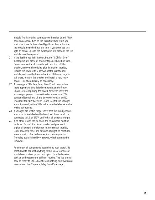
Troubleshooting (cont.)14.15.16.24Pump 1Pump 2BlowerTempSetupStatus12:00PM SETUP 100FWhite Audio Button – The Audio Module has a plug andplay feature, so if the button is white, it is not in place orsomehow not communicating with the Control Module.Turn off the circuit breaker and replace the Audio Module.White LEDS Button – The LED Module has a plug andplay feature, so if the button is white, it is not in place orsomehow not communicating with the Control Module.Turn off the circuit breaker and replace the LED Module.Possible Messages are:“Replace Fuse” (Excessive current has been drawn by amotor or the ozonator.) Go to step 17.“Replace Control Module” (Internal problems found.)The red module must be replaced.“COMM Error” (The Topside is unable to communicatewith Control Module.) Go to step 18.“Replace Relay Board” (A bad relay, current sensor, orjumper has been found.) Go to step 22.If no messages are showing and no buttons are white,allow approximately 2 minutes for a flow test to beperformed, and then proceed to test each function fornormal operation from the topside. Note that anytime abutton is pressed and a defect is seen by the self-testfunction, instead of green, the button will turn white. If awhite button appears, the associated equipment may needto be replaced.If the self-test function does not indicate any actionsto take, the balance of the troubleshooting mustbe performed by careful observations and possiblesubstitution as follows:A. TOP SIDE – If the touch screen does not changescreens, or the display is not normal, the Top Side mustbe replaced. (First verify that the screen is not locked, bygoing to “setup” and then “unlock”.)B. CONTROL MODULE – The Control Module is thebrain for the entire spa. If it has been damaged, certainfunctions may not be performed correctly. A quicksubstitution will verify the need to replace it.C. LED MODULE - All of the LED function is in this module.Replacement will solve most LED problems, other thanindividual LED outage.D. AUDIO MODULE – Replacement of this module shouldresolve any audio problem, other than individual speakerproblems (which can be isolated by swapping speakerwires).E. TEMPERATURE SENSOR – The sensor in the heatermeasures both water flow and water temperature. Ithas dual elements that monitor each other. The onlytime it would need replacement is if one of the elementsbecomes defective. This will be obvious because thetemperature readings for Heater 1 and Heater 2 on thestatus screen will be different by more than 20F, whichis a sign of trouble, since they are exposed to the sametemperature in the heater.17. Fuses can best be checked by hooking a voltmeterbetween L2 on the incoming power connector and theright hand side of each fuse. Any fuse that doesn’t havearound 230V on that side must be replaced. Replace with30A to avoid incidental blowing. If the fuse blows again,look for a problem with the pump or the motor.18. A message of “COMM Error” may be caused by improperseating of the red module. Before replacing the redmodule, turn off the circuit breaker and then remove thered module. Examine the circuit card inside the modulefor proper position. The edge of the card with the goldfingers should be about ¼ inch inside the edge of themodule. Note that it is free to move slightly inside themodule. If the card appears to be jammed out of position,due to excessive insertion force, an attempt to correct theproblem may be attempted. If it looks undamaged, go tostep 20.19. Remove the black o-ring around the module. Observe theposition of the white nylon guide hardware relative tothe card’s bottom side (no components). Insert a mediumscrewdriver into one of the small slots between the twohalves of the module and twist the screwdriver to popopen the module. Reposition the card, snap the moduleback together, and replace the o-ring.20. With the circuit breaker still off, replace the cover with 2screws and re-install the red module. Note that a gentleup and down movement will help the card inside the
module find its mating connector on the relay board. Nowhave an assistant turn on the circuit breaker while youwatch for three flashes of red light from the card insidethe module, near the back left side. If you don’t see thislight on power up, and the message is still present, the redmodule must be replaced.21. If the flashing red light is seen, but the “COMM Error”message is still present, another topside should be tried.Do not remove the old topside yet. Just turn off thebreaker, remove all modules, plug in another topside,replace the cover with 2 screws, install just the redmodule, and turn the breaker back on. If the message isstill there, turn off the breaker and install a new relayboard. (This should rarely be necessary.)22. A message of “ Replace Relay Board” will occur whenthere appears to be a failed component on the RelayBoard. Before replacing the board, however, verify theincoming ac power. Use a voltmeter to measure 120Vbetween Neutral and L1 and between Neutral and L2.Then look for 240V between L1 and L2. If these voltagesare not present, within 10%, call a qualified electrician forwiring corrections.23. If voltages are within range, verify that the 3 red jumpersare correctly installed on the board. All three should beconnected to L2, or 240V. Verify that all crimps are tight.24. If no other issues can be seen, the relay board must bereplaced. Turn off the circuit breaker and proceed tounplug all pumps, transformer, heater sensor, topside,LEDs, speakers, mp3, and antenna. It might be helpful tomake a sketch of actual connections before you start.The relay board is held by 4 screws, which can now beremoved.Re-connect all components according to your sketch. Becareful not to connect anything to the “AUX” connector,which has constant power on its pins. Turn the breakerback on and observe the self-test routine. The spa shouldnow be ready to use, since there is nothing else that couldhave caused the “Replace Relay Board” message.25


