download - Nuts & Volts Magazine
download - Nuts & Volts Magazine
download - Nuts & Volts Magazine
- No tags were found...

Create successful ePaper yourself
Turn your PDF publications into a flip-book with our unique Google optimized e-Paper software.
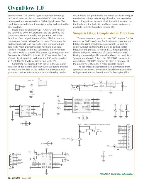
OvenFlow 1.0thermometers. The analog signal is between the rangeof 0 to +5 volts and fed to one of the PIC port pins tobe sampled and converted to a 10-bit digital value. Theresult is converted into a three-digit display and sent to theLCD readout.Board buttons labelled “Up,” “Down,” and “Select”are sensed by other PIC port pins and are used by thesoftware to control the relay, temperature, and timerfunctions. One helpful feature of the 16F88 is that youcan turn on “weak pull-ups” on its ports. This means thebutton inputs will read five volts when not pushed andzero volts when pushed without having to put extra“pull-up” resistors to the five volt supply. It’s no wonderthe board looks so simple! The power supply regulates thefive volts for all the ICs. A MAX232 IC converts the 0 to+5 volt digital signals to and from the PIC to the standard±12 volt RS-232 levels for interfacing to the PC.Something not supplied with the kit is the AC outletbox seen in the picture. The relay wires are run to this boxto switch the hot side of the outlets. An alternative thatyou may consider safer is to not mount the relay on thecircuit board but put it inside the outlet box itself and justrun the low voltage control signal back to the controllerboard. A significant amount of additional information onthe hardware, the build kit, and boot loader software isavailable from the SparkFun website [1].Simple is Okay; Complicated is More FunToaster ovens can get up to over 500 degrees F — hotenough for SMD soldering. But heat alone is not enough.It takes the right time/temperature profile to melt thesolder without destroying the parts or getting solderbridges in the process. A typical SMD heating profile isshown in Figure 3 (courtesy of Kester solder systems).Having a required profile was what drove the need for a“programmed mode.” Since the PIC16F88 can write itsown internal EEPROM memory to store a program, allthe pieces were there for a really capable circuit!The schematic is reproduced with permission fromSparkFun Electronics. The BoostC header file is providedwith permission from BoostSource Technologies. (TheJP112Temp-IN+INStatus_LEDR1330D2LG1LogoLOGOJ1DC PowerR1D11N4004R2PowerS1RAW1C1100uFU1VinGND2Vout78053VCCC2100uFJC1RS232+IN5948372611234567U3IN++C+TCOM-T-CV-AD595VCCGNDRX1INTX1OUT-IN-ALM+ALMV+COMPVOFBC80.1uFVCCStatusVCC16VCCGND13451110129VCCTXRXR610KS2ResetD6 1D7 2Temp 3VPP 4GNDCS156CS2 7RX 8Status_LED 9Relay_ControlC610uFC710uFR7U210KPIC16F88VCCRAWD31N4148Q1NPNC90.1uF181716151413121110D5D4ER/WVCCCS3RSTXRelay_Control2x Quick-Connect Solder Lug Connection to ToasterREL1SPST-NOR210KVCCVCCContrastCS1S3UpCS2S4DownGND 1VCC 2Contrast 3RS 4R/W 5E 678910D4 11D5 12D6 13D4D7 1415GND 161N4148CS3S5SelectLCD1RA2/AN2/VREF- RA1/AN1RA3/AN3/VREF+ RA0/AN0RA4/AN4 RA7/OSC1RA5/VPP/MCLR RA6/OSC2VSSVDDRB0/INT RB7/AN6/PGDRB1 RB6/AN5/PGCRB2/RXRB5/TXRB3RB414 -IN1312111098 TempC10VCC0.1uFVCCC4U4 MAX23210uF 2Vs+ C1+6Vs- C1-C5C2+C2-10uFTX1OUT 14T1Out T1In7T2Out T2InRX1IN 13R1In R1Out8R2In R2OutGNDVCCVEERSR/WED0D1D2D3D4D5D6D7BL+BL-LCD 16x215FIGURE 2. Controller schematic.68 June 2008