

CC20/25 Part Sheet - You are now at the Down-Load Site for Tol-O
CC20/25 Part Sheet - You are now at the Down-Load Site for Tol-O
CC20/25 Part Sheet - You are now at the Down-Load Site for Tol-O

Create successful ePaper yourself
Turn your PDF publications into a flip-book with our unique Google optimized e-Paper software.
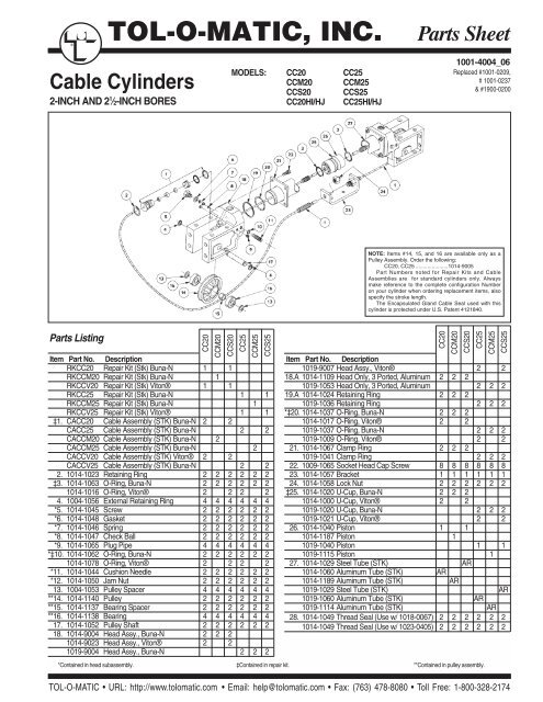
®TOL-O-MATIC, INC.<strong>Part</strong>s <strong>Sheet</strong>Cable Cylinders2-INCH AND 2 1 ⁄2-INCH BORESMODELS: <strong>CC20</strong> CC<strong>25</strong>CCM20 CCM<strong>25</strong>CCS20 CCS<strong>25</strong><strong>CC20</strong>HI/HJ CC<strong>25</strong>HI/HJ1001-4004_06Replaced #1001-0209,# 1001-0237& #1900-0200NOTE: Items #14, 15, and 16 <strong>are</strong> available only as aPulley Assembly. Order <strong>the</strong> following:<strong>CC20</strong>, CC<strong>25</strong> ......................1014-9005<strong>Part</strong> Numbers noted <strong>for</strong> Repair Kits and CableAssemblies <strong>are</strong> <strong>for</strong> standard cylinders only. Alwaysmake reference to <strong>the</strong> complete configur<strong>at</strong>ion Numberon your cylinder when ordering replacement items, alsospecify <strong>the</strong> stroke length.The Encapsul<strong>at</strong>ed Gland Cable Seal used with thiscylinder is protected under U.S. P<strong>at</strong>ent 4121840.<strong>Part</strong>s ListingItem <strong>Part</strong> No. DescriptionRK<strong>CC20</strong> Repair Kit (Stk) Buna-N 1 1RKCCM20 Repair Kit (Stk) Buna-N 1RKCCV20 Repair Kit (Stk) Viton® 1 1RKCC<strong>25</strong> Repair Kit (Stk) Buna-N 1 1RKCCM<strong>25</strong> Repair Kit (Stk) Buna-N 1RKCCV<strong>25</strong> Repair Kit (Stk) Viton® 1 1‡1. CA<strong>CC20</strong> Cable Assembly (STK) Buna-N 2 2CACC<strong>25</strong> Cable Assembly (STK) Buna-N 2 2CACCM20 Cable Assembly (STK) Buna-N 2CACCM<strong>25</strong> Cable Assembly (STK) Buna-N 2CACCV20 Cable Assembly (STK) Viton® 2 2CACCV<strong>25</strong> Cable Assembly (STK) Buna-N 2 22. 1014-1023 Retaining Ring 2 2 2 2 2 2‡3. 1014-1063 O-Ring, Buna-N 2 2 2 2 2 21014-1016 O-Ring, Viton® 2 2 2 24. 1004-1056 External Retaining Ring 4 4 4 4 4 4*5. 1014-1045 Screw 2 2 2 2 2 2*6. 1014-1048 Gasket 2 2 2 2 2 2*7. 1014-1046 Spring 2 2 2 2 2 2*8. 1014-1047 Check Ball 2 2 2 2 2 2*9. 1014-1065 Plug Pipe 4 4 4 4 4 4*‡10. 1014-1062 O-Ring, Buna-N 2 2 2 2 2 21014-1078 O-Ring, Viton® 2 2 2 2*11. 1014-1044 Cushion Needle 2 2 2 2 2 2*12. 1014-1050 Jam Nut 2 2 2 2 2 213. 1004-1053 Pulley Spacer 4 4 4 4 4 4**14. 1014-1140 Pulley 2 2 2 2 2 2**15. 1014-1137 Bearing Spacer 2 2 2 2 2 2**16. 1014-1138 Bearing 4 4 4 4 4 417. 1014-1052 Pulley Shaft 2 2 2 2 2 218. 1014-9004 Head Assy., Buna-N 2 2 21014-9023 Head Assy., Viton® 2 21019-9004 Head Assy., Buna-N 2 2 2<strong>CC20</strong>CCM20CCS20CC<strong>25</strong>CCM<strong>25</strong>CCS<strong>25</strong>Item <strong>Part</strong> No. Description1019-9007 Head Assy., Viton® 2 218.A 1014-1109 Head Only, 3 Ported, Aluminum 2 2 21019-1053 Head Only, 3 Ported, Aluminum 2 2 219.A 1014-1024 Retaining Ring 2 2 21019-1036 Retaining Ring 2 2 2*‡20. 1014-1037 O-Ring, Buna-N 2 2 21014-1017 O-Ring, Viton® 2 21019-1037 O-Ring, Buna-N 2 2 21019-1009 O-Ring, Viton® 2 221. 1014-1067 Clamp Ring 2 2 21019-1041 Clamp Ring 2 2 222. 1009-1065 Socket Head Cap Screw 8 8 8 8 8 823. 1014-1057 Bracket 1 1 1 1 1 124. 1014-1058 Lock Nut 2 2 2 2 2 2‡<strong>25</strong>. 1014-1020 U-Cup, Buna-N 2 2 21014-1000 U-Cup, Viton® 2 21019-1020 U-Cup, Buna-N 2 2 21019-1021 U-Cup, Viton® 2 226. 1014-1040 Piston 1 11014-1187 Piston 11019-1040 Piston 1 11019-1115 Piston 127. 1014-1029 Steel Tube (STK) AR1014-1060 Aluminum Tube (STK) AR1014-1189 Aluminum Tube (STK) AR1019-1029 Steel Tube (STK) AR1019-1060 Aluminum Tube (STK) AR1019-1114 Aluminum Tube (STK) AR28. 1014-1049 Thread Seal (Use w/ 1018-0067) 2 2 2 2 2 21014-1049 Thread Seal (Use w/ 1023-0405) 2 2 2 2 2 2*Contained in head subassembly. ‡Contained in repair kit. **Contained in pulley assembly.TOL-O-MATIC • URL: http://www.tolom<strong>at</strong>ic.com • Email: help@tolom<strong>at</strong>ic.com • Fax: (763) 478-8080 • <strong>Tol</strong>l Free: 1-800-328-2174<strong>CC20</strong>CCM20CCS20CC<strong>25</strong>CCM<strong>25</strong>CCS<strong>25</strong>
2– General Install<strong>at</strong>ion and Maintenance Instructions CC(M)20, CC(M)<strong>25</strong> <strong>Part</strong>s <strong>Sheet</strong> #1001-4004_06INSTALLATIONWhen unpacking a <strong>Tol</strong>-O-M<strong>at</strong>ic cable cylinder, BE EXTRA CAREFUL NOT TOSCRATCH OR MAR THE NYLON COVERING ON THE CABLE. The cylindermay be mounted using <strong>the</strong> bolt holes in <strong>the</strong> head. When <strong>at</strong>taching <strong>the</strong> cable bracketto <strong>the</strong> driven mechanism, be sure it is in perfect alignment and th<strong>at</strong> it does notdeflect <strong>the</strong> cable to <strong>the</strong> side. Misalignment can cause excessive seal wear.Pretensioning and proof-loading instructions: All double-acting cable cylinders<strong>are</strong> shipped without being pretensioned. They must be pretensioned aftermounting to insure maximum service life of <strong>the</strong> device. There <strong>are</strong> two types ofstretch in cable— constructional and elastic. The constructional stretch isremoved by proof-loading of <strong>the</strong> cable. The elastic stretch is removed by properpretensioning of <strong>the</strong> cable.Proof-loading of cables (<strong>for</strong> cylinders without Auto Tensioners)1. Tighten <strong>the</strong> bracket terminal lock nuts equally with a torque wrench totorque requirements listed in Table A.2. Let set <strong>for</strong> 30 seconds.3. Loosen lock nuts to remove tension. (But leave <strong>the</strong>m tight enough toelimin<strong>at</strong>e any slack.)4. Follow Pretensioning Instructions.TABLE A: TORQUE TO PROOF-LOAD THE CABLEMODELREQUIRED TORQUE<strong>CC20</strong> and CC<strong>25</strong> 115 inch-pounds OR 12.99 Newton-metersPretensioning of cables:1. Block <strong>the</strong> load some distance from <strong>the</strong> end of travel to keep cylinderfrom bottoming.2. Apply pressure th<strong>at</strong> is 15-20 percent higher than actual load pressureneeded to move <strong>the</strong> load.NOTE: <strong>Load</strong> pressure is defined as <strong>the</strong> actual pressure required to move <strong>the</strong>load. When <strong>the</strong> load is stopped externally be<strong>for</strong>e <strong>the</strong> piston bottoms, <strong>the</strong> reliefvalve or regul<strong>at</strong>or setting becomes <strong>the</strong> load pressure.TO REBUILD THE CYLINDER1. Remove cylinder from machinery.2. Disconnect Cable (1) from <strong>the</strong> Clevis (23) and remove Pulleys (14) on bo<strong>the</strong>nds of <strong>the</strong> cylinder.3. Remove one Head (18) from cylinder by removing <strong>the</strong> four CapScrews (22).4. Pull Piston (26) towards <strong>the</strong> open tube end and remove from Tube (27).5. Disconnect Cable Assembly (1) from Piston (26).6. Install new U-cups (<strong>25</strong>) and O-rings (3) on Piston (26).7. Being c<strong>are</strong>ful not to damage <strong>the</strong> cable, lubric<strong>at</strong>e and install <strong>the</strong> Gland Sealson <strong>the</strong> Cable Assembly (1) in <strong>the</strong> Heads (18), and reinstall <strong>the</strong> RetainingRings (2).8. Push <strong>the</strong> Piston (26) back into Tube (27) by gently tucking in <strong>the</strong> U-cup (<strong>25</strong>)with a screwdriver or pencil. Mount head back on cylinder with Socket HeadCap Screws (22). Replace <strong>the</strong> Pulleys (14) and connect Cable Assembly (1) toclevis (23).9. Oper<strong>at</strong>e cylinder back and <strong>for</strong>th by hand several times to be sure it is properlyassembled be<strong>for</strong>e reconnecting air or hydraulic service.10. Reinstall cylinder on machinery.IMPORTANT NOTE: Apply (Blue) Loctite® #242 or equivalent to threaded cableterminal be<strong>for</strong>e connecting to <strong>the</strong> piston.MAINTENANCEKeep <strong>the</strong> cylinder as clean as possible around pulleys, glands, etc. Pneum<strong>at</strong>ic serviceshould be adequ<strong>at</strong>ely lubric<strong>at</strong>ed with SAE 10 or 20 grade non-detergent oil. Pulleyshave permanently lubric<strong>at</strong>ed bearings and will require no maintenance. Check <strong>the</strong>cylinder’s cables periodically to help prevent prem<strong>at</strong>ure or unexpected failures.<strong>You</strong>r <strong>Tol</strong>-O-M<strong>at</strong>ic Cable Cylinder will give you many cycles of trouble free service.However, should a leak occur, a rebuilding kit may be obtained whichenables you to replace all <strong>the</strong> seals in a cylinder to return it to normal oper<strong>at</strong>ingcondition.When pressurized, one cable becomes tight and <strong>the</strong> o<strong>the</strong>r becomes slack.Manually adjust out <strong>the</strong> slack. Release <strong>the</strong> pressure. Block <strong>the</strong> load on <strong>the</strong>opposite side and pressurize <strong>the</strong> o<strong>the</strong>r port. Repe<strong>at</strong> <strong>the</strong> manual adjustmenton <strong>the</strong> o<strong>the</strong>r cable. Release pressure and remove blocks. Return <strong>the</strong> regul<strong>at</strong>oror relief valve to <strong>the</strong> original load pressure.The cylinder is <strong>now</strong> pretensioned. Additional manual adjustment should notbe required. It is suggested however, th<strong>at</strong> <strong>the</strong> cables be checked periodically.Altern<strong>at</strong>e Method: If <strong>the</strong> load cannot be blocked <strong>for</strong> cable pretensioning asst<strong>at</strong>ed above, tighten <strong>the</strong> bracket terminal lock nuts with a torque wrench tototal pretensioning torque as st<strong>at</strong>ed in Table B.TABLE B: TORQUE FOR UNBLOCKABLE LOADSPretensioning + Starting Torque of = TotalModel Torque Terminal Nuts Pretensioning Torque<strong>CC20</strong> 46.0 in-lbs. + <strong>25</strong>.0 in.-lbs. = 71.0 in.-lbs.5.2 N-m + 2.82 N-m = 8.02 N-mCC<strong>25</strong> 73.0 in-lbs. + <strong>25</strong>.0 in.-lbs. = 98.0 in.-lbs.8.<strong>25</strong> N-m + 2.82 N-m = 11.07 N-mNOTE: For cylinders with Auto Tensioners, <strong>the</strong> cables must be proof-loaded andpretensioned be<strong>for</strong>e pressure is applied to <strong>the</strong> AT unit.TOL-O-MATIC • URL: http://www.tolom<strong>at</strong>ic.com • Email: help@tolom<strong>at</strong>ic.com • Fax: (763) 478-8080 • <strong>Tol</strong>l Free: 1-800-328-2174
<strong>Part</strong>s <strong>Sheet</strong> #1001-4004_06 CC(M)20, CC(M)<strong>25</strong> Optional Accessories – 3OPTIONAL REED SWITCHOPTIONAL AUTO TENSIONERNOTE: Every <strong>Tol</strong>-O-M<strong>at</strong>ic Cable Cylinder has its stroke length indic<strong>at</strong>ed on<strong>the</strong> identific<strong>at</strong>ion tag shipped with <strong>the</strong> cylinder. Refer to this stroke measurementwhen ordering replacement parts <strong>for</strong> <strong>the</strong> cylinder.Should <strong>the</strong> tag be missing, measure <strong>the</strong> length of <strong>the</strong> cylinder including <strong>the</strong>heads <strong>at</strong> both ends. If <strong>the</strong>re <strong>are</strong> no switches present on <strong>the</strong> cylinder, check<strong>the</strong> piston <strong>for</strong> a magnet to see if it is a Reed Switch model. If it is, consult <strong>the</strong><strong>Tol</strong>-O-M<strong>at</strong>ic Cable Cylinder c<strong>at</strong>alog dimensional drawings <strong>for</strong> “stroke-plus”length and subtract 1.62 inches <strong>for</strong> cylinders with 1/2-inch 3/4-inch and 1-inch bores and .375 inches <strong>for</strong> all larger bore Reed Switch models to determine<strong>the</strong> stroke length.OPTIONAL ACCESSORIESPART LISTING<strong>CC20</strong>REED SWITCHItem <strong>Part</strong> No. Description29. 3600-9082 Switch, Reed, Form A, 5M Wire AR AR3600-9083 Switch, Reed, Form A, Male Connect AR AR3600-9084 Switch, Reed, Form C, 5M Wire AR AR3600-9085 Switch, Reed, Form C, Male Connect AR AR3600-9086 Switch, Triac, 5M Wire AR AR3600-9087 Switch, Triac, Male Connect AR AR30. <strong>25</strong>03-1042 Clamp AR AR30. <strong>25</strong>03-1043 Clamp AR AR32. 1014-1188 Magnet 11019-1116 Magnet 1<strong>CC20</strong>CCM20CCM20CCS20CCS20CC<strong>25</strong>CC<strong>25</strong>CCM<strong>25</strong>CCM<strong>25</strong>AUTO TENSIONER KITSItem <strong>Part</strong> No. Description1014-9012 Tensioner Kit Assembly <strong>CC20</strong> 1 1 1 – – –1014-9134 Tensioner Kit Assembly <strong>CC20</strong>3 Ported Head 1 1 1 – – –1019-9005 Tensioner Kit Assembly CC<strong>25</strong> – – – 1 1 1CCS<strong>25</strong>CCS<strong>25</strong><strong>CC20</strong>CCM20CCS20CC<strong>25</strong>CCM<strong>25</strong>AUTO TENSIONERItem <strong>Part</strong> No. Description33. 1014-1138 Sealed Ball Bearing 2 2 2 2 2 234. 1014-1140 Pulley 1 1 1 1 1 135. 1014-1137 Bearing Spacer 1 1 1 1 1 163. 1014-9005 Pulley Assembly 2 2 2 2 2 236. 1014-1045 Hex Head Bolt 1 1 1 1 1 137. 1014-1048 Check Valve Gasket 1 1 1 1 1 138. 1014-1046 Check Valve Spring 1 1 1 1 1 139. 1014-1047 Check Valve Ball 1 1 1 1 1 140. 1014-1108 Tensioner Head 1 1 11014-1106 Tensioner Head, 3-ported head 1 1 11019-1043 Tensioner Head 1 1 11019-1113 Tensioner Head, 3-ported head 1 1 141. 1014-1062 O-Ring, Buna-N 1 1 1 1 1 142. 1014-1044 Cushion Adjustment Needle 1 1 1 1 1 143. 1014-1049 Thread Seal 1 1 1 1 1 144. 1014-1050 Hex Head Jam Nut 1 1 1 1 1 145. 1014-1065 Pipe Plug 2 2 2 2 2 246. 1014-1052 Pulley Shaft 1 1 1 1 1 147. 1004-1056 Retaining Ring 2 2 2 2 2 248. 1014-1172 Back Pl<strong>at</strong>e 1 1 1 1 1 149. 0768-1022 Hex Head Bre<strong>at</strong>her Pipe Plug 1 1 1 1 1 150. 1014-1173 Front Tensioner Pl<strong>at</strong>e 1 1 1 1 1 151. 1014-8011 Side Spacer 2 2 2 2 2 <strong>25</strong>2. 1900-1005 Piston Shaft 1 1 1 1 1 153. 0701-1004 O-Ring, Buna-N 1 1 1 1 1 154. 1039-1045 Hex Head Bolt 1 1 1 1 1 155. 0774-1003 Fl<strong>at</strong> Washer 1 1 1 1 1 156. 1014-8026 Tie Pl<strong>at</strong>e 1 1 1 1 1 157. 1309-2021 Cap Screw 4 4 4 4 4 458. 1900-1009 Socket Head Cap Screw 4 4 4 4 4 459. 1900-1002 Tensioner Tube 1 1 1 1 1 160. 1900-1004 Piston 1 1 1 1 1 161. 1014-1083 O-Ring, Buna-N 1 1 1 1 1 162. 1029-1037 O-Ring, Buna-N 1 1 1 1 1 1CCS<strong>25</strong>TOL-O-MATIC • URL: http://www.tolom<strong>at</strong>ic.com • Email: help@tolom<strong>at</strong>ic.com • Fax: (763) 478-8080 • <strong>Tol</strong>l Free: 1-800-328-2174
4 – Optional Accessories (cont.) CC(M)20, CC(M)<strong>25</strong> <strong>Part</strong>s <strong>Sheet</strong> #1001-4004_06AUTO TENSIONER OPTIONAll cable cylinder models with Auto Tensioner units should be plumbed witha separ<strong>at</strong>e, non-fluctu<strong>at</strong>ing pressure source which is a set percentage of <strong>the</strong>actual oper<strong>at</strong>ing pressure.BORE SIZE (in.)% OF LOAD PRESSURE.75 22%1.0 40%1.5 86%2.0 32%2.0 (500 PSI) 24%2.5 51%3.0 54%4.0 96%5.0 75%6.0 57%8.0 102%UNIVERSAL SWITCH WIRING DIAGRAMS ANDLABEL COLOR CODING(+)(-)OR(+)(-)LOADLOADBROWN(+)BLUE(-)BROWN(+)BLUE(-)REEDSWITCHREEDSWITCHREED SWITCH FORM ALABEL COLOR: RED10VA MAX.200 Vdc500mA Max. CurrentCOMMONNORMALLY CLOSEDNORMALLY OPENBROWNBLACKBLUEREEDSWITCHREED SWITCH FORM CLABEL COLOR: YELLOW120 Vdc/120 Vac MAX.<strong>25</strong>0mA Max. CurrentIn <strong>the</strong> above table, load pressure is defined as <strong>the</strong> pressure required tomove <strong>the</strong> load, NOT <strong>the</strong> regul<strong>at</strong>ed pressure (pneum<strong>at</strong>ic) or <strong>the</strong> relief valvesetting (hydraulic).NOTE: If <strong>the</strong> load will be stopped mechanically prior to <strong>the</strong> piston bottoming,<strong>the</strong>n <strong>the</strong> regul<strong>at</strong>or pressure or <strong>the</strong> relief valve setting must be considered tobe <strong>the</strong> load pressure.If <strong>the</strong> applic<strong>at</strong>ion is hydraulic, a pressure-reducing valve must be used toensure a non-fluctu<strong>at</strong>ing pressure source to <strong>the</strong> tensioner(s) or <strong>the</strong> pressuresource must be an independent circuit th<strong>at</strong> will maintain <strong>the</strong> requireddifferential.When installing cable cylinder models with Auto tensioner units, take up <strong>the</strong>cable slack manually according to <strong>the</strong> pretensioning instructions underGeneral Install<strong>at</strong>ion and MaintenanceREED SWITCHESNOTE: Form A Reed Switches should not be used in TTL logic circuits. Avoltage drop caused by <strong>the</strong> L.E.D. indic<strong>at</strong>or will result.For applic<strong>at</strong>ions whereTTL circuits <strong>are</strong> used, please contact <strong>the</strong> factory.WARNING: An ohmmeter is recommended <strong>for</strong> testing Reed Switches.NEVER use an incandescent light bulb as a high current rush may damage<strong>the</strong> switch.Reed and TRIAC switches <strong>are</strong> only recommended <strong>for</strong> signalling position,not directly powering soleniods. For shifting a solenoid, a relay or resistor isrecommended between it and <strong>the</strong> Reed Switch. Switch r<strong>at</strong>ings must not beexceeded <strong>at</strong> any time.TO ORDER RETROFIT KITS: SW (<strong>the</strong>n <strong>the</strong> model number and base size,and code <strong>for</strong> type of switch needed: EXAMPLE: SWCC10RT120VacMax.BLUEMOVTRIACSWITCHACCOMLOADBROWNINPUTTRIAC SWITCHLABEL COLOR: BLUEMax. 1Amp. Cont. Current @ 86°FMax. .5Amp. Cont. Current @ 140°FPeak surge current 10Amp.NOTE: The side of <strong>the</strong> switch with<strong>the</strong> groove indic<strong>at</strong>es <strong>the</strong> sensingsurface. This must face toward <strong>the</strong>magnet.BLUEBLACKBROWNQUICK-DISCONNECT(Applies to all switch types)An Important Note RegardingField Retrofit of Quick-DisconnectCouplers:If replacing a Quick-Disconnectswitch manufactured be<strong>for</strong>e 7-1-97it will also be necessary to replaceor rewire <strong>the</strong> female-end couplerwith <strong>the</strong> in-line splice<strong>25</strong>03-10<strong>25</strong> Female Connector 5MBTBMRTRMCTCMSWITCH TYPE CODE(Form C Reed Switch with 5-meter lead)(Form C Reed Switch with 5-meter lead and QD)(Form A Reed Switch with 5-meter lead)(Form A Reed Switch with 5-meter lead and QD)(TRIAC Switch with 5-meter lead)(TRIAC Switch with 5-meter lead and QD)All Switch Kits come with1 switch and mountinghardw<strong>are</strong>.Hardw<strong>are</strong> Only Kits <strong>are</strong> available:CCM20-<strong>25</strong>03-1042 andCCM<strong>25</strong>-<strong>25</strong>03-1043.For complete Reed and TRIAC Switch Per<strong>for</strong>mance D<strong>at</strong>a, refer to <strong>the</strong><strong>Tol</strong>-O-M<strong>at</strong>ic Fluid Power Products C<strong>at</strong>alog #9900-4000.Loctite® is a registered trademark of <strong>the</strong> Loctite Corpor<strong>at</strong>ion, www.loctite.comViton® is a registered trademark of <strong>the</strong> E.I. Du Pont de Newmours Co., www.dupont.com®TOL-O-MATIC, INC.3800 County Road 116, Hamel, MN 55340http://www.<strong>Tol</strong>om<strong>at</strong>ic.com • Email: Help@<strong>Tol</strong>om<strong>at</strong>ic.comPhone: (763) 478-8000 • Fax: (763) 478-8080 • <strong>Tol</strong>l Free: 1-800-328-2174© 2006 TOL-O-MATIC, INC.In<strong>for</strong>m<strong>at</strong>ion furnished is believed to be accur<strong>at</strong>eand reliable. However, <strong>Tol</strong>-O-M<strong>at</strong>ic assumes noresponsibility <strong>for</strong> its use or <strong>for</strong> any errors th<strong>at</strong> mayappear in this document. <strong>Tol</strong>-O-M<strong>at</strong>ic reserves <strong>the</strong>right to change <strong>the</strong> design or oper<strong>at</strong>ion of <strong>the</strong>equipment described herein and any associ<strong>at</strong>edmotion products without notice. In<strong>for</strong>m<strong>at</strong>ion in thisdocument is subject to change without notice.


