B3W rodless Belt drIVeN actuator - You are now at the Down-Load ...
B3W rodless Belt drIVeN actuator - You are now at the Down-Load ...
B3W rodless Belt drIVeN actuator - You are now at the Down-Load ...
- No tags were found...
You also want an ePaper? Increase the reach of your titles
YUMPU automatically turns print PDFs into web optimized ePapers that Google loves.
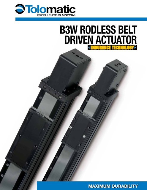
A<strong>B3W</strong> Rodless <strong>Belt</strong> Driven Actu<strong>at</strong>orBmxemxBb3sb3wtksRODLESS ACTUATORStkbbcsslsICRThe <strong>B3W</strong> <strong>rodless</strong> style <strong>actu<strong>at</strong>or</strong> is designedfor carrying moder<strong>at</strong>e to heavy loads <strong>at</strong>moder<strong>at</strong>e to high speeds with large bendingmoment capacities. Based upon <strong>the</strong> BC3pneum<strong>at</strong>ic band cylinder, with our exclusivefe<strong>at</strong>ures, itutilizes a p<strong>at</strong>ented integral recircul<strong>at</strong>ing ballbearing guidance system th<strong>at</strong> providesconsistent and durable performance. Each<strong>B3W</strong> is built-to-order in stroke lengths up to292 inches. Nobody k<strong>now</strong>s <strong>rodless</strong> likeTolom<strong>at</strong>ic, and <strong>the</strong> <strong>B3W</strong> proves it.• Low profile to fit your applic<strong>at</strong>ion• High precision bearings fe<strong>at</strong>ure smooth, lowbreakaway motion• Highest load and bending moment capacitiesIMAgswarsaROD STYLE ACTUATORSA COMPARISON OF BELT DRIVE ACTUATORSAll Tolom<strong>at</strong>ic belt drive <strong>actu<strong>at</strong>or</strong>s fe<strong>at</strong>ure:• High linear velocity • High acceler<strong>at</strong>ion r<strong>at</strong>e • Long stroke lengths• Excellent repe<strong>at</strong>ability • High duty cycles • Low profileUnique fe<strong>at</strong>ures include:MXB-U Electric <strong>Belt</strong> Drive MXB-P Electric <strong>Belt</strong> Drive <strong>B3W</strong> Electric <strong>Belt</strong> Drive TKB Electric <strong>Belt</strong> DrivegsamrvmrsGEARBOXSwItCHCONTROL SYSTEMS +• Requires external guidanceand support• High load and bending moment capacities• High precision bearingsfe<strong>at</strong>ure smooth, low breakaway motion• Durable profiled rail designuses THK ® Caged Ball ®technology to reduce frictionand extend <strong>actu<strong>at</strong>or</strong> lifewww.tolom<strong>at</strong>ic.com for complete inform<strong>at</strong>ion, search by liter<strong>at</strong>ure number:#8500-4000 #8500-4000 #3600-4148 #3600-4609• Superior rigidity, high momentloads• Straightness and fl<strong>at</strong>nesswithin 0.0002 inches per inchof stroke• Wide stable pl<strong>at</strong>form for XYapplic<strong>at</strong>ions• Lowest carrier deflection ofany Tolom<strong>at</strong>ic <strong>actu<strong>at</strong>or</strong>C<strong>B3W</strong>_2 1-800-328-2174 www.tolom<strong>at</strong>ic.com
A Comparison of Tolom<strong>at</strong>ic <strong>Belt</strong> Drive Actu<strong>at</strong>orsAPPLICATIONSA <strong>rodless</strong> belt <strong>actu<strong>at</strong>or</strong> integr<strong>at</strong>es <strong>the</strong>advantages of a linear belt solution with aload support and guidance system. Thiscombin<strong>at</strong>ion allows you to install a preassembledand compact solution, oftenwithout <strong>the</strong> need of external guide rails orload support systems. Available in multipleframe sizes with options such as dual carriersand dual support systems, you can chooseapplic<strong>at</strong>ion: High Speed Flying Cut Off+Test st<strong>at</strong>ions+Product handling+Camera positioningapplic<strong>at</strong>ion: X-Y Multi Axis<strong>the</strong> proper level of load and moment supportrequired for your applic<strong>at</strong>ion. The result ofthis combin<strong>at</strong>ion is a belt <strong>actu<strong>at</strong>or</strong> th<strong>at</strong> is:• Easy to size, design and order• Quick to install and maintain• Simple to integr<strong>at</strong>e and control• Provides a lower installed costCONTENTSRODLESS ACTUATORSROD STYLE ACTUATORSABmxemxB<strong>B3W</strong> <strong>Belt</strong> Drive Actu<strong>at</strong>or.. 2<strong>Belt</strong> Drive Comparison........2b3sApplic<strong>at</strong>ions .......................3<strong>Belt</strong> Construction................4b3w<strong>Belt</strong> Drive Advantages.........4<strong>B3W</strong> Performance........... 5tks<strong>B3W</strong> Fe<strong>at</strong>ures.................. 6tkbSpecific<strong>at</strong>ions................... 8Bending Moments .......... 9bcs<strong>Load</strong> Deflection ............. 10Auxiliary Carrier.............. 11slsDimensions...............12-17ICR<strong>B3W</strong>10..............................12Dual 180........................13IMA<strong>B3W</strong>15..............................14Dual 180........................15gswa<strong>B3W</strong>20..............................16Dual 180........................17rsaMotor Orient<strong>at</strong>ion........... 18+Laser marking+M<strong>at</strong>erial cutting+Adhesive dispensingFREE downloads <strong>at</strong> www.tolom<strong>at</strong>ic.com:• Sizing & Selection Softw<strong>are</strong>• 3D Solid ModelsApplic<strong>at</strong>ion D<strong>at</strong>agsaWorksheet .................... 19Selection Guidelines ...... 20CONTROL SYSTEMS +mrvSwitches........................ 21mrsOrdering......................... 23O<strong>the</strong>r Tolom<strong>at</strong>icProducts........................ 24GEARBOXSwItCHC1-800-328-2174 www.tolom<strong>at</strong>ic.com<strong>B3W</strong>_3
ABmxemxBb3sb3wtkstkbRODLESS ACTUATORS<strong>B3W</strong> Rodless <strong>Belt</strong> Driven Actu<strong>at</strong>orFEATURESADVANTAGES OF BELT SOLUTIONSThe use of synchronous belts, often• Long length strokesreferred to as timing belts, have become astandard in <strong>the</strong> autom<strong>at</strong>ed motion industry• High repe<strong>at</strong>abilityas an altern<strong>at</strong>e to screw drive mechanisms • High duty cyclesfor producing linear motion.A belt solution is ideal for linear positioningThis design for linear motion provides an and gantry applic<strong>at</strong>ions. Linear velocitiesexcellent solution for applic<strong>at</strong>ions th<strong>at</strong> can <strong>now</strong> reach up to 200 in/sec withrequire:acceler<strong>at</strong>ion r<strong>at</strong>es <strong>at</strong> 1200 in/sec 2 . <strong>Belt</strong>ing• High-speed linear velocitiesm<strong>at</strong>erial is available in lengths th<strong>at</strong> allowstroke lengths over 24 feet, two to three• High acceler<strong>at</strong>ion r<strong>at</strong>estimes longer than screw <strong>actu<strong>at</strong>or</strong>s.BELT CONSTRUCTIONbcsslsICRIMAgswarsaROD STYLE ACTUATORSTolom<strong>at</strong>ic installs an HTD synchronous belt in<strong>the</strong> <strong>B3W</strong> product line th<strong>at</strong> fe<strong>at</strong>ures a curvilineartooth profile. This type of tooth profiledistributes tooth load more evenly and providesgre<strong>at</strong>er tooth shear strength, allowing forhigher thrust loading. The deep teeth of <strong>the</strong>HTD profile <strong>are</strong> more cogging-resistant <strong>at</strong> agiven tension, preventing potentially damagingpositioning errors.Tolom<strong>at</strong>ic's standard belt is a polyurethanem<strong>at</strong>erial reinforced with steel tension membersto produce high carrier thrusts without beltstretch. A Kevlar ® reinforced belt fe<strong>at</strong>uringequal thrust capability is also available forapplic<strong>at</strong>ionsth<strong>at</strong> mayexperiencehigh shockloading.TensionMemberCURVILINEARTolom<strong>at</strong>ic’s tooth belt profiledistributes load evenly.gsamrvmrsGEARBOXCONTROL SYSTEMS +World class performance,five days built-to-order andlegendary customer service …wh<strong>at</strong> you expect from <strong>the</strong><strong>rodless</strong> leader . . .SwItCHC<strong>B3W</strong>_4 1-800-328-2174 www.tolom<strong>at</strong>ic.com
<strong>B3W</strong> Rodless <strong>Belt</strong> Driven Actu<strong>at</strong>orPERFORMANCEINPUT RPM2,5002,0001,5001,000500CARRIER SPEED CAPABILITIESLINEAR VELOCITY (mm/sec)0 1,2702,540 3,8105,0803,000<strong>B3W</strong>10<strong>B3W</strong>15<strong>B3W</strong>2000 50100 150200LINEAR VELOCITY (in/sec)MAXIMUM BELT THRUSTMAXIMUM BELT THRUST (lbf.)350300250200150100500150<strong>B3W</strong>10 / M3W10250<strong>B3W</strong>15 / M3W15325<strong>B3W</strong>20 / M3W201.561.331.11.89.67.44.220sizing softw<strong>are</strong>available <strong>at</strong> www.tolom<strong>at</strong>ic.comMAXIMUM BELT THRUST (kN)RODLESS ACTUATORSABmxemxBb3sb3wtkstkbbcsslsMAXIMUM ACCELERATION AS A FUNCTION OF LOAD WEIGHTICR1,2001,0004591136181227272318363WEIGHT (kg.)40845449954459063568072677181686290795330.525.4ROD STYLE ACTUATORSIMAgswarsaACCELERATION (in./sec. 2 )8006004002000100200300<strong>B3W</strong>104005006007008009001000WEIGHT (lb.)<strong>B3W</strong>151100120013001400150016001700<strong>B3W</strong>20180019002000210020.315.210.25.10ACCELERATION (m/sec. 2 )CONTROL SYSTEMS +gsamrvmrsGEARBOXSwItCHC1-800-328-2174 www.tolom<strong>at</strong>ic.com<strong>B3W</strong>_5
AB<strong>B3W</strong> Rodless <strong>Belt</strong> Driven Actu<strong>at</strong>orSPECIFICATIONSLOAD DEFLECTIONsizing softw<strong>are</strong>available <strong>at</strong> www.tolom<strong>at</strong>ic.commxeDEFLECTION ABOUT X AXISDEFLECTION ABOUT Y AXISmxBb3sDEFLECTION TESTING WAS DONE UNDER THESE CRITERIA:1.) Actu<strong>at</strong>or was properly mounted with distance between supports within recommend<strong>at</strong>ions(see Support Recommend<strong>at</strong>ions below)2.) Deflection was measured from center of carrier as shown (Mx = 13", My = 8")b3wtkstkbbcsslsICRRODLESS ACTUATORSDEFLECTION <strong>at</strong> 13 in (in)Mx (N-m)0 18 36 54 72 90 108 127 145 163 1810.1604.0640.1400.1200.1000.0800.0600.0400.02015 10 200 00 160 320 480 640 800 960 1120 1360 1520 1680Mx (in-lb)3.5563.0482.5402.0321.5241.016.508DEFLECTION <strong>at</strong> 330 mm (mm)DEFLECTION <strong>at</strong> 8 in (in)My (N-m)0 18 36 54 72 90 108 127 145 163 1810.0160.40640.01400.01200.01000.00800.00600.00400.002015 10 200 00 160 320 480 640 800 960 1120 1360 1520 1680My (in-lb).3556.3048.2540.2032.1524.1016.0508DEFLECTION <strong>at</strong> 203 mm (mm)IMAgswarsagsamrvmrsGEARBOXSwItCHROD STYLE ACTUATORSCONTROL SYSTEMS +LOAD WEIGHT (lbf)1,200900600300SUPPORT RECOMMENDATIONSMAX DISTANCE BETWEEN SUPPORTS (mm) “L”0 100 200 300 400 500 600 700 800 9002,1001,8001,500MAXIMUM LOADMAXIMUM LOADMAXIMUM LOAD2010 1500 6 12 18 24 30 36MAX DISTANCE BETWEEN SUPPORTS (in) “L”Weight9,0008,0007,0006,0005,0004,0003,0002,0001,0000LOAD WEIGHT (N)FRICTION FORCE (lb)FRICTION FORCELOAD WEIGHT (kg)0 91 181 272 363 454 544 635 816 9075.04.03.02.01.020151000 200 400 600 800 1,000 1,200 1,400 1,600 1,800 2,000LOAD WEIGHT (lb)22.217.813.38.94.4FRICTION FORCE (N)CL<strong>B3W</strong>_101-800-328-2174 www.tolom<strong>at</strong>ic.com
ABmxemxBb3sb3wtkstkbbcsslsICRIMAgswarsagsamrvmrsGEARBOXSwItCHCRODLESS ACTUATORSROD STYLE ACTUATORSCONTROL SYSTEMS +<strong>B3W</strong>10 Rodless <strong>Belt</strong> Driven Actu<strong>at</strong>orDIMENSIONS6.23[158.1]STROKE3.84[97.5].068[1.73]6.23[158.1]<strong>B3W</strong>10 ACTUATOR AND OPTIONS1.50[38.1]1.47[37.4]OPTIONAL SWITCHMOUNTING ❸ ❹ ❺.500 [12.70]1.250 [31.75]3.13 [79.4]45ϒ0.10[2.6]❶ ONE STUB SHAFT IS STANDARD ONALL <strong>B3W</strong> ACTUATORS❷ DOWEL PINS .003 (.08mm) MCARRIERPILOT LOCATORO.D. Ø 2.635 [66.93]I.D. Ø 2.25 [57.2]x 0.13 [3.2].178[4.5]SHOWN SDLOPTIONALMOUNTINGPLATES1.781 [45.24]0.89 [22.6]#10-24 x 0.50 DP[M5x0.8 x 1.27 DP]4 EQ SPACED ONØ 3.536 [89.81] B.C.4 AS SHOWN,4 OPPOSITESENSINGSURFACE0.250 [6.35]OPTIONAL 2.75 2.250TUBE [69.9] [57.15]SUPPORTS0.21[5.4]4.08[103.6]2.250[57.15]1.53[38.9]1.125[28.58]OPTIONALSTUB SHAFT ❶1.76[44.7]1.09 [27.8]BORECENTERLINE1.76[44.6] .76[19.4]1.922[48.81].27[6.8] 2.19 [55.6]❸ CAUTION: DO NOT OVERTIGHTEN SWITCHHARDWARE WHEN INSTALLING❹ NOTE: The scored face of <strong>the</strong> switch indic<strong>at</strong>es <strong>the</strong>sensing surface and must face toward<strong>the</strong> magnetØ .206[5.23]THRU (2)Ø .206[5.23]THRU (4)Ø.499[12.67]❷Ø .252/.251 x 0.25[6.045/6.020 x 6.4]DOWEL HOLE (2)1/4-20 [M6 x 1.0]TAPPED HOLE (4)1.50[38.1]Unless o<strong>the</strong>rwise noted, all dimensions shown <strong>are</strong> in inches [Dimensions in brackets <strong>are</strong> in millimeters]1.54[39.2]OPTIONAL STUB SHAFT ❶3d cad available <strong>at</strong>www.tolom<strong>at</strong>ic.comwww.3dcontentcentral.comNUTS FOR SIDE SLOTS(Clear Zinc Finish)#10-24 [M5-0.8]0.35 [8.9]TAPPED HOLE(CENTERED) 0.66 [16.8] 0.25 [6.4]#10-24 (M5-0.8)0.37 [9.4]TAPPED HOLE(CENTERED) 0.75 [19.1] 0.188 [4.8]OPTIONAL TUBE SUPPORTS0.188 [4.78]OPTIONAL MOUNTING PLATES❻ 1.91 [48.4]❼ 2.41 [61.2]VIEWED FROM MOTOR END3.00 [76.1]1.86[47.2]1.86[47.2]2.25 [57.2]2.25 [57.2]3.52 [89.4]3.23[82.0]NUTS FOR BOTTOM SLOTS(Yellow Zinc Finish)1.86[47.2]1.09[27.6]3.30[83.8]Ø.499[12.67]❻ 3.66 [93.0]❼ 4.16 [105.7]❻ 0.50 [12.7]❼ 1.00 [25.4]❺ NOTE: Some <strong>actu<strong>at</strong>or</strong>s require switch mounting on a specific sideof <strong>the</strong> <strong>actu<strong>at</strong>or</strong>. Call Tolom<strong>at</strong>ic 1-800-328-2174 for details❻ WHEN USED WITH 23-FRAME MOTORS❼ WHEN USED WITH 34-FRAME MOTORS<strong>B3W</strong>_121-800-328-2174 www.tolom<strong>at</strong>ic.com
<strong>B3W</strong>15 Rodless <strong>Belt</strong> Driven Actu<strong>at</strong>orDIMENSIONS<strong>B3W</strong>D15 DUAL 180˚ OPTION6.63 [168.3]3.53 [89.8]4.000 [101.60]2.22 [56.4]SHOWN SDL3d cad available <strong>at</strong>www.tolom<strong>at</strong>ic.comwww.3dcontentcentral.comABmxemxBb3sNUTS FOR SLOTS1/4-20 (M6-1.0)TAPPED HOLE(CENTERED)0.43 [10.9]TAPPED HOLE (4)5/16-18 x 0.59[M8x1.25 x 15.0]4.500[114.30]2.250[57.15]8.27[210.1]CARRIER6.25[158.8]RODLESS ACTUATORSb3wtkstkb0.94[23.8]0.25[6.4]❶Ø .252/.251 x 0.25[6.045/6.020 x 6.4]DOWEL HOLE (2)0.38[9.7]STROKEbcsslsOPTIONAL SWITCHMOUNTING ❷ ❸ ❹0.500 [12.70]1.250 [31.75]SENSINGSURFACE2.21[56.0]0.197[5.02]3.00 2.250[76.2] [57.15]Ø .328 THRU,C BORE 0.53x 0.34 DP[Ø 8.33 THRUC BORE 13.5x 8.6 DP]2.75 [69.9]5.06 [128.6]3.08 [78.2]5.72 [145.3]CARRIER8.27[210.1]OPTIONALTUBESUPPORTØ.499[12.67]1.87[47.5]OPTIONAL STUB SHAFT0.65[16.6]ROD STYLE ACTUATORSICRIMAgswarsagsamrv1.44[36.5]BORECENTERLINEOPTIONAL TUBE SUPPORT4.33[109.9]2.09[53.2]❶ DOWEL PINS .003 (.08mm) M ❸ NOTE: The scored face of <strong>the</strong> switch ❹ NOTE: Some <strong>actu<strong>at</strong>or</strong>s require switch mountingindic<strong>at</strong>es <strong>the</strong> sensing surface andon a specific side of <strong>the</strong> <strong>actu<strong>at</strong>or</strong>.❷ CAUTION: DO NOT OVERTIGHTEN SWITCHmust face toward <strong>the</strong> magnetCall Tolom<strong>at</strong>ic 1-800-328-2174 for detailsHARDWARE WHEN INSTALLINGCONTROL SYSTEMS +mrsGEARBOXSwItCHC1-800-328-2174 www.tolom<strong>at</strong>ic.com<strong>B3W</strong>_15
ABmxemxB<strong>B3W</strong>20 Rodless <strong>Belt</strong> Driven Actu<strong>at</strong>orDIMENSIONS<strong>B3W</strong>20 ACTUATOR AND OPTIONS2.85 [72.3]SHOWN SDL4.50 [114.3]2.57 [65.2]3d cad available <strong>at</strong>www.tolom<strong>at</strong>ic.comwww.3dcontentcentral.comVIEWED FROM MOTOR END3.87 [98.3]b3sb3wtkstkbbcsslsICRIMAgswarsagsamrvmrsGEARBOXRODLESS ACTUATORSROD STYLE ACTUATORSCONTROL SYSTEMS +8.50[215.8]STROKE4.55[115.6]0.01[0.2]8.50[215.8]1.80[45.7]1.78[45.2]45ϒ❷ DOWEL PINS .003 (.08mm) M0.25[6.4]7.25[184.2]OPTIONALMOUNTINGPLATESOPTIONALTUBESUPPORTSPILOT LOCATORO.D. Ø 2.635 [66.93]I.D. Ø 2.25 [57.2]x 0.13 [3.2]0.143[3.63]CARRIER0.31[7.9]4.00[101.6] [85.73]3.375OPTIONAL SWITCHMOUNTING ❸ ❹ ❺ 0.034 [0.85].500 [12.70]1.250 [31.75]❶ ONE STUB SHAFT IS STANDARD ONALL <strong>B3W</strong> ACTUATORSSENSINGSURFACE3.125[79.38]1.563[39.69]4.750[120.65]2.375[60.33]1.80[45.7]2.39[60.8]1.97[50.0]3.44 [87.3]3.94 [100.0]❸ CAUTION: DO NOT OVERTIGHTEN SWITCHHARDWARE WHEN INSTALLING❹ NOTE: The scored face of <strong>the</strong> switch indic<strong>at</strong>es <strong>the</strong>sensing surface and must face toward<strong>the</strong> magnetOPTIONALSTUB SHAFT ❶Ø .328[8.33]THRU (2)Ø .328[8.33]THRU (4)❷Ø .251/.250 x 0.25[6.045/6.020 x 6.4]DOWEL HOLE (2)5/16-18 [M8 x 1.25]TAPPED HOLE (4)BORECENTERLINE1.02[25.8]0.50[12.7]NUTS FOR SLOTS5/16 - 18 [M6-1.0]TAPPED HOLE(CENTERED)1.87[47.5]0.188[4.78]2.27[57.7]0.50[12.7]4.00 [101.6]0.94[23.8]4.00 [101.6]5.69 [144.5]4.64[117.9]0.41 [10.4]OPTIONAL STUB SHAFT ❶0.61 [15.5]1.87[47.5]OPTIONAL TUBE SUPPORTS1.50[38.1]OPTIONAL MOUNTING PLATES4.73[120.1]5.14[130.4]0.50[12.7]❺ NOTE: Some <strong>actu<strong>at</strong>or</strong>s require switch mounting on a specific sideof <strong>the</strong> <strong>actu<strong>at</strong>or</strong>. Call Tolom<strong>at</strong>ic 1-800-328-2174 for detailsSwItCHCUnless o<strong>the</strong>rwise noted, all dimensions shown <strong>are</strong> in inches [Dimensions in brackets <strong>are</strong> in millimeters]<strong>B3W</strong>_161-800-328-2174 www.tolom<strong>at</strong>ic.com
AB<strong>B3W</strong> Rodless <strong>Belt</strong> Driven Actu<strong>at</strong>orMOTOR ORIENTATION<strong>B3W</strong> DIRECT DRIVE MOTOR MOUNTING3d cad available <strong>at</strong>www.tolom<strong>at</strong>ic.comwww.3dcontentcentral.commxeLEFT (SDL)(TOP VIEW)RIGHT (SDR)mxBb3sVIEWED FROM MOTOR ENDOPTIONAL DUAL 180 CARRIERVIEWED FROM MOTOR ENDb3wtksRODLESS ACTUATORStkbbcssls<strong>B3W</strong>(D)10 REDUCTION DRIVE MOTOR MOUNTINGSTANDARD CARRIERICRIMAgswarsagsaROD STYLE ACTUATORSTOP LEFT (SDTL) BOTTOM LEFT (SDBL) TOP RIGHT (SDTR) BOTTOM RIGHT (SDBR)DUAL 180° CARRIER(TOP VIEW)mrvmrsGEARBOXCONTROL SYSTEMS +TOP LEFT (SDTL) BOTTOM LEFT (SDBL) TOP RIGHT (SDTR) BOTTOM RIGHT (SDBR)(TOP VIEW)SwItCHC<strong>B3W</strong>_181-800-328-2174 www.tolom<strong>at</strong>ic.com
<strong>B3W</strong> Rodless <strong>Belt</strong> Driven Actu<strong>at</strong>orapplic<strong>at</strong>ion D<strong>at</strong>a WorksheetOrient<strong>at</strong>ionHorizontal Side Horizontal <strong>Down</strong> VerticaldxCARRIERCENTERdzOF GRAVITYdYACTUATORACTUATORACTUATORCARRIER<strong>Load</strong> <strong>at</strong>tached to carrier ORdxCENTEROFGRAVITYZdy ZdydACTUATORCARRIER<strong>Load</strong> supported by o<strong>the</strong>r mechanismFill in k<strong>now</strong>n d<strong>at</strong>a. Not all inform<strong>at</strong>ion isrequired for all applic<strong>at</strong>ionsdx d Yd zCENTEROF GRAVITYdxCENTEROF GRAVITYdz dzd YCARRIERACTUATORAngled °a __________ZLzYSIDE VIEWαb ____________ZLzXFRONTβ VIEWABmxemxBDistance from dx ______center of carrier dy ______to load center dz ______of gravityinchmillimeters(U.S. Standard)(Metric)Stroke Length _____________inch (SK)(U.S. Standard)Bending moments Mx ______applied to carrier My ______in.-lbs.N-m Mz ______(U.S. Standard)(Metric)PrecisionRepe<strong>at</strong>ability __________________inchmillimetersRODLESS ACTUATORSb3sb3wtkstkbNOTE: If load or force on carrier changes during cycle use<strong>the</strong> highest numbers for calcul<strong>at</strong>ions<strong>Load</strong> _______________lb.kg.(U.S. Standard)(Metric)Move ProfileMove Distance ________________inchmillimetersDwell Time After Move ____________Max. Speed __________________in/secmm/secMove Time _________________secFORCES APPLIEDto carrierlbf.N(U.S. Standard)Motion profile+ Speed ( )(Metric)Fz ______Fy ______Oper<strong>at</strong>ing environmentTemper<strong>at</strong>ure, Contamin<strong>at</strong>ion, etc._________________________________________________________________________________________________________Time or Distance ( )Graph your mostdemanding cycle,including accel/decel,velocity and dwelltimes. <strong>You</strong> may alsowant to indic<strong>at</strong>e loadvari<strong>at</strong>ions and I/Ochanges during <strong>the</strong>cycle. Label axeswith proper scale andunits.ROD STYLE ACTUATORSbcsslsICRIMAgswarsaNo. of Cycles ______________per minute per hourgsaContactInform<strong>at</strong>ionName, Phone, EmailCo. Name, Etc.-USE <strong>the</strong> tolom<strong>at</strong>ic sizing and selection softw<strong>are</strong> available on-line <strong>at</strong>www.tolom<strong>at</strong>ic.com or... Call tolom<strong>at</strong>ic <strong>at</strong> 1-800-328-2174. We will provide anyassistance needed to determine <strong>the</strong> proper <strong>actu<strong>at</strong>or</strong> for <strong>the</strong> job.Fax 1-763-478-8080email help@tolom<strong>at</strong>ic.comCONTROL SYSTEMS +mrvmrsGEARBOXSwItCHC1-800-328-2174 www.tolom<strong>at</strong>ic.com<strong>B3W</strong>_19
ABmxemxBb3sb3wtkstkbbcsslsICRIMAgswarsagsamrvmrsGEARBOXSwItCHRODLESS ACTUATORSROD STYLE ACTUATORSCONTROL SYSTEMS +Rodless <strong>Belt</strong> Driven Actu<strong>at</strong>orsSelection guidelinesThe process of selecting a belt driven <strong>actu<strong>at</strong>or</strong> for a given applic<strong>at</strong>ion can be complex. It is highly recommended th<strong>at</strong>you contact Tolom<strong>at</strong>ic or a Tolom<strong>at</strong>ic distributor for assistance in selecting <strong>the</strong> best <strong>actu<strong>at</strong>or</strong> for your applic<strong>at</strong>ion.The following overview of <strong>the</strong> selection guidelines <strong>are</strong> for educ<strong>at</strong>ional purposes only.1 CHOOSE ACTUATOR SIZEChoose an <strong>actu<strong>at</strong>or</strong> th<strong>at</strong> has <strong>the</strong> thrust,speed and moment load capacity tomove <strong>the</strong> load.A) For maximum thrust use <strong>the</strong> table below.B) Maximum speed of <strong>B3W</strong> 200 in/sec(5 m/sec).C) For <strong>B3W</strong> moment and load capacitiessee tables on page 9.MaximumSIZE thrustlbf N10 150 66715 250 111220 325 14452COMPARE LOAD TOMAXIMUM LOAD CAPACITIESCalcul<strong>at</strong>e <strong>the</strong> applic<strong>at</strong>ion load(combin<strong>at</strong>ion of load mass and forcesapplied to <strong>the</strong> carrier) and applic<strong>at</strong>ionbending moments (sum of all momentsMx, My, and Mz applied to <strong>the</strong> carrier).Be sure to evalu<strong>at</strong>e <strong>the</strong> magnitudeof dynamic inertia moments. Whena rigidly <strong>at</strong>tached load mass isacceler<strong>at</strong>ed or deceler<strong>at</strong>ed, its inertiainduces bending moments on <strong>the</strong>carrier. C<strong>are</strong>ful <strong>at</strong>tention to how <strong>the</strong>load is deceler<strong>at</strong>ed <strong>at</strong> <strong>the</strong> end of<strong>the</strong> stroke is required for improved<strong>actu<strong>at</strong>or</strong> performance and applic<strong>at</strong>ionsafety. If ei<strong>the</strong>r load or any of <strong>the</strong>moments exceed figures indic<strong>at</strong>ed in<strong>the</strong> Moment and <strong>Load</strong> Capacity tables(page 9) for <strong>the</strong> <strong>actu<strong>at</strong>or</strong> consider:1) A larger <strong>actu<strong>at</strong>or</strong> size2) Auxiliary carrier3) Dual 180° carrier3 CALCULATE LOAD FACTOR (LF)For loads with a center of gravity offsetfrom <strong>the</strong> carrier account for both applied(st<strong>at</strong>ic) and dynamic loads. The loadfactor (LF) must not exceed <strong>the</strong> valueof 1.LMxF+MyMymax=Mxmax+Mz+FyMzmax Fymax+Fz < 1Fz maxIf LF does exceed <strong>the</strong> value of 1, consider<strong>the</strong> three choices listed in step #2.4ESTABLISH YOUR MOTIONPROFILE AND CALCULATEAcceler<strong>at</strong>ion RATEUsing <strong>the</strong> applic<strong>at</strong>ion stroke length andmaximum carrier velocity (or time tocomplete <strong>the</strong> linear motion), establish<strong>the</strong> motion profile. Select ei<strong>the</strong>r triangular(accel-decel) or trapezoidal (accelconstantspeed-decel) profile. Nowcalcul<strong>at</strong>e <strong>the</strong> maximum acceler<strong>at</strong>ion anddeceler<strong>at</strong>ion r<strong>at</strong>es of <strong>the</strong> move. Acceler<strong>at</strong>ion/deceler<strong>at</strong>ionshould not exceed1200 in/sec 2 (30.48 m/sec 2 ). Also, donot exceed safe r<strong>at</strong>es of dynamic inertiamoments determined in step #3.5SELECT MOTOR (GEARHEADIF NECESSARY) AND DRIVETo help select a motor and drive,use <strong>the</strong> sizing equ<strong>at</strong>ions loc<strong>at</strong>ed in<strong>the</strong> Engineering Resources sectionof <strong>the</strong> Tolom<strong>at</strong>ic Electric ProductsC<strong>at</strong>alog (#3600-4609) to calcul<strong>at</strong>e<strong>the</strong> applic<strong>at</strong>ion thrust and torquerequirements. Refer to Motor sections todetermine <strong>the</strong> motor and drive.6DETERMINE MOUNTINGPLATE REQUIREMENTS• Consult <strong>the</strong> Mounting Pl<strong>at</strong>e Requirementsgraph for <strong>the</strong> model selected(page 10)• Cross reference <strong>the</strong> applic<strong>at</strong>ion loadand maximum distance betweensupports• Select <strong>the</strong> appropri<strong>at</strong>e number ofmounting pl<strong>at</strong>es7 CONSIDER OPTIONS• Choose metric or inch (U.S. standard)mounting. When ordering use SK andindic<strong>at</strong>e stroke length in inches.• Switches - Reed, Hall-effect PNP orNPN and TriacUSE <strong>the</strong> tolom<strong>at</strong>ic sizing and selection softw<strong>are</strong>available on-line <strong>at</strong> www.tolom<strong>at</strong>ic.com or... Calltolom<strong>at</strong>ic <strong>at</strong> 1-800-328-2174. We will provide any assistanceneeded to determine <strong>the</strong> proper MX <strong>actu<strong>at</strong>or</strong> for <strong>the</strong> job.C<strong>B3W</strong>_20 1-800-328-2174 www.tolom<strong>at</strong>ic.com
<strong>B3W</strong> Rodless <strong>Belt</strong> Driven Actu<strong>at</strong>orSwitchesQUICK-DISCONNECTCOUPLER - MALE ENDSPECIFICATIONSREED DCREED ACHALL- EFFECT DCOrderCodePartNumberLeadSwitchingLogicCableShielding0.630"R T 3600-9082 5m “A” Unshielded[16mm]NormallyR M 3600-9083 QD* Open Shielded † 0.630"[16mm]0.630"B T 3600-9084 5m “C” Normally Unshielded[16mm]Open orB M 3600-9085 QD* Closed Shielded † 0.630"[16mm]0.630"C T 3600-9086 5m Triac Unshielded[16mm]NormallyC M 3600-9087 QD* Open Shielded † 0.630"[16mm]T T 3600-9088 5m PNP0.630"Unshielded(Sourcing)[16mm]NormallyT M 3600-9089 QD* Open Shielded † 0.630"[16mm]K T 3600-9090 5m NPN0.630"Unshielded(Sinking)[16mm]NormallyK M 3600-9091 QD* Open Shielded † 0.630"[16mm]There <strong>are</strong> 10 sensing choices for this <strong>actu<strong>at</strong>or</strong>: DC reed, form A (open) orform C (open or closed); AC reed (Triac, open); Hall-effect, sourcing, PNP(open); Hall‐effect, sinking, NPN (open); each with eiter flying leads or QD(quick disconnect). Commonly used to send analog signals to PLC(programmable logic controllers), TLL, CMOS circuit or o<strong>the</strong>r controllerdevice. These switches <strong>are</strong> activ<strong>at</strong>ed by <strong>the</strong> <strong>actu<strong>at</strong>or</strong>’s internal magnet.Switches contain reverse polarity protection. QD cables <strong>are</strong> shielded; shieldshould be termin<strong>at</strong>ed <strong>at</strong> flying lead end.If necessary to remove factory installed switches, be sure to reinstall on <strong>the</strong>same of side of <strong>actu<strong>at</strong>or</strong> with scored face of switch toward internal magnet.Cable MinimumBend RadiusSt<strong>at</strong>ic Dynamicnotrecommended1.260"[32mm]notrecommended1.260"[32mm]notrecommended1.260"[32mm]notrecommended1.260"[32mm]notrecommended1.260"[32mm]PowerLEDNoneNoneNoneNoneSignalLEDRedNoneNoneRedOper<strong>at</strong>ingVoltage200 Vdcmax.120 Vdcmax.120 Vacmax.5 - 25Vdc**PowerR<strong>at</strong>ing(W<strong>at</strong>ts)VoltageDrop10.0 § 2.6 Vtypical <strong>at</strong>100 mA3.0 §§ NA10.0 —5.0 —CurrentConsumption—1 Amp <strong>at</strong> 86°F [30°C]0.5 Amp <strong>at</strong>140° F [60°C]200mA@25VdcCAUTION: DO NOT OVER TIGHTEN SWITCH HARDWARE WHEN INSTALLING!** warning: Do not exceed power r<strong>at</strong>ing (W<strong>at</strong>t = Voltage X Amperage). Permanent damage to sensor will occur.*QD = Quick Disconnect; Male coupler is loc<strong>at</strong>ed 6" [152mm} from sensor,Female coupler to flying lead (part #2503-1025) distance is 197" [5m] also see Cable Shielding specific<strong>at</strong>ion abovereplacement of QD switches manufactured before July 1, 1997: It will be necessary to replace or rewire <strong>the</strong> female end coupler.CURRENTQuick disconnectWiring-DC Reed, AC REED (TRIAC)AND Hall-effectQUICK-DISCONNECTCOUPLER - FEMALE ENDBLUEBLACKSIGNAL+BROWNOLDQuick disconnectWiringNoneBLUESIGNALRedBROWN† Shielded from <strong>the</strong> female quick disconnect coupler to <strong>the</strong> flying leads. Shield should be termin<strong>at</strong>ed <strong>at</strong> flying lead end.§Maximum current 500mA (not to exceed 10VA) Refer to Temper<strong>at</strong>ure vs. Current graph and Voltage Der<strong>at</strong>ing graph§§Maximum current 250mA (not to exceed 3VA) Refer to Temper<strong>at</strong>ure vs. Current graph and Voltage Der<strong>at</strong>ing graphReed Switch Life Expectancy: Up to 200,000,000 cycles (depending on load current, duty cycle and environmental conditions)+BLACK-Temp.Range-40° to158° F[-40° to70° C]RODLESS ACTUATORSROD STYLE ACTUATORSCONTROL SYSTEMS +ABmxemxBb3sb3wtkstkbbcsslsICRIMAgswarsagsamrvmrsGEARBOXSwItCHC1-800-328-2174 www.tolom<strong>at</strong>ic.com<strong>B3W</strong>_21
<strong>B3W</strong> Rodless <strong>Belt</strong> Driven Actu<strong>at</strong>orORDERINGABB A S E M O D E L S P E C I F I C A T I O N S O P T I O N S S P E C I F I C A T I O N Sb 3 W d 2 0 b w S 4 0 s k 5 6 s d t r d c 1 8 t s 2 b m 2 t N 1 6mxeMODEL TYPE<strong>B3W</strong> <strong>B3W</strong> Series <strong>Belt</strong> Drive<strong>B3W</strong>D <strong>B3W</strong> Series <strong>Belt</strong> Drivewith Dual 180˚ CarrierM3W* <strong>B3W</strong> Series Metric <strong>Belt</strong> DriveM3WD* <strong>B3W</strong> Series Metric <strong>Belt</strong> Drivewith Dual 180˚ Carrier* The M3W metric version provides metric tappedholes for mounting of <strong>the</strong> load to <strong>the</strong> carrier andof <strong>the</strong> <strong>actu<strong>at</strong>or</strong> to mounting surfacesTUBE BORE DIAMETER10 1-inch (25 mm) bore15201 1 / 2-inch (40 mm) bore2-inch (50 mm) boreBELT MATERIAL AND WIDTHBWS18 18mm Polyurethane Steel belt(<strong>B3W</strong>10)BWS30 30mm Polyurethane Steel belt(<strong>B3W</strong>15)BWS40 40mm Polyurethane Steel belt(<strong>B3W</strong>20)STROKE LENGTHSK_ _ _ ._ _ _ Stroke, enter desired strokelength in decimal inchesMOTOR MOUNTING / REDUCTIONS(must choose one)SDL, SDLB*SDR, SDRB*Direct Drive on leftDirect Drive on rightA motor size and code must be selectedwhen specifying a 3:1 reduction. Reference<strong>the</strong> ordering pages* in sections F, G and Hfor <strong>the</strong> motor types and selections.SDTL, SDTLB* 3:1 Reduction on top leftSDTR, SDTRB* 3:1 Reduction on top rightSDBL, SDBLB* 3:1 Reduction on bottom leftSDBR, SDBRB* 3:1 Reduction on bottom right* For Dual Stub Shaft optionAUXILIARY CARRIERDC_ _ _._ _ _ Auxiliary Carrier, entercenter-to-center spacingdesired in decimal inches.Center-to-Center spacing will addto overall dead length and will notsubtract from <strong>the</strong> stroke lengthGearbox, Controls, motorsBrushlessServoMotors & Controls:3600-4609, see F SectionStepper Motors & Controls: seeLiter<strong>at</strong>ure #3600-4160Gearbox See Liter<strong>at</strong>ure#3600-4161SUPPORTS AND MOUNTING PLATES(both may be selected)TS _ Tube Supports, enter quantity desiredMP_ Mounting Pl<strong>at</strong>es, enter quantity desiredCodeRMRTBMBTKMKTTMTTCMCTReedHall-effectTypeSWITCHESForm AForm CSinkingSourcingTriacQuick-DisconnectQDnoQDnoQDnoQDnoQDnoT-NUTSLead Length5 metersQuantityAfter code enter quantity desiredTN _ Additional T-Nuts, enter quantityRODLESS ACTUATORSROD STYLE ACTUATORSmxBb3sb3wtkstkbbcsslsICRIMAgswarsaNot all codes listed <strong>are</strong> comp<strong>at</strong>ible with all options.Use Tolom<strong>at</strong>ic Sizing Softw<strong>are</strong> to determine available options andaccessories based on your applic<strong>at</strong>ion requirements.FIELD RETROFIT KITSITEM <strong>B3W</strong>10 <strong>B3W</strong>15 <strong>B3W</strong>20 M3W10 M3W15 M3W20Tube Supports 3410-9006 3415-9006 3420-9006 4410-9006 4415-9006 4420-9006Tube Supports (<strong>B3W</strong>D Dual 180˚ models) 3410-9170 3415-9170 3420-9170 4410-9170 4415-9170 4420-91701/2" Mounting Pl<strong>at</strong>es (MRV 23-frame motors) 3410-9056 3415-9056 — 4410-9030 4415-9030 —1/2" Mounting Pl<strong>at</strong>es (MRV all frame motors) — — 3420-9056 — — 4420-90301" Mounting Pl<strong>at</strong>es (MRV all frame motors) 3410-9057 — — 4410-9031 — —1" Mounting Pl<strong>at</strong>es (MRV 34-frame motors) — 3415-9057 — — 4415-9031 —CONTROL SYSTEMS +gsamrvmrsGEARBOXSwItCHC1-800-328-2174 www.tolom<strong>at</strong>ic.com<strong>B3W</strong>_23
The Tolom<strong>at</strong>ic difference Wh<strong>at</strong> you expect from <strong>the</strong> industry leader:Excellent customer service & Technical SupportOur people make <strong>the</strong> difference! Expect prompt, courteous replies to all of yourapplic<strong>at</strong>ion and product questions.industry leading deliveriesStandard c<strong>at</strong>alog products <strong>are</strong> built to order and ready-to-ship in 5 days or less.Modified and custom products ship weeks ahead of <strong>the</strong> competition.innov<strong>at</strong>ive productsFrom standard c<strong>at</strong>alog products... to modified products... to completely uniquecustom products, Tolom<strong>at</strong>ic designs and builds <strong>the</strong> best solutions for yourchallenging applic<strong>at</strong>ions.Sizing & Selection softw<strong>are</strong>Windows ® comp<strong>at</strong>ible, downloadable from our website – FREE – <strong>the</strong> best toolof its kind on <strong>the</strong> market! Product selection has never been easier.3D MODELS & 2D DRAWINGS AVAILABLE ON THE WEBEasy to access CAD files <strong>are</strong> available in many popular form<strong>at</strong>s.Also consider <strong>the</strong>se o<strong>the</strong>r Tolom<strong>at</strong>ic Products:Pneum<strong>at</strong>ic ProductsRODLESS CYLINDERS: Band Cylinders, Cable Cylinders, Magnetically Coupled Cylinders/Slides; Guided Rod Cylinder Slides; rotary <strong>actu<strong>at</strong>or</strong>s“Foldout” Brochure #9900-9075 Products Brochure #9900-4028 www.tolom<strong>at</strong>ic.com/pneum<strong>at</strong>icElectric ProductsRod & Guided Rod Style Actu<strong>at</strong>ors, High Thrust Actu<strong>at</strong>ors, Screw & <strong>Belt</strong> Drive Rodless Actu<strong>at</strong>ors, Motors, Axiom Drives/Controllers“Foldout” Brochure #9900-9074 products Brochure #9900-4016 www.tolom<strong>at</strong>ic.com/electricPOWER TRANSMISSION ProductsGEARBOXES: Flo<strong>at</strong>-A-Shaft ® , Slide-Rite ® ; Disc Cone Clutch; Caliper Disc Brake“Foldout” Brochure #9900-9076 Products Brochure #9900-4029 www.tolom<strong>at</strong>ic.com/pt3800 County Road 116 • Hamel, MN 55340 U.S.A.Phone: (763) 478-8000 • Fax: (763) 478-8080Toll-Free: 1-800-328-2174Email: help@tolom<strong>at</strong>ic.com • http://www.tolom<strong>at</strong>ic.comAll brand and product names <strong>are</strong> trademarks or registered trademarks of <strong>the</strong>ir respective owners. Inform<strong>at</strong>ion in this document is believed accur<strong>at</strong>e <strong>at</strong> time of printing.However, Tolom<strong>at</strong>ic assumes no responsibility for its use or for any errors th<strong>at</strong> may appear in this document. Tolom<strong>at</strong>ic reserves <strong>the</strong> right to change <strong>the</strong> design or oper<strong>at</strong>ion of<strong>the</strong> equipment described herein and any associ<strong>at</strong>ed motion products without notice. Inform<strong>at</strong>ion in this document is subject to change without notice.Visit www.tolom<strong>at</strong>ic.com for <strong>the</strong> most up-to-d<strong>at</strong>e technical inform<strong>at</strong>ion©2009 Tolom<strong>at</strong>ic 200912231543 SP:5,000 P.O. 61738 Liter<strong>at</strong>ure Number: 3600-4148_02.00


