B3W rodless Belt drIVeN actuator - You are now at the Down-Load ...
B3W rodless Belt drIVeN actuator - You are now at the Down-Load ...
B3W rodless Belt drIVeN actuator - You are now at the Down-Load ...
- No tags were found...
You also want an ePaper? Increase the reach of your titles
YUMPU automatically turns print PDFs into web optimized ePapers that Google loves.
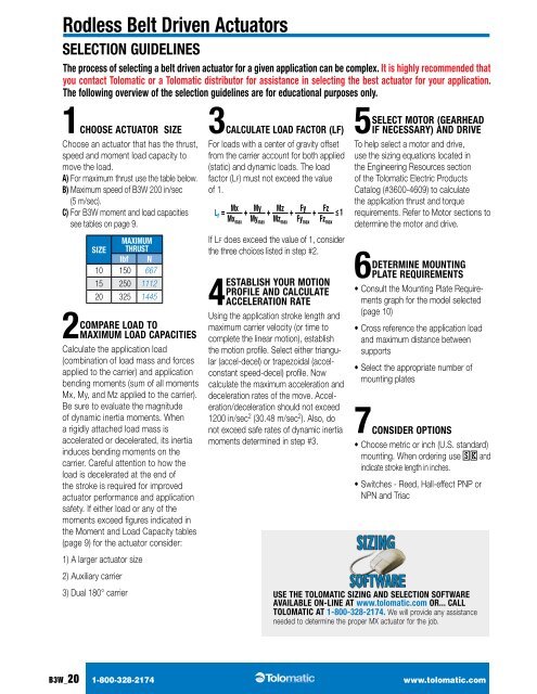
ABmxemxBb3sb3wtkstkbbcsslsICRIMAgswarsagsamrvmrsGEARBOXSwItCHRODLESS ACTUATORSROD STYLE ACTUATORSCONTROL SYSTEMS +Rodless <strong>Belt</strong> Driven Actu<strong>at</strong>orsSelection guidelinesThe process of selecting a belt driven <strong>actu<strong>at</strong>or</strong> for a given applic<strong>at</strong>ion can be complex. It is highly recommended th<strong>at</strong>you contact Tolom<strong>at</strong>ic or a Tolom<strong>at</strong>ic distributor for assistance in selecting <strong>the</strong> best <strong>actu<strong>at</strong>or</strong> for your applic<strong>at</strong>ion.The following overview of <strong>the</strong> selection guidelines <strong>are</strong> for educ<strong>at</strong>ional purposes only.1 CHOOSE ACTUATOR SIZEChoose an <strong>actu<strong>at</strong>or</strong> th<strong>at</strong> has <strong>the</strong> thrust,speed and moment load capacity tomove <strong>the</strong> load.A) For maximum thrust use <strong>the</strong> table below.B) Maximum speed of <strong>B3W</strong> 200 in/sec(5 m/sec).C) For <strong>B3W</strong> moment and load capacitiessee tables on page 9.MaximumSIZE thrustlbf N10 150 66715 250 111220 325 14452COMPARE LOAD TOMAXIMUM LOAD CAPACITIESCalcul<strong>at</strong>e <strong>the</strong> applic<strong>at</strong>ion load(combin<strong>at</strong>ion of load mass and forcesapplied to <strong>the</strong> carrier) and applic<strong>at</strong>ionbending moments (sum of all momentsMx, My, and Mz applied to <strong>the</strong> carrier).Be sure to evalu<strong>at</strong>e <strong>the</strong> magnitudeof dynamic inertia moments. Whena rigidly <strong>at</strong>tached load mass isacceler<strong>at</strong>ed or deceler<strong>at</strong>ed, its inertiainduces bending moments on <strong>the</strong>carrier. C<strong>are</strong>ful <strong>at</strong>tention to how <strong>the</strong>load is deceler<strong>at</strong>ed <strong>at</strong> <strong>the</strong> end of<strong>the</strong> stroke is required for improved<strong>actu<strong>at</strong>or</strong> performance and applic<strong>at</strong>ionsafety. If ei<strong>the</strong>r load or any of <strong>the</strong>moments exceed figures indic<strong>at</strong>ed in<strong>the</strong> Moment and <strong>Load</strong> Capacity tables(page 9) for <strong>the</strong> <strong>actu<strong>at</strong>or</strong> consider:1) A larger <strong>actu<strong>at</strong>or</strong> size2) Auxiliary carrier3) Dual 180° carrier3 CALCULATE LOAD FACTOR (LF)For loads with a center of gravity offsetfrom <strong>the</strong> carrier account for both applied(st<strong>at</strong>ic) and dynamic loads. The loadfactor (LF) must not exceed <strong>the</strong> valueof 1.LMxF+MyMymax=Mxmax+Mz+FyMzmax Fymax+Fz < 1Fz maxIf LF does exceed <strong>the</strong> value of 1, consider<strong>the</strong> three choices listed in step #2.4ESTABLISH YOUR MOTIONPROFILE AND CALCULATEAcceler<strong>at</strong>ion RATEUsing <strong>the</strong> applic<strong>at</strong>ion stroke length andmaximum carrier velocity (or time tocomplete <strong>the</strong> linear motion), establish<strong>the</strong> motion profile. Select ei<strong>the</strong>r triangular(accel-decel) or trapezoidal (accelconstantspeed-decel) profile. Nowcalcul<strong>at</strong>e <strong>the</strong> maximum acceler<strong>at</strong>ion anddeceler<strong>at</strong>ion r<strong>at</strong>es of <strong>the</strong> move. Acceler<strong>at</strong>ion/deceler<strong>at</strong>ionshould not exceed1200 in/sec 2 (30.48 m/sec 2 ). Also, donot exceed safe r<strong>at</strong>es of dynamic inertiamoments determined in step #3.5SELECT MOTOR (GEARHEADIF NECESSARY) AND DRIVETo help select a motor and drive,use <strong>the</strong> sizing equ<strong>at</strong>ions loc<strong>at</strong>ed in<strong>the</strong> Engineering Resources sectionof <strong>the</strong> Tolom<strong>at</strong>ic Electric ProductsC<strong>at</strong>alog (#3600-4609) to calcul<strong>at</strong>e<strong>the</strong> applic<strong>at</strong>ion thrust and torquerequirements. Refer to Motor sections todetermine <strong>the</strong> motor and drive.6DETERMINE MOUNTINGPLATE REQUIREMENTS• Consult <strong>the</strong> Mounting Pl<strong>at</strong>e Requirementsgraph for <strong>the</strong> model selected(page 10)• Cross reference <strong>the</strong> applic<strong>at</strong>ion loadand maximum distance betweensupports• Select <strong>the</strong> appropri<strong>at</strong>e number ofmounting pl<strong>at</strong>es7 CONSIDER OPTIONS• Choose metric or inch (U.S. standard)mounting. When ordering use SK andindic<strong>at</strong>e stroke length in inches.• Switches - Reed, Hall-effect PNP orNPN and TriacUSE <strong>the</strong> tolom<strong>at</strong>ic sizing and selection softw<strong>are</strong>available on-line <strong>at</strong> www.tolom<strong>at</strong>ic.com or... Calltolom<strong>at</strong>ic <strong>at</strong> 1-800-328-2174. We will provide any assistanceneeded to determine <strong>the</strong> proper MX <strong>actu<strong>at</strong>or</strong> for <strong>the</strong> job.C<strong>B3W</strong>_20 1-800-328-2174 www.tolom<strong>at</strong>ic.com


