

TOL-O-MATIC, INC. Parts Sheet - You are now at the Down-Load ...
TOL-O-MATIC, INC. Parts Sheet - You are now at the Down-Load ...
TOL-O-MATIC, INC. Parts Sheet - You are now at the Down-Load ...
- No tags were found...

You also want an ePaper? Increase the reach of your titles
YUMPU automatically turns print PDFs into web optimized ePapers that Google loves.
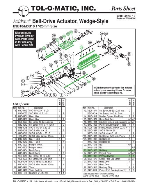
®<strong>TOL</strong>-O-<strong>MATIC</strong>,<strong>INC</strong>. <strong>Parts</strong> <strong>Sheet</strong>Axidyne ® Belt-Drive Actu<strong>at</strong>or, Wedge-StyleB3B10/M3B10 1"/25mm SizeDiscontinuedProduct Style orSize. <strong>Parts</strong> <strong>Sheet</strong>is for use onlywith Repair Kits54894544 4243 383736353431 32 33101315164817471 3 2 6 721201139401214412518 1946222326302450 493600-4123_12Replaced 3600-4086272928NOTE: Items shaded cannot be field installedwithout proper assembly fixtures. For repair,return cylinder to Tol-O-M<strong>at</strong>ic, Inc.List of <strong>Parts</strong>B3B10M3B10Item Part No. Description1. 3410-1413 SHCS #8-32 x 1.5 LG 24415-1063 SHCS M4 x 0.7 x 45 22. 3410-1401 Head, Idler 14410-1401 Head, Idler 13. 0905-1077 Set Screw #6-32 x .50 cup 20610-1212 Set Screw M4 x 0.7 x 12mm 24. 0915-1016 SHCS, #10-24 x .50 LG 24415-1016 SHCS, M5 x .8 x 16 25. 0915-1016 SHCS, #10-24 x .50 LG 41124-1034 SHCS, M5 x .8mm x 10mm 46. 3410-1013 Nut, T, BC3 44410-1013 Nut, T, BC3 47. 3410-9209 Bumper Mount 24410-9209 Bumper Mount 28. 3410-1404 Band Clamp 24410-1404 Band Clamp 29. 2002-1010 Set Screw, #8-32 x .19 47906-1029 Set Screw, M5-0.8 x 6mm 410. 0605-1046 SHCS, #8-32 x 0.38, BLK 44410-1077 SHCS, M5 x .8mm x 10mm 411. 3410-1411 Yoke 14410-1411 Yoke, (Metric) 112. 3410-1410 Shaft 3/8, x 1.313 long 1 1B3B10M3B10Item Part No. Description13. 1301-1174 Set Screw, #8-32 x 0.25, cup 20610-1046 Set Screw, M4-0.8 x 6mm 214. 3410-1419 Washer, Spacer, Idler Pulley 2 215. 3410-1424 Upper Dust Band A/R A/R16. 3410-1421 Belt, 5mm pitch, .5" wide, neoprene A/R A/R17. 3410-1406 Pulley, Idler, 5mm pitch 1" wide 1 118. 1001-1055 Bearing, Needle, .38 ID,.56 OD, .62 W 1 1*19. 0910-1357 SHCS, #4-40 x .50 84905-1012 SHCS, M3 x 0.5 x 12 8*20. 3410-1409 Belt Clamp, 5MM pitch 1" wide 2 2*21. 3410-1408 Belt Bracket 14410-1408 Belt Bracket 122. 3410-1013 Nut A/R4415-1013 Nut A/R23. 3410-1426 Rail Way A/R A/R24. 3410-1425 Magnet, Band A/R A/R25. 3410-1495 Machined Wedge 1 126. 0605-1079 Socket Head Cap Screw A/R A/R27. 3410-1403 Head, Drive 14410-1403 Head, Drive 128. 3410-1418 Retaining Ring 2 229. 3410-9151 Pulley, Shaft, Bearing Assembly 1 1*Also included in Belt Bracket AssemblyB3B10 = 3410-9350 M3B10 = 4410-9350<strong>TOL</strong>-O-<strong>MATIC</strong> • URL: http://www.tolom<strong>at</strong>ic.com • Email: help@tolom<strong>at</strong>ic.com • Fax: (763) 478-8080 • Toll Free: 1-800-328-2174
2– <strong>Parts</strong> Listing (Continued) B3B10, M3B10 <strong>Parts</strong> <strong>Sheet</strong> #3600-4123_1254894544433736353431 32 3310131516384817471 3 2 6 74221201139401214412518 1946222326302450 4927NOTE: Items shaded cannot be field installedwithout proper assembly fixtures. For repair,return cylinder to Tol-O-M<strong>at</strong>ic, Inc.Drawing repe<strong>at</strong>ed for reference2928B3B10M3B10Item Part No. Description30. 3410-1470 Tube, Machined 14410-1470 Tube, Machined 131. 0605-1079 SHCS, #4-40 x 0.25, BLK 44905-1005 SHCS, M3 x 0.5 x 6mm, BLK 432. 3410-2024 Cap, End, BC310 2 233. 3410-1024 Way, Carrier 2 234. 3410-1047 Upper Band Ramp 2 235. 0910-1357 SHCS, #4-40 x .5 24905-1012 SHCS, M3 x 0.5 x 8mm, BLK 236. 3410-1014 Ball Return 2 237. 3410-1510 Wiper 2 2*38. 0910-1166 SHCS, #8-32 x 0.75, 44415-1001 SHCS, M4 x 0.7 x10 4*Also included in Belt Bracket AssemblyB3B10 = 3410-9350 M3B10 = 4410-9350B3B10M3B10Item Part No. Description39. 3410-1009 Ball 116 11640. 3410-1019 Ball Return Tube 2 241. 3410-2022 Cover, Carrier 1 142. 3410-2021 Machined Carrier 14410-1235 Machined Carrier 143. 3410-1015 Right Ball Race 2 244. 3410-1032 Left Ball Race 2 245. 3410-1413 SHCS, #8-32 x 1.5 44515-1063 SHCS, M4 x .7 x 38mm 4*46. 3415-1218 Magnet 2 247. 3415-1218 Cap, Plug, .500 2 248. 3410-1079 PLT, Ball Return 2 249. 3410-1540 Cover 1 150. 0910-1081 Button Head Cap Screw 45605-1016 Button Head Cap Screw 4<strong>TOL</strong>-O-<strong>MATIC</strong> • URL: http://www.tolom<strong>at</strong>ic.com • Email: help@tolom<strong>at</strong>ic.com • Fax: (763) 478-8080 • Toll Free: 1-800-328-2174
<strong>Parts</strong> <strong>Sheet</strong> #3600-4123_12 B3B10, M3B10 Install<strong>at</strong>ion & Maintenance Instructions – 3GENERAL DISASSEMBLY INSTRUCTIONSBegin with a clean work <strong>are</strong>a. Be sure all replacement parts <strong>are</strong> present andhave no visual damage or defects. The following tools <strong>are</strong> recommended forproper disassembly and assembly (exact wrench sizes will vary dependingon actu<strong>at</strong>or size)Allen wrench set /Internal retaining ring pliers / Rubber hammer /Loctite® #2421. Remove any motor mounting hardw<strong>are</strong> and/or adapter pl<strong>at</strong>es.2. Release carrier assembly:Remove screws (31) from end caps (32) and remove end caps. Removecarrier cover (41). Loosen and remove dust band clamp (8) on idler anddrive head by removing SHCS (10). Remove <strong>the</strong> dust band (15).Remove 4 SHCS’s (38) th<strong>at</strong> hold <strong>the</strong> carrier (42) to <strong>the</strong> belt bracket (21).3. Remove idler headLoosen <strong>the</strong> two set screws (3). Remove 2 SHCS (1) in <strong>the</strong> idler headth<strong>at</strong> hold <strong>the</strong> tensioning yoke in. Remove 2 SHCS (45) th<strong>at</strong> hold head tobottom of tube. Loosen SHCS (5) th<strong>at</strong> hold head to top of tube. Removehead.Loosen 2 sets screws (13) in yoke th<strong>at</strong> hold shaft in. Remove shaft fromyoke.4. Remove beltRemove SHCS (19) on both belt clamps (20) of belt bracket (21)5. Remove drive headRemove 2 SHCS (45) th<strong>at</strong> hold <strong>the</strong> head to <strong>the</strong> bottom of <strong>the</strong> tube.Loosen SHCS (5) th<strong>at</strong> hold <strong>the</strong> head to <strong>the</strong> top of <strong>the</strong> tube. Removehead. Pull belt through actu<strong>at</strong>or and head.6. Optional removal of drive pulley/shaft (29) from drive head.Note: Do not remove carrier (42) from rail system.Balls contained in rail way will fall out.GENERAL ASSEMBLY INSTRUCTIONSAny time SHCS <strong>are</strong> being installed, apply Loctite #242 to <strong>the</strong> threads.1. If drive pulley/shaft (29) was removed. Fold belt in half (teeth facing eacho<strong>the</strong>r) and slip loop end into drive head.Wrap belt in a loop and insert it into drive head. Teeth on belt to be facingeach o<strong>the</strong>r.Slide pulley/shaft (29) into drive head. Note: press shaft in straight aspossible. Make sure it is all <strong>the</strong> way against <strong>the</strong> retaining ring on<strong>the</strong> o<strong>the</strong>r side of <strong>the</strong> head. Install retaining ring into groove in head.2. Mount drive head to actu<strong>at</strong>or:Slide belt through tube and slide drive head onto tube using T-nuts as aguide. Install 2 SHCS (45) to hold head on bottom of tube. Tighten bothSHCS (5) on top head.A. Direct Drive Option: (See drawing on page 5) Attach motor spacer (1)to actu<strong>at</strong>or with fasteners (2). Attach coupler (3) to motor shaft. Slidemotor/coupler into motor spacer (1). Through alignment hole in motorspacer, fasten coupler to shaft with allen wrench.3. Mount idler head to actu<strong>at</strong>or:Attach <strong>the</strong> belt (16) to <strong>the</strong> belt bracket (21) with <strong>the</strong> belt clamp (20) andSHCS (19). Place <strong>the</strong> idler pulley (17) inside <strong>the</strong> <strong>the</strong> belt loop. Install <strong>the</strong>idler shaft through <strong>the</strong> yoke (11) and <strong>the</strong> two spacer washers (14). Slideidler head onto tube using T-nuts as a guide. Install 2 SHCS (45) to holdhead on bottom of tube. Tighten both SHCS (5) on top head. Install 2SHCS (1) into yoke. Tighten both equal to achieve <strong>the</strong> desired belt tension.Note: Over tensioning of belt can cause it to stretch prem<strong>at</strong>urely.Tighten both set screws (3).4. Lubric<strong>at</strong>e ballways:Before installing <strong>the</strong> top dust band (15), lubric<strong>at</strong>e <strong>the</strong> ballways withMobil HP Grease.5. Attach Carrier to Belt Bracket:Mount carrier (42) to belt bracket (21) with 4 SHCS (38).6. Trim and Install Dust Band:Install dust band (15) over carrier (42) centering it along <strong>the</strong> length of <strong>the</strong>actu<strong>at</strong>or. With a tin snips, cut band down 1/16" from <strong>the</strong> heads. Slidecarrier cover (41) into slots on top of carrier. Install carrier endcaps (32)with SHCS. Loosely install band clamps (8) onto each head withSHCS (10). Slide carrier to one end of actu<strong>at</strong>or, and tighten SHCS (10).Slide carrier to o<strong>the</strong>r end of actu<strong>at</strong>or and repe<strong>at</strong>.7. Re-<strong>at</strong>tach any motor adapter pl<strong>at</strong>es and/or hardw<strong>are</strong> with actu<strong>at</strong>or.REVERSE PARALLEL DISASSEMBLY INSTRUCTIONS:1. Remove End Caps (14). Release tension on belt by breaking loose<strong>the</strong> motor fasteners (17).2. Remove RP Cover (2).3. Remove both drive pulley (7) and driven pulley(5) from <strong>the</strong>ir respectiveshafts. The belt(3) will come off with <strong>the</strong> pulley’s.4. Remove motor fasteners (17) from <strong>the</strong> motor pl<strong>at</strong>e (9), to remove<strong>the</strong> motor from <strong>the</strong> RP case.5. Remove <strong>the</strong> RP case (12) from <strong>the</strong> head by removing fasteners (10).REVERSE PARALLEL ASSEMBLY INSTRUCTIONS:*Apply Loctite #242 to all fasteners upon install<strong>at</strong>ion1. Install RP case (12) to <strong>the</strong> head with cap screws (10).2.. Install <strong>the</strong> motor to <strong>the</strong> RP case with fasteners (17). Do not tighten<strong>the</strong> fasteners <strong>at</strong> this time.3. Loc<strong>at</strong>e <strong>the</strong> belt (3) over <strong>the</strong> pulleys and slide <strong>the</strong> drive (7) and driven(5) pulleys over <strong>the</strong>ir respective shafts. Tighten each pulley to it’sshaft with ei<strong>the</strong>r set screws, trantorque or collar clamp. If trantorque,utilize torque wrench to apply appropri<strong>at</strong>e torque. 1/2" hex on trantorqueapply 75 in-lbs. 5/8" hex on trantorque apply 100 in-lbs.4. Verify th<strong>at</strong> <strong>the</strong>re is clearance between <strong>the</strong> inside of <strong>the</strong> RP case andeach pulley. Verify th<strong>at</strong> <strong>the</strong> pulleys <strong>are</strong> aligned to each o<strong>the</strong>r.5. Position <strong>the</strong> cover (2) in m<strong>at</strong>ing slot of <strong>the</strong> RP case and install <strong>the</strong>SHCS (1) to hold in place.6. Tension <strong>the</strong> belt by pulling <strong>the</strong> motor away from <strong>the</strong> drive shaft with<strong>the</strong> appropri<strong>at</strong>e force in <strong>the</strong> chart below. Tighten <strong>the</strong> motor fastenerswhile this force is applied to <strong>the</strong> motor.Motor Frame Tension ForceMRB23, MRS23 10 lbsMRV23, MRS34 20 lbsMRV34, MRB34 30 lbsMRV5140 lbs7. Install both end caps (14) with <strong>the</strong> screws (13) to finalize assembly.<strong>TOL</strong>-O-<strong>MATIC</strong> • URL: http://www.tolom<strong>at</strong>ic.com • Email: help@tolom<strong>at</strong>ic.com • Fax: (763) 478-8080 • Toll Free: 1-800-328-2174
4– Reduction Drive Option B3B10, M3B10 <strong>Parts</strong> <strong>Sheet</strong> #3600-4123_123:1 Reduction Drive131516 171236127 8 9 114510143:1 Reduction Drive <strong>Parts</strong> ListingBCB10MCB10MRV21,22,23,24MRS231,232,MRB21MRV31,32,33,MRB31,32MRS341,342,343MRB41,42MRV51MRV21,22,23,24MRS231,232,MRB21MRV31,32,33,MRB31,32MRS341,342,343MRB41,42MRV51Item Part No. Description1 3420-1641 SHCS, M6 X 1.0, 60 MM LONG, LOW HEAD, SST 1 1 1 1 1 1 1 1 1 1 1 12 3420-1613 COVER, B3B-23 FRAME 1 1 1 13420-1614 COVER, B3B-34 FRAME 1 1 1 13420-1615 COVER, B3B-40 FRAME 1 13420-1616 COVER, B3B-51 FRAME 1 13 3415-1441 TIMING BELT, 425-5M-19 1 1 1 1 1 1 1 13410-1441 TIMING BELT, 425-5M-09 1 13415-1453 TIMING BELT, 535-5M-19 1 14 0520-1067 CLAMP COLLAR, Ø.688 1 1 1 1 1 1 1 1 1 1 1 15 3415-1439 PULLEY, 60 TEETH, 19MM WIDTH 1 1 1 1 1 1 1 1 1 13410-1439 PULLEY, 60 TEETH, 9MM WIDTH 1 16 0610-1190 SET SCREW, 6-32, .188 LONG 2 2 2 2 2 2 2 27 3415-1438 PULLEY, 20 TEETH, 19 MM WIDTH 1 1 1 13420-9191 PULLEY, 20 TEETH, 9 MM WIDTH 1 13415-1445 PULLEY, 20 TEETH, 19 MM WIDTH 1 13420-1438 PULLEY, 20 TEETH, 19 MM WIDTH 1 1 1 18 0510-1111 TRANTORQ, Ø.250 1 10515-1181 TRANTORQ, Ø.375 1 19 0602-1057 PLATE, MOTOR, 34 FRAME 1 1 1 13420-1611 PLATE, MOTOR, 40 FRAME 1 13420-1625 PLATE, MOTOR, 51 FRAME 1 110 3410-1229 BHCS, TORX, #10-24 x .50 4 4 4 4 4 43420-1645 SHCS, M5 X 0.8, 16 MM LONG, LOW HEAD 4 4 4 4 4 411 0603-2089 NUT, HEX, M5 X 0.8 4 4 4 412 3420-1603 HOUSING, B3B-23 FRAME 1 1 1 13420-1604 HOUSING, B3B-34 FRAME 1 1 1 13420-1605 HOUSING, B3B-40 FRAME 1 13420-1606 HOUSING, B3B-51 FRAME 1 113 0601-1625 SCREW, #6 X .25, SELF-TAPPING, SST 8 8 8 8 8 8 8 8 8 8 8 814 3420-1602 END CAP 2 2 2 2 2 2 2 2 2 2 2 215 2212-1010 SFHCS, 1/4-20, .75 LONG 4 416 3420-1612 PLATE, ADAPTER, 40 FRAME 1 117 2212-1098 SHCS, M5 X 0.8, 20 MM LONG, SST 4 42212-1096 SHCS, M5 X 0.8, 12 MM LONG, SST 4 42212-1099 SHCS, M5 X 0.8, 25 MM LONG, SST 4 4 4 4 4 43420-1638 SHCS, M8 X 1.25, 35 MM LONG, SST 4 4<strong>TOL</strong>-O-<strong>MATIC</strong> • URL: http://www.tolom<strong>at</strong>ic.com • Email: help@tolom<strong>at</strong>ic.com • Fax: (763) 478-8080 • Toll Free: 1-800-328-2174
<strong>Parts</strong> <strong>Sheet</strong> #3600-4123_12 B3B10, M3B10 Direct Drive and Gearhead Option – 51Gearhead6Direct DriveNOTE:For BeltTensioning Kitplease refer topart sheet3600-460223Direct Drive <strong>Parts</strong> ListingMRV23_MRS34XMRB34XMRV34XMRB40XMRS23_, MRV 23_, MRB23 W/GHJ20, GHJ21, GHK20MRV34_ W/GHJ30MRB21 \ MRS23XMRB34_, MR334 W/GHJ30, GHJ31, GHK30MRV34_ W/GHJ31Item Part No. Description1. 3410-1451 Motor Adapter, Mach, B3B 13410-1452 Motor Adapter, Mach, B3B 1 13410-1453 Motor Adapter, Mach, B3B 1 13410-1457 Motor Adapter, Mach, B3B 13410-1455 Motor Adapter, Mach, B3B 1 1 13410-1456 Motor Adapter, Mach, B3B 1 12. 0910-1314 SHCS, #10-24 x 0.75, BLK 4 4 4 4 4 4 4 4 4 43. 3600-9253 Coupler, Guardian 1 13600-6163 Coupler, Zero-Max 13600-6174 Coupler, Zero-Max 13600-6175 Coupler, Zero-Max 13420-9041 Coupler, Guardian 13600-6176 Coupler, Zero-Max 13600-6177 Coupler, Zero-Max 1 13600-9252 Coupler, Guardian 13600-9218 Coupler, Guardian 14. 3410-1445 Motor Adapter Pl<strong>at</strong>e, MRB40X 15. 3420-1223 SFCHS, 1/4-20 x 1.00 LG 46. 4415-1020* SHCS, M5 x .8 x 20, BLK 4 4 4 4 4 4 4 4 4 41024-7711 SHCS, #10-24 x .88, BLK 4 4 4 4 4 4 4 4 4 4* Used on <strong>the</strong> M3B10 actu<strong>at</strong>or.5Motor<strong>TOL</strong>-O-<strong>MATIC</strong> • URL: http://www.tolom<strong>at</strong>ic.com • Email: help@tolom<strong>at</strong>ic.com • Fax: (763) 478-8080 • Toll Free: 1-800-328-21744
6– Dual 180° Carrier Option B3B10, M3B10 <strong>Parts</strong> <strong>Sheet</strong> #3600-4123_125455225760562351505253591558243643 443742394041333231343548Dual 180°ItemB3BD10 M3BD10 OptionPart No. Part No.DescriptionQTY.15. 3410-1239 3410-1239 Dust Band 122. 3410-1013 4410-1013 Nut 423. 3410-1426 3410-1426 Rail Way 224. 3410-1240 3410-1263 Band Magnet 231. 0605-1079 4905-1005 Socket Head Cap Screw 432. 3410-2024 3410-2024 End Cap 233. 3410-1023 3410-1023 Carrier Way 234. 3410-1047 3410-1047 Upper Band Ramp 235. 0910-1357 4905-1012 Socket Head Cap Screw 236. 3410-1014 3410-1014 Ball Return 237. 3410-1510 3410-1510 Wiper 239. 3410-1009 3410-1009 Ball 11240. 3410-1019 3410-1019 Ball Return Tube 241. 3410-2022 3410-2022 Carrier Cover 142. 3410-2021 4410-1235 Machined Carrier 1Dual 180°ItemB3BD10 M3BD10 OptionPart No. Part No.DescriptionQTY.43. 3410-1015 3410-1015 Right Ball Race 244. 3410-1016 3410-1016 Left Ball Race 248. 3410-1079 3410-1079 PLT, Ball Return 250. 3410-1049 4410-1049 Pl<strong>at</strong>e, Conn., Dual Carrier 251. 2317-1014 4415-1000 Socket Head Cap Screw 852. 3410-1446 4410-1446 Pl<strong>at</strong>e, Dual Carrier 153. 2317-1014 4415-1000 Socket Head Cap Screw 854. 0915-1016 4415-1022 Socket Head Cap Screw 455. 3410-1053 3410-1053 Tube Support 156. 3410-1427 3410-1427 Machined Rail 257. 3410-1008 4410-1008 Rail Nut AR58. 3410-1229 3410-1229 Button Head Cap Screw AR59. 3410-1048 3410-1048 Washer AR60. 3410-1448 4410-1148 Dual 180° Band Clamp 2<strong>TOL</strong>-O-<strong>MATIC</strong> • URL: http://www.tolom<strong>at</strong>ic.com • Email: help@tolom<strong>at</strong>ic.com • Fax: (763) 478-8080 • Toll Free: 1-800-328-2174
<strong>Parts</strong> <strong>Sheet</strong> #3600-4123_12 B3B10, M3B10 Options – 7SWITCH KITTUBE SUPPORT KIT1 29108MOUNTINGPLATES3456Optional Accessories <strong>Parts</strong> ListingSWITCH KITSwitch Kit number (Hardw<strong>are</strong> & switch)Description Part Number (SWB3S10_ _) Description1. Switch Only, Reed, Form C, 5m 3600-9084 BT Form C, 5m leadSwitch Only, Reed, Form C, Male Conn. 3600-9085 BM Form C, 5m QD leadSwitch Only, Reed, Form A, 5m 3600-9082 RT Form A, 5m leadSwitch Only, Reed, Form A, Male Conn. 3600-9083 RM Form A, 5m QD leadSwitch Only, Triac, 5m 3600-9086 CT Triac switch, 5m leadSwitch Only, Triac, Male Conn. 3600-9087 CM Triac switch, 5m QD leadSwitch Only, Hall-effect, Sinking, 5m 3600-9090 KT Hall-effect, Sinking switch, 5m leadSwitch Only, Hall-effect, Sinking, Male Conn. 3600-9091 KM Hall-effect, Sinking switch, 5m QD leadSwitch Only, Hall-effect, Sourcing, 5m 3600-9088 TT Hall-effect, Sourcing switch, 5m leadSwitch Only, Hall-effect, Sourcing, Male Conn. 3600-9089 TM Hall-effect, Sourcing switch, 5m QD leadConnector (Female) 5 meter lead 2503-1025Item Part No. Description Qty.2. 3410-9999 Switch Hardw<strong>are</strong> Kit A/RTUBE SUPPORT KIT3. 3410-1012 SHCS, #10-24 x 0.44 44410-1077 SHCS, M5 x 0.8mm x 10mm 44. 2006-1063 SFHCS, #10-24 x 0.38 44410-1016 SFHCS, M5 x 0.8 x 10 45. 3410-1013 B3C310 Nut 84410-1013 BC3M10 Metric Nut 86. 3410-1044 BC310 Tube Support 2MOUNTING PLATES8. 0915-1016 SFHCS, #10-24 x 0.50 44415-1016 SFHCS, M5 x 8 x 16mm 49. 3410-1332 Mounting Pl<strong>at</strong>e, B3S, 0.50 210. 3410-1013 Nut 44410-1013 Nut, Metric 42. Switches. Secure Switch (1) tomagnet side of Tube with SwitchClamp (2) and Set Screw.3. SWITCHESREED SWITCHESNOTE: Form A Reed Switches should not beused in TTL logic circuits. A voltage dropcaused by <strong>the</strong> L.E.D. indic<strong>at</strong>or will result. Forapplic<strong>at</strong>ions where TTL circuits <strong>are</strong> used,please contact <strong>the</strong> factory.WARNING: An ohmmeter is recommendedfor testing Reed Switches. NEVER use anincandescent light bulb as a high current rushmay damage <strong>the</strong> switch.OPTIONAL ACCESSORY ASSEMBLYINSTRUCTIONS1. TUBE SUPPORTS. Four T-Nuts (5) <strong>are</strong>required on each side of <strong>the</strong> Tube (30),two T-Nuts on bottom of Tube and twoin lower slots on tube sides. TubeSupports should be secured <strong>at</strong> <strong>the</strong>required distances determined for <strong>the</strong>applic<strong>at</strong>ion to prevent Tube deflection.Apply Loctite #242 to Screws (4) andsecure Tube Supports (6) to Tube aligningholes in T-Nuts with holes in TubeSupports.TO ORDER RETROFIT KITS:SW <strong>the</strong>n <strong>the</strong> model number and base size,and code for type of switch needed:EXAMPLE: SWB3B10RMWhere SW is <strong>the</strong> switch, B3B10 is <strong>the</strong> 1inch size, and RU is a Form A ReedSwitch with quick disconnect and 5 meterleadAll switch kits include 1 switch and mountinghardw<strong>are</strong>Reed and TRIAC switches <strong>are</strong> only recommendedfor signalling position, not directlypowering solenoids. For shifting a solenoid, <strong>are</strong>lay or resistor is recommended between itand <strong>the</strong> Reed Switch. Switch r<strong>at</strong>ings must notbe exceeded <strong>at</strong> any time.<strong>TOL</strong>-O-<strong>MATIC</strong> • URL: http://www.tolom<strong>at</strong>ic.com • Email: help@tolom<strong>at</strong>ic.com • Fax: (763) 478-8080 • Toll Free: 1-800-328-2174
8– Switches B3B10, M3B10 <strong>Parts</strong> <strong>Sheet</strong> #3600-4123_12Universal Switch Wiring Diagrams and Label Color Coding(+)(-)OR(+)(-)LOADLOADBROWN(+)BLUE(-)BROWN(+)BLUE(-)REEDSWITCHREEDSWITCHREED SWITCH FORM ALABEL COLOR: RED10VA MAX.200 Vdc500mA Max. CurrentCOMMONNORMALLY CLOSEDNORMALLY OPENBROWNBLACKBLUEREED SWITCH FORM CLABEL COLOR: YELLOW120 Vdc/120 Vac MAX.250mA Max. CurrentREEDSWITCH120VacMax.BLUEMOVTRIACSWITCHBROWNACCOMLOADINPUTTRIAC SWITCHLABEL COLOR: BLUEMax. 1Amp. Cont. Current @ 86°FMax. .5Amp. Cont. Current @ 140°FPeak surge current 10Amp.HALL-EFFECTSOURCINGSWITCHBROWN(+)BLACKBLUE (-)(+)(-)LOADHALL-EFFECT SWITCH(SOURCING)LABEL COLOR: WHITEInput Voltage:5-25 VDC onlyOutput Current: 200 mA Max.HALL-EFFECTSINKINGSWITCHBROWN(+)BLACKBLUE (-)(+)(-)LOADHALL-EFFECT SWITCH(SINKING)LABEL COLOR: GREENInput Voltage:5-25 VDC onlyOutput Current: 200 mA Max.BLUEBLACKBROWNQUICK-DISCONNECT(Applies to all switch types)An Important Note Regarding FieldRetrofit of Quick-DisconnectCouplers:If replacing a Quick-Disconnect switchmanufactured before 7-1-97 it will alsobe necessary to replace or rewire <strong>the</strong>female-end coupler with <strong>the</strong> in-line splice2503-1025 Female Connector 5MSWITCH TYPE CODEBTBMRTRMCT(Form C Reed Switch with 5-meter lead)(Form C Reed Switch with 5-meter lead and QD)(Form A Reed Switch with 5-meter lead)(Form A Reed Switch with 5-meter lead and QD)(TRIAC Switch with 5-meter lead)CMKTKMTTTM(TRIAC Switch with 5-meter lead and QD)(Hall-effect Switch (Sinking) 5-meter lead)(Hall-effect Switch (Sinking) 5-meter lead and QD)(Hall-effect Switch (Sourcing) 5-meter lead)(Hall-effect Switch (Sourcing) 5-meter lead and QD)Axidyne® is a registered trademark of Tol-O-M<strong>at</strong>ic, Inc.Loctite® is a registered trademark of <strong>the</strong> Loctite Corpor<strong>at</strong>ion, www.loctite.com<strong>TOL</strong>-O-<strong>MATIC</strong>, <strong>INC</strong>.3800 County Road 116, Hamel, MN 55340http://www.Tolom<strong>at</strong>ic.com • Email: Help@Tolom<strong>at</strong>ic.comPhone: (763) 478-8000 • Fax: (763) 478-8080 • Toll Free: 1-800-328-2174Inform<strong>at</strong>ion furnished is believed to be accur<strong>at</strong>eand reliable. However, Tol-O-M<strong>at</strong>ic assumes noresponsibility for its use or for any errors th<strong>at</strong> mayappear in this document. Tol-O-M<strong>at</strong>ic reserves <strong>the</strong>right to change <strong>the</strong> design or oper<strong>at</strong>ion of <strong>the</strong>equipment described herein and any associ<strong>at</strong>edmotion products without notice. Inform<strong>at</strong>ion inthis document is subject to change without notice.© 2006 <strong>TOL</strong>-O-<strong>MATIC</strong>, <strong>INC</strong>.


