

TOL-O-MATIC, INC. Parts Sheet - You are now at the Down-Load ...
TOL-O-MATIC, INC. Parts Sheet - You are now at the Down-Load ...
TOL-O-MATIC, INC. Parts Sheet - You are now at the Down-Load ...
- No tags were found...

Create successful ePaper yourself
Turn your PDF publications into a flip-book with our unique Google optimized e-Paper software.
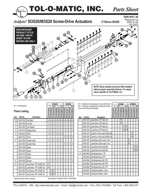
®<strong>TOL</strong>-O-<strong>MATIC</strong>, <strong>INC</strong>.<strong>Parts</strong> <strong>Sheet</strong>Axidyne ® B3S20/M3S20 Screw-Drive Actu<strong>at</strong>ors2"/50mm BORE3600-4043_08Replaced by3600-413005-2002DISCONTINUEDPRODUCT STYLEOR SIZE. PARTSSHEET IS FORREPAIR USE ONLY.29282726253130443233343536372418173819201232122678910 11 12391314 15 16NOTE: Items shaded cannot be field installedwithout proper assembly fixtures. For repair,return cylinder to Tol-O-M<strong>at</strong>ic, Inc.2 3 4 5A/R = As Required<strong>Parts</strong> ListingItem Part No. Description1*§ 3420-1239 Dust Band A/R A/R A/R A/R A/R A/R A/R A/R A/R A/R2 3420-1206 Lock Nut 2 2 2 2 2 2 2 2 2 23 3420-1205 Lock Washer 2 2 2 2 2 2 2 2 2 24 2100-1010 Retaining Ring 2 2 2 2 2 2 2 2 2 25 1309-2020 SHCS 8 8 8 8 8 8 – – – –4925-1033 SHCS – – – – – – 8 8 8 86 3420-1200 Actu<strong>at</strong>or Head 2 2 2 2 2 2 – – – –4420-1200 Actu<strong>at</strong>or Head – – – – – – 2 2 2 27 3420-1208 Spacer – – – – 1 1 – – – –3420-1209 Spacer 1 1 – – – – 1 1 – –3420-1210 Spacer 1 1 1 1 1 1 1 1 1 14420-1210 Spacer – – – – – – – – 1 18 2332-1006 Bumper 2 2 2 2 2 2 2 2 2 29* 3420-1201 Lead Screw, 1TPI, ACME, Std ST – – – – – – – – –3420-1250 Lead Screw, 1TPI, ACME, Ext OP – – – – – – – – –3420-1202 Lead Screw, 2TPI, ACME, Std – ST ST – – – – – – –3420-1251 Lead Screw, 2TPI, ACME, Ext – OP OP – – – – – – –* Specify stroke when ordering. § Available in Repair Kit No. 3420-9049.B3S20 M3S20 ST = Standard Configur<strong>at</strong>ion (Used with LMI) B3S20 M3S20OP = Optional Configur<strong>at</strong>ion, Extended Shaft(Used with Reverse Parallel)B3S20SN01B3S20SN02B3S20SNA02B3S20BN02B3S20BN05B3S20BNL05M3S20SN25M3S20SN12M3S20BN05M3S20BNL05B3S20SN01B3S20SN02B3S20SNA02B3S20BN02B3S20BN05B3S20BNL05M3S20SN25M3S20SN12M3S20BN05M3S20BNL05Item Part No. Description9* 3420-1203 Lead Screw, 2TPI, Ball, Std – – – ST – – – – – –3420-1252 Lead Screw, 2TPI, Ball, Ext – – – OP – – – – – –3420-1204 Lead Screw, 5TPI, Ball, Std – – – – ST ST – – – –3420-1253 Lead Screw, 5TPI, Ball, Ext – – – – OP OP – – – –4420-1201 Lead Scw, 12mm Lead, ACME, Std – – – – – – – ST – –4420-1250 Lead Scw, 12mm Lead, ACME, Ext – – – – – – – OP – –4420-1202 Lead Screw, 25mm Lead, V, Std – – – – – – ST – – –4420-1251 Lead Screw, 25mm Lead, V, Ext – – – – – – OP – – –4420-1203 Lead Screw, 5mm Lead, Ball – – – – – – – – ST ST4420-1252 Lead Screw, 5mm Lead, Ball – – – – – – – – OP OP10 3420-9062 Nut Bracket Assy, 1 TPI 1 – – – – – – – – –3420-9063 Nut Bracket Assy, 2TPI – 1 – – – – – – – –3420-9064 Nut Bracket Assy, BN, 2TPI – – – 1 – – – – – –3420-9065 Nut Bracket Assy, BN, 5TPI – – – – 1 1 – – – –3420-9066 Nut Bracket Assy, AB, 2TPI – – 1 – – – – – – –4420-9027 Nut Bracket (Metric), 12mm – – – – – – – 1 – –4420-9028 Nut Bracket (Metric), 25mm – – – – – – 1 – – –<strong>TOL</strong>-O-<strong>MATIC</strong> • URL: http://www.tolom<strong>at</strong>ic.com • Email: help@tolom<strong>at</strong>ic.com • Fax: (763) 478-8080 • Toll Free: 1-800-328-2174
2 – <strong>Parts</strong> Listing B3S20, M3S20 <strong>Parts</strong> <strong>Sheet</strong> #3600-4043_0829282726253130443233343536372418173819201232122678910 11 12391314 15 16NOTE: Items shaded cannot be field installedwithout proper assembly fixtures. For repair,return cylinder to Tol-O-M<strong>at</strong>ic, Inc.2 3 4 5Drawing repe<strong>at</strong>ed for referenceA/R = As RequiredB3S20M3S20B3S20M3S20B3S20SN01B3S20SN02B3S20SNA02B3S20BN02B3S20BN05B3S20BNL05M3S20SN25M3S20SN12M3S20BN05M3S20BNL05Item Part No. Description Item Part No. Description10 4420-9029 Nut Bracket (Metric), 5mm – – – – – – – – 1 111 3420-1013 Nut 4 4 4 4 4 4 – – – –4420-1013 Nut – – – – – – 4 4 4 412 3420-1241 Rail Way 2 2 2 2 2 2 2 2 2 213 3420-1240 Band Magnet 2 2 2 2 2 2 2 2 2 214 3420-1242 Machined Rail 2 2 2 2 2 2 2 2 2 215 3420-1008 Rail Nut A/R A/R A/R A/R A/R A/R – – – –4420-1008 Rail Nut – – – – – – A/R AR A/R A/R16 3420-1013 Nut A/R A/R A/R A/R A/R A/R – – – –4420-1013 Nut – – – – – – A/R AR A/R A/R18 0802-1252 Socket Head Cap Screw A/R A/R A/R A/R A/R A/R – – – –4415-1018 Socket Head Cap Screw – – – – – – A/R AR A/R A/R19 3415-1320 Sleeve BRG FLG 2 2 – – – – – 2 – –20 3420-1222 Contact Bearing 2 2 2 2 2 2 2 2 2 221 3420-1024 Carrier Way 2 2 2 2 2 2 2 2 2 222 3420-1219 Upper Clamp 2 2 2 2 2 2 – – – –4420-1219 Upper Clamp – – – – – – 2 2 2 223 3415-1455 Set Screw 4 4 4 4 4 4 – – – –4410-1017 Set Screw – – – – – – 4 4 4 424 3420-1221 Machined Tube 1 1 1 1 1 1 – – – –4420-1221 Machined Tube – – – – – – 1 1 1 1* Specify stroke when ordering. § Available in Repair Kit No. 3420-9049.B3S20SN01B3S20SN02B3S20SNA02B3S20BN02B3S20BN05B3S20BNL05M3S20SN25M3S20SN12M3S20BN05M3S20BNL0525 3420-1047 Upper Band Ramp 2 2 2 2 2 2 2 2 2 226 1085-1075 Socket Head Cap Screw 2 2 2 2 2 2 – – – –0610-1033 Socket Head Cap Screw – – – – – – 2 2 2 227 3420-1014 Ball Return 2 2 2 2 2 2 2 2 2 228 3420-1015 Right Ball Race 2 2 2 2 2 2 2 2 2 229 3420-1032 Left Ball Race 2 2 2 2 2 2 2 2 2 230§ 3420-1025 Wiper 2 2 2 2 2 2 2 2 2 231 3420-2021 Machined Carrier 1 1 1 1 1 1 – – – –4420-1235 Machined Carrier – – – – – – 1 1 1 132 3420-1223 Fl<strong>at</strong>head Cap Screw 3 3 3 3 3 3 – – – –4420-1011 Socket Head Cap Screw – – – – – – 3 3 3 333 3420-1009 Ball 92 92 92 92 92 92 92 92 92 9234 3420-1019 Ball Return Tube 2 2 2 2 2 2 2 2 2 235§ 3420-2022 Carrier Cover 1 1 1 1 1 1 1 1 1 136§ 3420-2024 End Cap 2 2 2 2 2 2 2 2 2 237 0605-1046 Socket Head Cap Screw 4 4 4 4 4 4 – – – –4415-1001 Socket Head Cap Screw – – – – – – 4 4 4 438 3420-9054 Head End Kit 1 1 1 1 1 1 – – – –4420-9054 Head End Kit – – – – – – 1 1 1 139 2406-1008 Magnet 2 2 2 2 2 2 2 2 2 244 3420-1069 PLT Ball Return 2 2 2 2 2 2 2 2 2 2<strong>TOL</strong>-O-<strong>MATIC</strong> • URL: http://www.tolom<strong>at</strong>ic.com • Email: help@tolom<strong>at</strong>ic.com • Fax: (763) 478-8080 • Toll Free: 1-800-328-2174
<strong>Parts</strong> <strong>Sheet</strong> #3600-4043_08 B3S20, M3S20 Dual 180° Option – 354625561562524195150525357605925840233435 363233312827422643393841<strong>Parts</strong> ListingB3S20DItemPart No.M3S20DPart No.Description QTY.2. 3420-1028 3420-1028 Dust Band 119. 3420-1023 3420-1023 Rail Way 223. 3420-1022 3420-1022 Band Magnet 224. 3420-1020 3420-1020 Machined Rail 225. 3420-1008 4420-1008 Rail Nut AR26. 3420-2024 3420-2024 End Cap 227. 3420-2022 3420-2022 Carrier Cover 128. 3420-1019 3420-1019 Ball Return Tube 231. 3420-1009 3420-1009 Ball 9232. 3420-1025 3420-1025 Wiper 233. 3420-2021 4420-1235 Machined Carrier 134. 3420-1014 3420-1014 Ball Return 235. 3420-1015 3420-1015 Right Ball Race 236. 3420-1032 3420-1032 Left Ball Race 238. 1085-1075 0610-1033 Socket Head Cap Screw 239. 3415-1047 3415-1047 Upper Band Ramp 240. 3420-1077 4415-1018 Socket Head Cap Screw ARItemB3S20D M3S20DPart No. Part No.Description QTY.41. 3420-1069 3420-1069 PLT Ball Return 242. 3420-1024 3420-1024 Carrier Way 243. 0605-1046 4415-1001 Socket Head Cap Screw 450. 3420-1049 4420-1049 Pl<strong>at</strong>e, Conn., Dual Carrier 251. 0920-1093 4415-1019 Socket Head Cap Screw 852. 3420-1054 4420-1054 Pl<strong>at</strong>e, Dual Carrier 153. 0920-1093 4415-1019 Socket Head Cap Screw 854. 2317-1015 4920-1025 Socket Head Cap Screw 455. 3420-1053 3420-1053 Tube Support 156. 3420-1267 4420-1218 Head, Dual 180° 257. 3420-1050 3420-1050 PLT, Band, Dual 180° Carrier 258. 1004-1066 4515-1019 Socket Head Cap Screw 459. 3420-1029 4420-1029 Clamp, Upper 261. 3415-1013 4415-1013 Nut 462. 3415-1219 3415-1219 Set Screw 2<strong>TOL</strong>-O-<strong>MATIC</strong> • URL: http://www.tolom<strong>at</strong>ic.com • Email: help@tolom<strong>at</strong>ic.com • Fax: (763) 478-8080 • Toll Free: 1-800-328-2174
4 – Assembly and Disassembly Instructions B3S20, M3S20 <strong>Parts</strong> <strong>Sheet</strong> #3600-4043_08GENERAL CYLINDER DISASSEMBLY INSTRUCTIONSBegin with a clean work <strong>are</strong>a. Be sure all replacement parts<strong>are</strong> present and have no visual damage or defects. The followingtools <strong>are</strong> recommended for proper disassembly andassembly (exact wrench sizes will vary depending uponcylinder size).• Tin Snips• Allen Wrench Set• Open-end or Box Wrench Set and/or Sockets• Retaining Ring Pliers1. Remove cylinder heads. Remove Head End Kit (38)from “dead” end of cylinder. Loosen Set Screws (22)and remove Upper Clamp (22). Remove SHCS(5).Bend back tang on lockwasher (3) from slot in LockNut (2). Unscrew Lock Nut (2) from Screw (9). RemoveHead (6). Remove Contact Bearing (20), Sleeve (19),and Snap Ring (4) from Head. Repe<strong>at</strong> procedure for“live” end Head.2. Release carrier assembly. Remove Screws (37) fromEnd Caps (36) and remove End Caps. Remove CarrierCover (35), <strong>the</strong>n remove Dust Band (1). Loosen screws(32) from Carrier (31) to release Carrier. Move Carrierassembly to <strong>the</strong> “dead” end of tube, stopping just asplastic Ball Return (27) is visible from end.NOTE: Do NOT remove carrier (31) from Tube (24).Balls contained in rail way will fall out.3. Remove lead screw sub-assembly. To release NutBracket Assy (10) from Carrier assembly, with a bluntobject, push down slightly on lead screw to release NutBracket Assy (10) from plastic Ball Return (27).Remove lead screw sub-assembly from tube.Ball Nut Style: Caution is required if removal of nut isnecessary. Contact <strong>the</strong> factory for available parts andprocedures.Plastic Nut Style: Plastic nuts <strong>are</strong> factory pinned into<strong>the</strong> Nut Bracket and cannot be removed. If nuts <strong>are</strong>worn, a new Nut Bracket Assy must be ordered.GENERAL CYLINDER ASSEMBLY INSTRUCTIONS1. Install Lead Screw assembly and heads.Ball Nut Style: Grease Lead Screw (9) with Mobil HPgrease. Plastic Nut Style: Grease Lead Screw (9) withChristolube® 405.Ball Nut or Plastic Nut Style: With Nut Bracketassembly (10) on Lead Screw, slide Bumper (8),Spacer (7), Head sub assembly {consisting of Head (6),Bearing (20), Bearing Sleeve (19),Retaining Ring (4)},Lockwasher (3) and Lock Nut (2) onto Lead Screw “liveend”. Holding <strong>the</strong> Lead Screw tightly (c<strong>are</strong> must betaken not to damage <strong>the</strong> lead screw threads) to preventit from turning, tighten Lock Nut (2) to secure assembly.Bend tang on Lockwasher (3) into slot on Lock Nut tosecure. Slide “dead end” of Lead Screw (9) into Tube(24) until “live end” head is against face of tube. Secure“live end” Head (6) with four Screws (5). Slide Carrier(31) to center of Tube and secure Carrier to NutBracket with Screws (32). Move Carrier to “dead end”side of tube. Slide Bumper (8), Spacer (7), Head(6)(with bearing, bearing sleeve (19) and retaining ringinstalled), Lockwasher (3) and Lock Nut (2) onto LeadScrew shaft. Tighten Lock Nut (2) until Head (6) is snugto end of tube and head cannot be rot<strong>at</strong>ed back andforth about lead screw axis. Bend tang on Lockwasher(3) into slot in Lock Nut (2) to secure. Secure Head (6)with Screws (5). Loosen screws holding “live end” head,move carrier to “live end” and retighten Screws (5).2. Lubric<strong>at</strong>e Ballways. Before installing <strong>the</strong> top DustBand (1), lubric<strong>at</strong>e <strong>the</strong> ballways with a Mobil HPgrease.3. Aligning <strong>the</strong> Carrier. With <strong>the</strong> Head Bolts (5) snug,move <strong>the</strong> carrier until it reaches <strong>the</strong> internal bumper (8).Torque Head Bolts to 180-195 in-lbs (20.33-22.03 N-m).Repe<strong>at</strong> aligning procedure for <strong>the</strong> o<strong>the</strong>r end.4. Trim and install Dust Band. Install Dust Band (1) overCarrier (31) centering it along <strong>the</strong> length of <strong>the</strong> cylinder.Slide Carrier Cover (35) into slots on top of Carrier.Apply Loctite #242 to Screws (37) and secure EndCaps (36) to Carrier. With tin snips, cut ends of DustBand (1) 1/16” in from outside edge of Head (6). Placea Upper Clamp (22) into Head slot over Dust Band.Apply Loctite #242 to Set Screws (23) and insert intoUpper Clamp. Torque Set Screws to 20-30 in-lbs tosecure Dust Band (1).5. Clean unit thoroughly before installing.BEARING LUBRICATIONThe bearing system is prelubric<strong>at</strong>ed <strong>at</strong> <strong>the</strong> factory with ahigh quality Mobil HP grease. Relubric<strong>at</strong>ion is recommendedevery .5–1 million cycles using a lithium-soap basegrease for optimal bearing performance. To relubric<strong>at</strong>e,remove Set Screws (23) and Upper Clamp (22). Lift backDust Band (1) and apply grease directly to <strong>the</strong> st<strong>at</strong>ionaryball ways.B3S Series is a trademark of Tol-O-M<strong>at</strong>ic, Inc. Loctite® is a registered trademark of Loctite Corpor<strong>at</strong>ion, 999 NorthMountain Road, Newington, Connecticut 0611. Magnalube-G is a registered trademark of Carleton-StuartCorpor<strong>at</strong>ion, 13-02 44th Avenue, Long Island City, New York 11101. Christolube® is a registered trademark ofLubric<strong>at</strong>ion Technology, Inc., 310 Morton Street, Jackson, Ohio 45640.<strong>TOL</strong>-O-<strong>MATIC</strong> • URL: http://www.tolom<strong>at</strong>ic.com • Email: help@tolom<strong>at</strong>ic.com • Fax: (763) 478-8080 • Toll Free: 1-800-328-2174
<strong>Parts</strong> <strong>Sheet</strong> #3600-4043_08 B3S20, M3S20 Reverse P<strong>are</strong>llel Mounting Option – 5REVERSE PARALLEL DISASSEMBLY INSTRUCTIONS1. Remove <strong>the</strong> Drive Case Cover (2) from <strong>the</strong> Drive Case(7) by removing <strong>the</strong> six Button Head Cap Screws (1).2. Release <strong>the</strong> tension on <strong>the</strong> belt by loosening SocketHead Cap Screws (11) and remove <strong>the</strong> belt from <strong>the</strong>two pulleys.3. Remove Collar Clamp (3) from Pulley (5) and removePulley (5) from lead screw.4. Remove Socket Head Cap Screw (11) to detach motorform Drive Case (7).5. If applicable, remove Adapter Pl<strong>at</strong>e (10) from <strong>the</strong> motorby removing <strong>the</strong> four Fl<strong>at</strong> Head Cap Screws (9).7. Unfasten <strong>the</strong> Drive Case (7) from <strong>the</strong> drive head of <strong>the</strong>B3S by removing <strong>the</strong> four Socket Head Cap Screws(6). NOTE: Drive Case can be mounted in four differentpositions. Observe <strong>the</strong> position of <strong>the</strong> Drive Casebefore disassembling.REVERSE PARALLEL ASSEMBLY INSTRUCTIONS1. Secure Drive Case (7) to <strong>the</strong> drive head of <strong>the</strong> B3S withfour Socket Head Cap Screws (6). Use Loctite #242 on<strong>the</strong> screws. NOTE: Drive Case can be mounted in fourdifferent positions. Position <strong>the</strong> Drive Case in <strong>the</strong> sameposition as it was prior to disassembly.2. Make sure <strong>the</strong> bore and shaft <strong>are</strong> clean and completelyfree of oil by wiping <strong>the</strong> surfaces with a clean cloth andsolvent.3. Place Pulley (5) onto <strong>the</strong> shaft approxim<strong>at</strong>ely .060 in (1.5mm) from <strong>the</strong> inner wall of <strong>the</strong> Drive Case (7). Secure<strong>the</strong> Pulley (5) to lead screw with Collar Clamp (3).4. Torque <strong>the</strong> Collar Clamp (3) with a calibr<strong>at</strong>ed torquewrench to 50 in-lbs (5.6 N-m).5. If applicable, mount Adapter Pl<strong>at</strong>e (10) to motor. ApplyLoctite #242 on threads of <strong>the</strong> Socket Fl<strong>at</strong> HeadScrews (9).6. Position motor into Drive Case (7). Apply Loctitie #242on <strong>the</strong> threads of <strong>the</strong> screws. Secure <strong>the</strong> motor to <strong>the</strong>Drive Case (7) with Screws (11) and Nuts (8) provided.7. Place Belt (4) over <strong>the</strong> two pulleys. Position <strong>the</strong> motorwithin <strong>the</strong> slots provided to produce tension on <strong>the</strong> belt.Tighten Screws (11) to lock motor into place.8. Mount <strong>the</strong> Drive Case Cover (2) to <strong>the</strong> Drive Case (7)with six BHCS (1). Use Loctite #242 on <strong>the</strong> threads of<strong>the</strong> screws.Reverse-Parallel Mounting Option11141893 4 5 6 7 81 21013B3S Series is a trademark of Tol-O-M<strong>at</strong>ic, Inc. Loctite® is a registered trademark of Loctite Corpor<strong>at</strong>ion, 999 NorthMountain Road, Newington, Connecticut 0611. Magnalube-G is a registered trademark of Carleton-StuartCorpor<strong>at</strong>ion, 13-02 44th Avenue, Long Island City, New York 11101. Christolube® is a registered trademark ofLubric<strong>at</strong>ion Technology, Inc., 310 Morton Street, Jackson, Ohio 45640.<strong>Parts</strong> Listing1:1 2:1QUANTITYRP_1(MRB34X)RP_1(MRB40X)RP_1(MRS34X)RP_1(MRV34X)RP_1(MRV23_)RP_1(MRB21, MRS23_)RP_2(MRB34X)RP_2(MRB40X)RP_2(MRS34X)RP_2(MRV34X)RP_2(MBR21, MRS23)RP_2(MRV23_)Item Part No. Description1 0510-1249 Button Head Screw 6 6 6 6 6 6 6 6 6 6 6 62 3420-1257 Case Cover 1 1 1 1 1 1 1 1 1 1 1 13 0520-1067 Collar Clamp 1 1 1 1 1 1 1 1 1 1 1 14 0515-1064 Belt, 1/5P, 3/8 W, 14" L, 70 teeth 1 – 1 1 1 1 – – – – – 10520-1070 Belt, 1/5P, 3/8 W, 16" L, 80 teeth – – – – – – 1 – 1 1 1 –3420-1247 Belt, 5mm x 20mm, 70 teeth – 1 – – – – – – – – – –3420-1248 Belt, 5mm x 20mm, 80 teeth – – – – – – – 1 – – – –5 3420-1255 Pulley, 1/5P, 18 teeth 1 – 1 1 1 1 – – – – – –3420-1256 Pulley, 1/5P, 36 teeth – – – – 1 – 1 1 1 1 – –3420-1245 Pulley, 5mm, 18 teeth – 1 – – – – – – – – – –3420-1246 Pulley, 5mm, 36 teeth – – – – – – – 1 – – – –6 1310-1015 Socket Head Cap Screw 4 4 4 4 4 4 4 4 4 4 4 47 0520-1055 Case 34 Frame Stepper 1 – 1 1 – – 1 – 1 1 – –0520-1056 Case 40 Frame Dc – 1 – – – – – 1 – – – –34201356 Case MRB23_ – – – – – – – – 1 1 1 18 2506-1007 Jam Nut 4 – 4 4 4 4 4 – 4 4 4 49 6000-1731 Fl<strong>at</strong> Head Cap Screw – 4 – – – – – 4 – – – –10 0515-1488 Adapter Pl<strong>at</strong>e 40 Frame Dc – 1 – – – – – 1 – – – –11 0910-1314 Socket Head Cap Screw 4 – 4 4 4 4 4 – 4 4 4 43420-1095 R/P Slot Nut – 4 – – – – – 4 – – – –2212-1010 Socket Fl<strong>at</strong>head Screw – 4 – – – – – 4 – – – –13 0515-1181 Trantorq – – 1 – – – – – 1 – – –0510-1111 Trantorq – – – – 1 1 – – – – 1 114 0515-1190 Pulley, TMG, 18T, .500 1 – – 1 – – 1 – – – – –3420-1244 Pulley FLNGD, .625 ID, 5mm P, 18 T HTD – 1 – – – – – 1 – – – –3420-1255 Pulley, – – – – 1 – – – – – – 10515-1191 Pulley, – – – – – 1 – – – – 1 –0515-1192 Pulley, TMG, 18T, .750 – – 1 – – – – – 1 – – –18 1930-1032 Pin, Roll, DIA 5/32 x .875 LG 1 1 – 1 – – 1 1 – 1 – –<strong>TOL</strong>-O-<strong>MATIC</strong> • URL: http://www.tolom<strong>at</strong>ic.com • Email: help@tolom<strong>at</strong>ic.com • Fax: (763) 478-8080 • Toll Free: 1-800-328-2174
6 – In-Line Mounting Options B3S20, M3S20 <strong>Parts</strong> <strong>Sheet</strong> #3600-4043_088In-Line Gear HeadMounting OptionIn-line mounting withgear head1543<strong>Parts</strong> ListingItem Part No. DescriptionMRB34 w/ GHJ30, 31MRS34X w/ GHK30MRV34X w/ GHJ30, 31MRV23X w/ GHJ20, 21MRV234X w/ GHJ20, 21MRB23 GHK201 3420-1349 MTR/ADAP — Spacer 1 1 1 – – –3420-1352 MTR/ADAP — Spacer – – – 1 1 17622 0910-1314 SHCS 10-24 x .75 4 4 4 4 4 43 3600-6173 CPLR—MRV23 – – – 1 – –3600-6174 CPLR—MRV234 – – 1 – 1 –3420-9041 CPLR—GEARHEAD – 1 – – – 136 0910-1314 SHCS, 1/4-24 x .75 4 4 4 4 4 48 3420-9305 Cover Kit 4 4 4 4 4 4In-Line Motor Mounting Option<strong>Parts</strong> ListingItem Part No. DescriptionIn-line mounting with motorMRB34MRS34XMRV34XMRB40XMRV23XMRS234XMRS23MRB231 3420-1235 Spacer 1 1 – – – – – –3420-1349 MTR/ADAP — Spacer – – 1 – – – – –3420-1353 MTR/ADAP — Spacer – – – 1 – – – –3420-1350 MTR/ADAP — Spacer – – – – 1 1 – –3420-1234 Spacer – – – – – – 1 12 1024-7711 SHCS 10-24 x .88 4 4 – – – – – –0910-1314 SHCS 10-24 x .75 – – 4 4 4 4 – –0915-1016 SHCS 10-24 x .50 – – – – – – 4 43 3600-9219 CPLR — MRB34 1 – – – – – – –3600-9209 CPLR — MRS34 – 1 – – – – – –3600-6174 CPLR — MRV34 – – 1 – – – – –3600-9213 CPLR — MRB23 – – – – – – – 13600-9208 CPLR — MRS23 – – – – – – 1 –3600-9042 CPLR—MRB40 – – – 1 – – – –3600-6173 CPLR—MRV23 – – – – 1 – –3600-6174 CPLR—MRV234 – – – – – 1 – –4 3410-1445 PLT — MRB40 – – – 1 – – – –5 6000-1731 SFHCS 1/4-20 x 7/8 LG – – – 4 – – – –6 0515-1121 SHCS, 1/4-20 x 3.25 4 4 – – – – – –0910-1314 SHCS, 1/4-24 x .75 – – 4 4 4 4 – –0910-1486 SHCS, 1/4-20 x 3.0 – – – – – – 4 47 3420-1226 MTR MNT PLT 1 1 – – – – 1 18 3420-9305 Cover Kit 13420-9300 Cover Kit 13420-9302 Cover Kit 1<strong>TOL</strong>-O-<strong>MATIC</strong> • URL: http://www.tolom<strong>at</strong>ic.com • Email: help@tolom<strong>at</strong>ic.com • Fax: (763) 478-8080 • Toll Free: 1-800-328-2174
<strong>Parts</strong> <strong>Sheet</strong> #3600-4043_08 B3S20, M3S20 Optional Accessories – 7SWITCH KITTUBESUPPORT KIT1 23456OPTIONAL ACCESSORY ASSEMBLY INSTRUCTIONS1. TUBE SUPPORTS. Four T-Nuts (45) <strong>are</strong>required on each side of <strong>the</strong> Tube (23), two T-Nuts on bottom of Tube and two in lower slots ontube sides. Tube Supports should be secured <strong>at</strong><strong>the</strong> required distances determined for <strong>the</strong> applic<strong>at</strong>ionto prevent Tube deflection. Apply Loctite #242to Screws (44) and secure Tube Supports (46) toTube aligning holes in T-Nuts with holes in TubeSupports.2. Switches. Secure Switch (40) to magnet side ofTube with Switch Clamp (41) and Set Screw (42).3. SWITCHESNOTE: Form A Reed Switches should not beused in TTL logic circuits. A voltage drop causedby <strong>the</strong> L.E.D. indic<strong>at</strong>or will result.For applic<strong>at</strong>ionswhere TTL circuits <strong>are</strong> used, please contact <strong>the</strong>factory.WARNING: An ohmmeter is recommended for testing ReedSwitches. NEVER use an incandescent light bulb as a highcurrent rush may damage <strong>the</strong> switch.Reed and TRIAC switches <strong>are</strong> only recommended for signallingposition, not directly powering solenoids. For shifting asolenoid, a relay or resistor is recommended between it and<strong>the</strong> Reed Switch. Switch r<strong>at</strong>ings must not be exceeded <strong>at</strong> anytime.NOTE: For Hall Effect Switch Magnet, be sure <strong>the</strong> S pole of<strong>the</strong> magnet (indic<strong>at</strong>ed with black dot) is facing toward <strong>the</strong>switch (down).NOTE: The side of <strong>the</strong> switch with <strong>the</strong> groove indic<strong>at</strong>es <strong>the</strong>sensing surface. This must face toward <strong>the</strong> magnet.For complete Switch Performance D<strong>at</strong>a, refer to <strong>the</strong>Tol-O-M<strong>at</strong>ic Axidyne Products c<strong>at</strong>alog # 3600-4609.TO ORDER RETROFIT KITS:SW (<strong>the</strong>n <strong>the</strong> model number and base size, and code for typeof switch needed.Optional Accessories <strong>Parts</strong> Listing1. SWITCH KITSwitch Kit number (Hardw<strong>are</strong> & switch)Description Part Number (SWB3S20_ _) DescriptionSwitch Only, Reed, Form C, 5m 3600-9084 BT Form C, 5m leadSwitch Only, Reed, Form C, Male Conn. 3600-9085 BM Form C, 5m QD leadSwitch Only, Reed, Form A, 5m 3600-9082 RT Form A, 5m leadSwitch Only, Reed, Form A, Male Conn. 3600-9083 RM Form A, 5m QD leadSwitch Only, Triac, 5m 3600-9086 CT Triac switch, 5m leadSwitch Only, Triac, Male Conn. 3600-9087 CM Triac switch, 5m QD leadSwitch Only, Hall-effect, Sinking, 5m 3600-9090 KT Hall-effect, Sinking switch, 5m leadSwitch Only, Hall-effect, Sinking, Male Conn. 3600-9091 KM Hall-effect, Sinking switch, 5m QD leadSwitch Only, Hall-effect, Sourcing, 5m 3600-9088 TT Hall-effect, Sourcing switch, 5m leadSwitch Only, Hall-effect, Sourcing, Male Conn. 3600-9089 TM Hall-effect, Sourcing switch, 5m QD leadConnector (Female) 5 meter lead 2503-1025ItemBC3S20Part No.MC3S20Part No. Description QTY.SWITCH KIT2 3420-9999 3420-9999 Switch Hardw<strong>are</strong> Kit 1TUBE SUPPORT KIT3 2317-1015 4415-1011 SHCS, 5/16-18 x .63/ M8 x 1.25 x 12 44 3415-1046 4415-1014 SFHCS, 1/4-20 x .44/ M6 x 1 x 10 45 3420-1013 4420-1013 B3S20 Nut 46 3420-1044 3420-1044 Tube Support 2EXAMPLE: SWB3S20BTWhere SW is <strong>the</strong> switch kit, B3S is <strong>the</strong> model, 20 is <strong>the</strong>2” size, and BT is a Form C Reed Switch with 5-meterlead.All Switch Kits come with 1 switch and mounting hardw<strong>are</strong>.HARDWARE ONLY KIT: QUICK-DISCONNECTS:3420-9999 2503-1025 Female Connector 5MB3S Series is a trademark of Tol-O-M<strong>at</strong>ic, Inc.Christo-Lube® is a registered trademark of Lubric<strong>at</strong>ion Technology, Inc., www.lubric<strong>at</strong>iontechnology.comLoctite® is a registered trademark of <strong>the</strong> Loctite Corpor<strong>at</strong>ion, www.loctite.comMagnalube®-G is a registered trademark of <strong>the</strong> Carleton-Stuart Corpor<strong>at</strong>ion, www.magnalube-g.com<strong>TOL</strong>-O-<strong>MATIC</strong> • URL: http://www.tolom<strong>at</strong>ic.com • Email: help@tolom<strong>at</strong>ic.com • Fax: (763) 478-8080 • Toll Free: 1-800-328-2174
8 – Switches B3S20, M3S20 <strong>Parts</strong> <strong>Sheet</strong> #3600-4043_08Universal Switch Wiring Diagrams and Label Color Coding(+)(-)OR(+)(-)LOADLOADBROWN(+)BLUE(-)BROWN(+)BLUE(-)REEDSWITCHREEDSWITCHREED SWITCH FORM ALABEL COLOR: RED10VA MAX.200 Vdc500mA Max. CurrentCOMMONNORMALLY CLOSEDNORMALLY OPENBROWNBLACKBLUEREED SWITCH FORM CLABEL COLOR: YELLOW120 Vdc/120 Vac MAX.250mA Max. CurrentREEDSWITCH120VacMax.BLUEMOVTRIACSWITCHAC COM LOADBROWNINPUTTRIAC SWITCHLABEL COLOR: BLUEMax. 1Amp. Cont. Current @ 86°FMax. .5Amp. Cont. Current @ 140°FPeak surge current 10Amp.HALL-EFFECTSOURCINGSWITCHBROWN(+)BLACKBLUE (-)(+)(-)LOADHALL-EFFECT SWITCH(SOURCING)LABEL COLOR: WHITEInput Voltage:5-25 VDC onlyOutput Current: 200 mA Max.HALL-EFFECTSINKINGSWITCHAn Important Note Regarding Field Retrofit of Quick-Disconnect Couplers:If replacing a Quick-Disconnect switch manufactured before 7-1-97 it will also benecessary to replace or rewire <strong>the</strong> female-end coupler with <strong>the</strong> in-line splice.BROWN(+)BLACKBLUE (-)(+)(-)LOADHALL-EFFECT SWITCH(SINKING)LABEL COLOR: GREENInput Voltage:5-25 VDC onlyOutput Current: 200 mA Max.BLUEBLACKBROWNQUICK-DISCONNECT(Applies to all switch types)An Important Note Regarding FieldRetrofit of Quick-DisconnectCouplers:If replacing a Quick-Disconnect switchmanufactured before 7-1-97 it will alsobe necessary to replace or rewire <strong>the</strong>female-end coupler with <strong>the</strong> in-line splice2503-1025Female Connector5M<strong>TOL</strong>-O-<strong>MATIC</strong>, <strong>INC</strong>.3800 County Road 116, Hamel, MN 55340http://www.Tolom<strong>at</strong>ic.com • Email: Help@Tolom<strong>at</strong>ic.comPhone: (763) 478-8000 • Fax: (763) 478-8080 • Toll Free: 1-800-328-2174Inform<strong>at</strong>ion furnished is believed to be accur<strong>at</strong>eand reliable. However, Tol-O-M<strong>at</strong>ic assumes noresponsibility for its use or for any errors th<strong>at</strong> mayappear in this document. Tol-O-M<strong>at</strong>ic reserves <strong>the</strong>right to change <strong>the</strong> design or oper<strong>at</strong>ion of <strong>the</strong>equipment described herein and any associ<strong>at</strong>edmotion products without notice. Inform<strong>at</strong>ion inthis document is subject to change without notice.© 2005 <strong>TOL</strong>-O-<strong>MATIC</strong>, <strong>INC</strong>.


