

TOL-O-MATIC, INC. - You are now at the Down-Load Site for Tol-O
TOL-O-MATIC, INC. - You are now at the Down-Load Site for Tol-O
TOL-O-MATIC, INC. - You are now at the Down-Load Site for Tol-O
- No tags were found...

You also want an ePaper? Increase the reach of your titles
YUMPU automatically turns print PDFs into web optimized ePapers that Google loves.
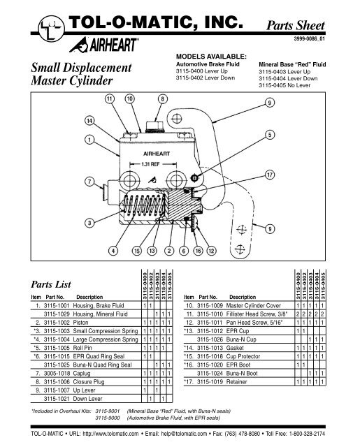
®<strong>TOL</strong>-O-<strong>MATIC</strong>, <strong>INC</strong>.Parts Sheet3999-0086_01®Small DisplacementMaster CylinderMODELS AVAILABLE:Automotive Brake Fluid3115-0400 Lever Up3115-0402 Lever <strong>Down</strong>Mineral Base “Red” Fluid3115-0403 Lever Up3115-0404 Lever <strong>Down</strong>3115-0405 No LeverParts List3115-04003115-04023115-04033115-04043115-0405Item Part No. Description Item Part No. Description1. 3115-1001 Housing, Brake Fluid 1 13115-1029 Housing, Mineral Fluid 1 1 12. 3115-1002 Piston 1 1 1 1 1*3. 3115-1003 Small Compression Spring 1 1 1 1 1*4. 3115-1004 Large Compression Spring 1 1 1 1 1*5. 3115-1005 Roll Pin 1 1 1 1*6. 3115-1015 EPR Quad Ring Seal 1 13115-1025 Buna-N Quad Ring Seal 1 1 17. 3005-1018 Caplug 1 1 1 1 18. 3115-1006 Closure Plug 1 1 1 1 19. 3115-1007 Up Lever 1 13115-1021 <strong>Down</strong> Lever 1 1*Included in Overhaul Kits: 3115-9001 (Mineral Base “Red” Fluid, with Buna-N seals)3115-9000 (Automotive Brake Fluid, with EPR seals)3115-04003115-04023115-04033115-04043115-040510. 3115-1009 Master Cylinder Cover 1 1 1 1 111. 3115-1010 Fillister Head Screw, 3/8" 2 2 2 2 212. 3115-1011 Pan Head Screw, 5/16" 1 1 1 1 1*13. 3115-1012 EPR Cup 1 13115-1026 Buna-N Cup 1 1 1*14. 3115-1013 Gasket 1 1 1 1 1*15. 3115-1018 Cup Protector 1 1 1 1 1*16. 3115-1020 EPR Boot 1 13115-1024 Buna-N Boot 1 1 1*17. 3115-1019 Retainer 1 1 1 1 1<strong>TOL</strong>-O-<strong>MATIC</strong> • URL: http://www.tolom<strong>at</strong>ic.com • Email: help@tolom<strong>at</strong>ic.com • Fax: (763) 478-8080 • <strong>Tol</strong>l Free: 1-800-328-2174
2 – Instructions Small Displacement Master Cylinder Parts Sheet #3999-0086_01INSTALLATION INSTRUCTIONS1. Make certain th<strong>at</strong> <strong>the</strong> master cylinder you <strong>are</strong> using has <strong>the</strong> correct sealsto be comp<strong>at</strong>ible with <strong>the</strong> hydraulic fluid being used in <strong>the</strong> brakingsystem. Master cylinders with EPR seals <strong>are</strong> designed <strong>for</strong> use withAutomotive Brake Fluid which meets <strong>the</strong> standards of SAE J-1703 andDOT 3. Master cylinders with Buna-N seals <strong>are</strong> designed <strong>for</strong> use withmineral base “Red” hydraulic fluid which meets <strong>the</strong> standards ofMil.Spec. MIL-5606.2. Install <strong>the</strong> master cylinder by using <strong>the</strong> two through holes in <strong>the</strong> housing.These holes have clearance <strong>for</strong> 5/16" diameter bolts. Make certain <strong>the</strong>master cylinder is level.Do not exceed 19 foot-pounds of torque when mounting <strong>the</strong> mastercylinder. Excessive torque applied to <strong>the</strong> mounting screws can causedistortion to <strong>the</strong> bore of <strong>the</strong> master cylinder which can result in brakefailure.3. Connect <strong>the</strong> brake linkage.BLEEDINGThe goal of <strong>the</strong> bleeding procedure is to remove any air from <strong>the</strong> brakesystem. Air in <strong>the</strong> system will result in poor brake per<strong>for</strong>mance.CAUTION!Wear adequ<strong>at</strong>e eye protection, gloves and clothing. Brake fluid will cause eyeirrit<strong>at</strong>ion. In case of eye contact, flush with w<strong>at</strong>er <strong>for</strong> 20 minutes and getimmedi<strong>at</strong>e medical <strong>at</strong>tention.NOTE: When filling <strong>the</strong> brake system, use clean, fresh brake fluid froman unopened container. Brake fluid exposed to air can absorb w<strong>at</strong>er.Contamin<strong>at</strong>ed brake fluid can cause brake system failure.Make certain th<strong>at</strong> <strong>the</strong> master cylinder is mounted upright and level above <strong>the</strong>level of <strong>the</strong> brakes.1. Connect <strong>the</strong> hydraulic line to <strong>the</strong> master cylinder outlet port (1/8-27 NPT).DO NOT ATTEMPT TO ENLARGE THE OUTLET PORT IN ANY WAY.Use TEFLON® tape to seal all pipe thread joints.2. Check <strong>the</strong> single small hole (Bypass Port) in <strong>the</strong> floor of <strong>the</strong> mastercylinder reservoir with a very thin wire (0.015" diameter) to see th<strong>at</strong> <strong>the</strong>re<strong>are</strong> no obstructions. The Cup (#13) must not block <strong>the</strong> Bypass Port when<strong>the</strong> piston is retracted. If necessary, adjust <strong>the</strong> Piston Assembly to retract<strong>the</strong> Cup fur<strong>the</strong>r.3. If new brake calipers have been installed, pre-fill calipers by gravityfeeding <strong>the</strong>m with fresh brake fluid into <strong>the</strong> inlet port on <strong>the</strong> brake, with<strong>the</strong> bleeder screw open. When <strong>the</strong> brakes <strong>are</strong> full, close <strong>the</strong> bleederscrews and connect all <strong>the</strong> lines to <strong>the</strong> brakes and master cylinder.4. Start by bleeding <strong>the</strong> brake caliper with <strong>the</strong> longest run of tubing from <strong>the</strong>master cylinder and conclude with <strong>the</strong> brake caliper ne<strong>are</strong>st to <strong>the</strong> mastercylinder.5. A short length of rubber tubing th<strong>at</strong> fits <strong>the</strong> bleed plug nipples tightly shouldbe used to draw off fluid from each caliper during bleeding. The free end of<strong>the</strong> tube must be submerged below some brake fluid <strong>at</strong> <strong>the</strong> bottom of avessel such as a 1 quart glass jar. The tube end must remain submerged<strong>at</strong> all times, or air will be drawn back into <strong>the</strong> system.6. First, make sure <strong>the</strong> bleeder port plugs on <strong>the</strong> brakes <strong>are</strong> closed. Then,with <strong>the</strong> Cover (#10) and Gasket (#14) removed, fill <strong>the</strong> reservoir withfresh high temper<strong>at</strong>ure brake fluid which meets <strong>the</strong> specific<strong>at</strong>ions <strong>for</strong> SAEJ-1703 or DOT 3. (For those braking systems using mineral base “Red”hydraulic fluid make certain <strong>the</strong> fluid meets Mil.Spec. MIL-5606.)NOTE: If DOT 5 brake fluid (silicon) is to be used, <strong>the</strong> entire brake systemMUST be disassembled and washed down with solvent. ALL traces ofDOT 3 brake fluid must be removed be<strong>for</strong>e <strong>the</strong> introduction of DOT 5fluid. Mixing DOT 3 and DOT 5 fluids can result in vapor lock, causinginadequ<strong>at</strong>e or unstable brake per<strong>for</strong>mance.7. When <strong>the</strong> tubes from <strong>the</strong> bleeder plugs <strong>are</strong> submerged in brake fluid,depress <strong>the</strong> brake pedal or lever and hold in position. Then, open onebleeder plug. Repe<strong>at</strong> <strong>the</strong> procedure until air bubbles no longer appear <strong>at</strong><strong>the</strong> end of <strong>the</strong> tubing when <strong>the</strong> pedal or lever is depressed.8. Remember to close <strong>the</strong> bleeder plug port BEFORE releasing <strong>the</strong>brake pedal or lever. Allow <strong>the</strong> pedal or lever to return slowly. Avoidusing excessive pedal pressure during bleeding, as it can cause anunexpected surge of air and fluid from <strong>the</strong> bleeders.9. Repe<strong>at</strong> <strong>the</strong> procedure with each brake. Repe<strong>at</strong> <strong>the</strong> procedure until <strong>the</strong>brake pedal or lever has a firm feel to it.10. Fluid level MUST be maintained in <strong>the</strong> reservoir. Check <strong>the</strong> fluid levelfrequently during bleeding and add more fluid if required.11. After <strong>the</strong> system has been bled, <strong>the</strong> following test should be per<strong>for</strong>med.Observe <strong>the</strong> fluid in <strong>the</strong> reservoir as <strong>the</strong> piston is actu<strong>at</strong>ed <strong>for</strong> <strong>the</strong> firsttime (depress brake pedal or lever). An upward surge in <strong>the</strong> fluid shouldoccur, indic<strong>at</strong>ing pressure in <strong>the</strong> system as <strong>the</strong> piston is released. AHEAVY upward surge in <strong>the</strong> fluid, however, indic<strong>at</strong>es th<strong>at</strong> air is still in <strong>the</strong>system and <strong>the</strong> bleeding procedure must be repe<strong>at</strong>ed.PRESSURE BLEEDINGIf you <strong>are</strong> using a pressure bleeding device, be sure <strong>the</strong> vessel contains asufficient quantity of brake fluid. Prep<strong>are</strong> each brake <strong>for</strong> bleeding as describedabove. Charge <strong>the</strong> device with 20 to 25 PSI of air pressure. Fasten <strong>the</strong> correctmaster cylinder adapter to <strong>the</strong> master cylinder (1/8-27 NPT port). Open <strong>the</strong>feed line to <strong>the</strong> master cylinder. Open <strong>the</strong> bleeder plugs on <strong>the</strong> brake. Close<strong>the</strong> bleeder plugs on <strong>the</strong> brake when no air bubbles escape from <strong>the</strong>submerged ends of <strong>the</strong> rubber tubing in <strong>the</strong> vessels containing <strong>the</strong> brake fluid.NOTE: If <strong>the</strong> master cylinder is loc<strong>at</strong>ed well above <strong>the</strong> brake, allow <strong>the</strong> vehicleto sit <strong>for</strong> a few hours to enable any air trapped in <strong>the</strong> system time to work outof <strong>the</strong> lines and back up to <strong>the</strong> reservoir.DISASSEMBLY1. Disconnect <strong>the</strong> linkage and brake line. Remove <strong>the</strong> master cylinder from<strong>the</strong> vehicle.2. Remove <strong>the</strong> Master Cylinder Cover Screws (#11), <strong>the</strong> Cover (#10) and<strong>the</strong> Gasket (#14). Then drain <strong>the</strong> fluid from <strong>the</strong> reservoir.3. Drive <strong>the</strong> Roll Pin (#5) out with a 1/4" diameter metal rod and remove <strong>the</strong>Lever (#9).4. Hold <strong>the</strong> Piston Retainer (#17) in place and remove <strong>the</strong> Retaining Screw(#12). Release <strong>the</strong> Retainer slowly to avoid loss of parts. Remove all <strong>the</strong>parts.5. Discard all rubber parts and clean all metal parts with solvent. Usecompressed air to dry parts, or allow enough time <strong>for</strong> <strong>the</strong> solvent toevapor<strong>at</strong>e completely, be<strong>for</strong>e reassembling <strong>the</strong>m with new seals.Lubric<strong>at</strong>e parts with brake fluid be<strong>for</strong>e reassembling.ASSEMBLY1. Lubric<strong>at</strong>e <strong>the</strong> housing bore with brake fluid.2. Lubric<strong>at</strong>e <strong>the</strong> Cup (#13) with brake fluid (or mineral base “Red” hydraulicfluid). Place <strong>the</strong> Cup on a fl<strong>at</strong> surface and insert <strong>the</strong> Cup Protector (#15)into <strong>the</strong> Cup, smooth side down.3. Place <strong>the</strong> Small Compression Spring (#3) inside <strong>the</strong> Large CompressionSpring (#4).4. Place one end of <strong>the</strong> Spring Assembly into <strong>the</strong> Cup Protector (#15).5. Pick up <strong>the</strong> Housing (#1) and c<strong>are</strong>fully slide it down over <strong>the</strong> SpringAssembly, Cup Protector (#15) and Cup (#13), until <strong>the</strong> Cup starts into<strong>the</strong> bore.6. Keeping <strong>the</strong> cylinder vertical, pick up <strong>the</strong> Housing and gently push <strong>the</strong>Cup into <strong>the</strong> bore until <strong>the</strong> Spring Assembly starts to compress. Thenturn <strong>the</strong> assembly over.7. Lubric<strong>at</strong>e <strong>the</strong> Quad Ring Seal (#6) (as required) and place it in <strong>the</strong> QuadRing groove on <strong>the</strong> Piston (#2).8. Lubric<strong>at</strong>e <strong>the</strong> Cup and <strong>the</strong> Piston (#2) (as required) and insert <strong>the</strong> Pistoninto <strong>the</strong> bore, fl<strong>at</strong> side first.9. Place <strong>the</strong> Boot (#17) over <strong>the</strong> Piston (#2) and <strong>the</strong> Retainer (#16) over <strong>the</strong>Boot. Then install <strong>the</strong> Pan Head Screw (#12) to hold <strong>the</strong> Retainer inplace.10. Replace <strong>the</strong> Lever (#9) and <strong>the</strong> Roll Pin (#5) so th<strong>at</strong> <strong>the</strong> split in <strong>the</strong> RollPin is facing away from <strong>the</strong> Housing (#1).11. Reinstall <strong>the</strong> master cylinder, connect <strong>the</strong> brake linkage and brake lineand follow <strong>the</strong> Bleeding Instructions.SPECIFICATIONSFLUID:Automotive Brake Fluid - SAE J-1703 or DOT 3Mineral Base “Red” Hydraulic Fluid, Mil.Spec. MIL-5606Displacement: .378 cubic inchesBore Diameter: .875 inchStroke Length: .63 inchWeight: 13 ouncesPort: 1/8-27 NPTMAXIMUM OPERATING PRESSURE: 1000 PSITeflon® is a registered trademark of <strong>the</strong> E.I.DuPont de Nemours Co., www.dupont.comAirheart®, A and heart symbols <strong>are</strong> registered trademarks of <strong>the</strong> Airheart® BrakeDivision of <strong>Tol</strong>-O-M<strong>at</strong>ic, Inc.<strong>TOL</strong>-O-<strong>MATIC</strong>, <strong>INC</strong>.3800 County Road 116, Hamel, MN 55340http://www.<strong>Tol</strong>om<strong>at</strong>ic.com • Email: Help@<strong>Tol</strong>om<strong>at</strong>ic.comPhone: (763) 478-8000 • Fax: (763) 478-8080 • <strong>Tol</strong>l Free: 1-800-328-2174In<strong>for</strong>m<strong>at</strong>ion furnished is believed to be accur<strong>at</strong>eand reliable. However, <strong>Tol</strong>-O-M<strong>at</strong>ic assumes noresponsibility <strong>for</strong> its use or <strong>for</strong> any errors th<strong>at</strong> mayappear in this document. <strong>Tol</strong>-O-M<strong>at</strong>ic reserves <strong>the</strong>right to change <strong>the</strong> design or oper<strong>at</strong>ion of <strong>the</strong>equipment described herein and any associ<strong>at</strong>edmotion products without notice. In<strong>for</strong>m<strong>at</strong>ion inthis document is subject to change without notice.© 2002 <strong>TOL</strong>-O-<strong>MATIC</strong>, <strong>INC</strong>.


