

Parts Sheet - Tolomatic
Parts Sheet - Tolomatic
Parts Sheet - Tolomatic
- No tags were found...

Create successful ePaper yourself
Turn your PDF publications into a flip-book with our unique Google optimized e-Paper software.
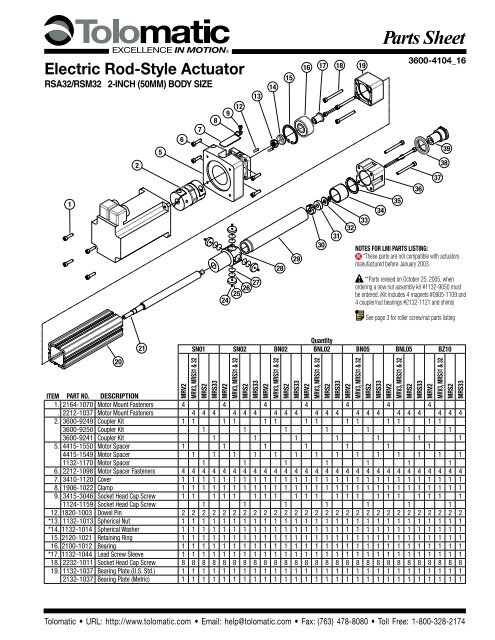
2 – <strong>Parts</strong> Listing RSA32/RSM32<strong>Parts</strong> <strong>Sheet</strong> #3600-4104_16_RSA32psSolid Nut, Ball Nut LMI(Inline motor mount)256789 1213141516 17 18 19393813031323736353433Notes for LMI <strong>Parts</strong> Listing:*These parts are not compatible with actuatorsmanufactured before January 2003.24 25 26 27 2829**<strong>Parts</strong> revised on October 25, 2005, whenordering a new nut assembly kit #1132-9050 mustbe ordered. (Kit includes 4 magnets #0905-1109 and4 coupler/nut bearings #2132-1121 and shims)See page 3 for roller screw/nut parts listing2021QuantitySN01 SN02 BN02 BNL02 BN05 BNL05 BZ10MRV2MRV3, MRS31 & 32MRS2MRS33MRV2MRV3, MRS31 & 32MRS2MRS33MRV2MRV3, MRS31 & 32MRS2MRS33MRV2MRV3, MRS31 & 32MRS2MRS33MRV2MRV3, MRS31 & 32MRS2MRS33MRV2MRV3, MRS31 & 32MRS2MRS33MRV2MRV3, MRS31 & 32MRS2MRS33ITEM PART NO. DESCRIPTION20. 2120-1031 Cylinder Body 1 1 1 1 1 1 1 1 1 1 1 1 1 1 1 12120-1032 Cylinder Body 1 1 1 1 1 1 1 1 1 1 1 1*†21. 2132-1043 Lead Screw .750 OD 2 TPI 1 1 1 12132-1041 Lead Screw .750 OD 2 TPI 1 1 1 1 1 1 1 12132-1040 Lead Screw .750 OD 5 TPI 1 1 1 1 1 1 1 12132-1042 Lead Screw .750 OD 1 TPI 1 1 1 12132-1025 Lead Screw .750 OD 10 TPI 1 1 1 124. 2212-1016 Magnet 4 4 4 4 4 4 4 4 4 4 4 4 4 4 4 4 4 4 4 4 4 4 4 4 4 4 4 425. 2132-1120 Coupler/Nut Bearing 4 4 4 4 4 4 4 4 4 4 4 4 4 4 4 4 4 4 4 4 4 4 4 4 4 4 4 426. 1132-1173 Shim As Required27. 1132-1174 Shim As Required**28. 2132-9021 Nut Assembly 1 1 1 12132-9023 Nut Assembly 1 1 1 1 1 1 1 12132-9024 Nut Assembly 1 1 1 1 1 1 1 12132-9025 Nut Assembly 1 1 1 12132-9026 Nut Assembly 1 1 1 129. 2120-1007 Thrust Tube 1 1 1 1 1 1 1 1 1 1 1 1 1 1 1 1 1 1 1 1 1 1 1 1 1 1 1 130. 1132-1315 Lead Screw Guide 1 1 1 1 1 1 1 1 1 1 1 1 1 1 1 1 1 1 1 1 1 1 1 1 1 1 1 131. 2120-1029 Bumper 1 1 1 1 1 1 1 1 1 1 1 1 1 1 1 1 1 1 1 1 1 1 1 1 1 1 1 132. 2120-1018 Washer 1 1 1 1 1 1 1 1 1 1 1 1 1 1 1 1 1 1 1 1 1 1 1 1 1 1 1 133. 0910-1198 External Retaining Ring 1 1 1 1 1 1 1 1 1 1 1 1 1 1 1 1 1 1 1 1 1 1 1 1 1 1 1 134. 2120-1023 Bearing Sleeve 1 1 1 1 1 1 1 1 1 1 1 1 1 1 1 1 1 1 1 1 1 1 1 1 1 1 1 135. 2120-1020 O-Ring 1 1 1 1 1 1 1 1 1 1 1 1 1 1 1 1 1 1 1 1 1 1 1 1 1 1 1 136. 1132-1002 Machined Head (U.S. Std.) 1 1 1 1 1 1 1 1 1 1 1 1 1 1 1 1 1 1 1 1 1 1 1 1 1 1 1 12120-1002 Machined Head (Metric) 1 1 1 1 1 1 1 1 1 1 1 1 1 1 1 1 1 1 1 1 1 1 1 1 1 1 1 138. 2120-1030 Wiper Seal 1 1 1 1 1 1 1 1 1 1 1 1 1 1 1 1 1 1 1 1 1 1 1 1 1 1 1 139. 1132-1006 Rod End (U.S. Std.) 1 1 1 1 1 1 1 1 1 1 1 1 1 1 1 1 1 1 1 1 1 1 1 1 1 1 1 12120-1006 Rod End (Metric) 1 1 1 1 1 1 1 1 1 1 1 1 1 1 1 1 1 1 1 1 1 1 1 1 1 1 1 1† Must indicate stroke length when ordering. Configurated code is the preferred ordering method: RLS RS_32 ____ SK_____ MR____Example: RLS RSA32 SN01 SK21.25 MRV231Replacement Lead ScrewModel & Size Nut Style & Size Stroke Length Motor Code<strong>Tolomatic</strong> • URL: http://www.tolomatic.com • Email: help@tolomatic.com • Fax: (763) 478-8080 • Toll Free: 1-800-328-2174
<strong>Parts</strong> <strong>Sheet</strong> #3600-4104_16_RSA32ps RSA32/RSM32 <strong>Parts</strong> Listing – 3Roller Nut LMI(Inline motor mount)161718 192345678910111215131445343536373840414443394231129302524262728<strong>Parts</strong> ListingMRV2QuantityRN05MRV3/MRS31 & 32MRS33ITEM PART NO. DESCRIPTION1. 2312-1057 Socket Head Cap Screw 42212-1098 Socket Head Cap Screw 4 42. 3600-6190 Coupler Half 1 13600-6191 Coupler Half 13. 3600-6326 Spider 1 1 14. 1132-1154 Coupler Half 1 1 15. 3420-1350 Motor Spacer 18340-1121 Motor Spacer 1 16. 4415-1063 Socket Head Cap Screw 4 4 47. 3410-1120 Cover 1 1 18. 1906-1022 Clamp 1 1 19. 1124-1159 Socket Head Cap Screw 1 1 110. 0601-2070 Socket Head Cap Screw 4 4 411. 1132-1319 Adaptor Plate 1 1 112. 1820-1003 Dowel Pin 4 4 413. 2733-1016 Lock Nut 1 1 114. 1132-1310 Spacer 1 1 115. 1132-1303 Lock Ring 1 1 116. 1132-1304 Bearing 2 2 2202221MRV2QuantityRN05MRV3/MRS31 & 32MRS33ITEM PART NO. DESCRIPTION17. 1132-1309 Leadscrew Sleeve 1 1 118. 1132-1324 Socket Head Cap Screw 4 4 419. 1132-1302 Bearing Plate 1 1 12132-1302 Bearing Plate (Metric) 1 1 120. 1132-1300 Cylinder Body 1 1 121. 1132-1322 Leadscrew/roller Nut 1 1 122. 2744-1008 Nut Housing Cover 1 1 124. 2212-1016 Magnet 4 4 425. 2132-1120 Nut Housing Bearing 4 4 426. 1132-1173 Shim AR AR AR27. 1132-1174 Shim AR AR AR28. 1132-1306 Nut Housing 1 1 129. 1132-1301 Thrust Tube 1 1 130. 1132-1315 Bushing 1 1 131. 1132-1314 Shoulder Bolt 1 1 134. 2120-1023 Bearing 1 1 135. 2120-1020 O-ring 1 1 136. 1132-1002 Head 1 1 12120-1002 Head (Metric) 1 1 137. 2232-1011 Socket Head Cap Screw 4 4 438. 2120-1030 Wiper 1 1 139. 1132-1313 Rod End 1 1 12132-1313 Rod End (Metric) 1 1 140. 2403-1055 Retaining Ring 1 1 141. 1132-1317 Strike Plate 1 1 142. 2733-1009 Bumper 1 1 143. 0520-1284 Ball 1 1 144. 0100-1601 Zerk Fitting 1 1 145. 1132-1320 Bearing Seal 1 1 1<strong>Tolomatic</strong> • URL: http://www.tolomatic.com • Email: help@tolomatic.com • Fax: (763) 478-8080 • Toll Free: 1-800-328-2174
4 – <strong>Parts</strong> Listing RSA32/RSM32 <strong>Parts</strong> <strong>Sheet</strong> #3600-4104_16_RSA32psSolid Nut, Ball Nut RP(Reverse Parallel motor mount)876523416171819Notes for RP <strong>Parts</strong> Listing:*These parts are not compatible with actuatorsmanufactured before January 2003.See page 6 for roller screw/nut parts listing11514131:1 RATIOSN01 SN02 BN02 BN05 BZ109101112MRV2MRV3/MRS31 & 32MRS2MRS33MRV2MRV3/MRS31 & 32MRS2MRS33MRV2MRV3/MRS31 & 32MRS2MRS33MRV2MRV3/MRS31 & 32MRS2MRS33MRV2MRV3/MRS31 & 32MRS2MRS33ITEM PART NO. DESCRIPTION1 0601-1143 Socket Head Cap Screw 4 4 4 4 4 4 4 4 4 4 4 4 4 4 4 4 4 4 4 41132-1351 RP Cover 1 1 1 1 1 1 1 1 1 121132-1353 RP Cover 1 1 1 1 1 1 1 1 1 12132-1002 Motor Pulley 1 1 1 1 1 1 1 1 1 13 1132-1010 Motor Pulley 1 1 1 1 11132-9029 Motor Pulley 1 1 1 1 141132-1023 Belt 1 1 1 1 12120-1026 Belt 1 1 1 1 1 1 1 1 1 12132-1007 Belt 1 1 1 1 10520-1067 Collar Clamp 1 1 1 1 1 1 1 1 1 15 2307-1005 Collar Clamp 1 1 1 1 12324-1005 Collar Clamp 1 1 1 1 16 8316-1501 Square Nuts 4 4 4 4 4 4 4 4 4 4 4 4 4 4 4 4 4 4 4 4781132-1358 RP Plate 1 1 1 1 1 1 1 1 1 11132-1363 RP Plate 1 1 1 1 1 1 1 1 1 13415-1721 Motor Mount Fasteners 4 4 4 4 42212-1099 Motor Mount Fasteners 4 4 4 4 4 4 4 4 4 44415-1063 Motor Mount Fasteners 4 4 4 4 49 2212-1103 Socket Head Cap Screw 2 2 2 2 2 2 2 2 2 2 2 2 2 2 2 2 2 2 2 2*10 1132-1013 Spherical Lock Nut 1 1 1 1 1 1 1 1 1 1 1 1 1 1 1 1 1 1 1 1*11 1132-1014 Spherical Washer 1 1 1 1 1 1 1 1 1 1 1 1 1 1 1 1 1 1 1 112 2132-1005 Actuator Pulley 1 1 1 1 1 1 1 1 1 1 1 1 1 1 1 1 1 1 1 113 2120-1024 Key 1 1 1 1 1 1 1 1 1 1 1 1 1 1 1 1 1 1 1 114 2120-1021 Retaining Ring 1 1 1 1 1 1 1 1 1 1 1 1 1 1 1 1 1 1 1 115 0515-1332 Socket Head Cap Screw 2 2 2 2 2 2 2 2 2 2 2 2 2 2 2 2 2 2 2 216 2100-1012 Bearing 1 1 1 1 1 1 1 1 1 1 1 1 1 1 1 1 1 1 1 1*17 1132-1044 Leadscrew Sleeve 1 1 1 1 1 1 1 1 1 1 1 1 1 1 1 1 1 1 1 118*191132-1354 Bearing Plate 1 1 1 1 1 1 1 1 1 1 1 1 1 1 1 1 1 1 1 12132-1354 Bearing Plate (Metric) 1 1 1 1 1 1 1 1 1 1 1 1 1 1 1 1 1 1 1 12132-1042 Leadscrew 1 1 1 12132-1043 Leadscrew 1 1 1 12132-1041 Leadscrew 1 1 1 12132-1040 Leadscrew 1 1 1 12132-1025 Leadscrew 1 1 1 1<strong>Tolomatic</strong> • URL: http://www.tolomatic.com • Email: help@tolomatic.com • Fax: (763) 478-8080 • Toll Free: 1-800-328-2174
<strong>Parts</strong> <strong>Sheet</strong> #3600-4104_16_RSA32ps RSA32/RSM32 <strong>Parts</strong> Listing – 5Solid Nut, Ball Nut RP(Reverse Parallel motor mount)876523416171819Notes for RP <strong>Parts</strong> Listing:*These parts are not compatible with actuatorsmanufactured before January 2003.See page 6 for roller screw/nut parts listing11514132:1 RATIOSN01 SN02 BN02 BN05 BZ109101112MRV2MRV3/MRS31 & 32MRS2MRS33MRV2MRV3/MRS31 & 32MRS2MRS33MRV2MRV3/MRS31 & 32MRS2MRS33MRV2MRV3/MRS31 & 32MRS2MRS33MRV2MRV3/MRS31 & 32MRS2MRS33ITEM PART NO. DESCRIPTION1 0601-1143 Socket Head Cap Screw 4 4 4 4 4 4 4 4 4 4 4 4 4 4 4 4 4 4 4 41132-1351 RP Cover 1 1 1 1 1 1 1 1 1 121132-1353 RP Cover 1 1 1 1 1 1 1 1 1 11132-9049 Motor Pulley 1 1 1 1 1 1 1 1 1 13 1132-1010 Motor Pulley 1 1 1 1 11132-9029 Motor Pulley 1 1 1 1 142120-1026 Belt 1 1 1 1 11132-1215 Belt 1 1 1 1 1 1 1 1 1 12132-1018 Belt 1 1 1 1 10520-1067 Collar Clamp 1 1 1 1 1 1 1 1 1 15 2307-1005 Collar Clamp 1 1 1 1 12324-1005 Collar Clamp 1 1 1 1 16 8316-1501 Square Nuts 4 4 4 4 4 4 4 4 4 4 4 4 4 4 4 4 4 4 4 4781132-1358 RP Plate 1 1 1 1 1 1 1 1 1 11132-1363 RP Plate 1 1 1 1 1 1 1 1 1 13415-1721 Socket Head Cap Screw 4 4 4 4 42212-1098 Socket Head Cap Screw 4 4 4 4 4 4 4 4 4 44415-1063 Socket Head Cap Screw 4 4 4 4 49 2212-1103 Socket Head Cap Screw 2 2 2 2 2 2 2 2 2 2 2 2 2 2 2 2 2 2 2 2*10 1132-1013 Spherical Lock Nut 1 1 1 1 1 1 1 1 1 1 1 1 1 1 1 1 1 1 1 1*11 1132-1014 Spherical Washer 1 1 1 1 1 1 1 1 1 1 1 1 1 1 1 1 1 1 1 112 2132-1006 Actuator Pulley 1 1 1 1 1 1 1 1 1 1 1 1 1 1 1 1 1 1 1 113 2120-1024 Key 1 1 1 1 1 1 1 1 1 1 1 1 1 1 1 1 1 1 1 114 2120-1021 Retaining Ring 1 1 1 1 1 1 1 1 1 1 1 1 1 1 1 1 1 1 1 115 0515-1332 Socket Head Cap Screw 2 2 2 2 2 2 2 2 2 2 2 2 2 2 2 2 2 2 2 216 2100-1012 Bearing 1 1 1 1 1 1 1 1 1 1 1 1 1 1 1 1 1 1 1 1*17 1132-1044 Leadscrew Sleeve 1 1 1 1 1 1 1 1 1 1 1 1 1 1 1 1 1 1 1 118*191132-1354 Bearing Plate 1 1 1 1 1 1 1 1 1 1 1 1 1 1 1 1 1 1 1 12132-1354 Bearing Plate (Metric) 1 1 1 1 1 1 1 1 1 1 1 1 1 1 1 1 1 1 1 12132-1042 Leadscrew 1 1 1 12132-1043 Leadscrew 1 1 1 12132-1041 Leadscrew 1 1 1 12132-1040 Leadscrew 1 1 1 12132-1025 Leadscrew 1 1 1 1<strong>Tolomatic</strong> • URL: http://www.tolomatic.com • Email: help@tolomatic.com • Fax: (763) 478-8080 • Toll Free: 1-800-328-2174
6 – <strong>Parts</strong> Listing RSA32/RSM32 <strong>Parts</strong> <strong>Sheet</strong> #3600-4104_16_RSA32psRoller Nut RP(Reverse Parallel motor mount)871961851734221612201413151:1 RATIO 2:1 RATIORN05 RN05<strong>Parts</strong> Listing91012MRV21:1 RATIO 2:1 RATIORN05 RN05MRV3/MRS31 & 32MRS33MRV2MRV3/MRS31 & 32MRS33ITEM PART NO. DESCRIPTION1. 0601-1143 Socket Head Cap Screw 4 4 4 4 4 42. 1132-1351 RP Cover 1 11132-1353 RP Cover 1 1 1 13. 1132-9049 Motor Pulley 1 1 1 11132-9029 Motor Pulley 1 14. 1132-1023 Belt 12120-1026 Belt 1 11132-1215 Belt 1 15. 0520-1067 Collar Clamp 1 1 1 12324-1005 Collar Clamp 1 16. 8316-1501 Square Nuts 4 4 4 4 4 4MRV2MRV3/MRS31 & 32MRS33MRV2ITEM PART NO. DESCRIPTION7. 1132-1358 RP Plate 1 1MRV3/MRS31 & 32MRS331132-1363 RP Plate 1 1 1 18. 3415-1921 Motor Mount Fasteners 4 42212-1098 Motor Mount Fasteners 4 4 4 49. 1132-1308 Socket Head Cap Screw 2 2 2 2 2 210. 2733-1016 Lock Nut 1 1 1 1 1 112. 2132-1005 Actuator Pulley 1 1 12132-1006 Actuator Pulley 1 1 113. 2120-1024 Key 1 1 1 1 1 114. 1132-1303 Lock Ring 1 1 1 1 1 115. 2750-1058 Socket Head Cap Screw 2 2 2 2 2 216. 1132-1304 Bearing 2 2 2 2 2 217. 1132-1309 Leadscrew Sleeve 1 1 1 1 1 118. 1132-1302 Bearing Plate 1 1 1 1 1 12132-1302 Bearing Plate (Metirc) 1 1 1 1 1 119. 1132-1321 Leadscrew 1 1 1 1 1 122. 1132-1320 Bearing Seal 1 1 1 1 1 1<strong>Tolomatic</strong> • URL: http://www.tolomatic.com • Email: help@tolomatic.com • Fax: (763) 478-8080 • Toll Free: 1-800-328-2174
<strong>Parts</strong> <strong>Sheet</strong> #3600-4104_16_RSA32ps RSA32/RSM32 Instructions – 7DISASSEMBLY INSTRUCTIONSBegin with a clean work area. Be sure all replacement parts arepresent and have no visual damage or defects. The following toolsare recommended for proper disassembly and assembly.• Allen wrench set• Socket wrench & socket set• Retaining ring pliers1. Remove motor and motor mounting hardware:LMI, Solid Nut/Ball Nut: (Note: Reference parts list from page1, 2.) Remove components in the following order:1) Remove Cover (7) by loosening Screw (9).2) Loosen the coupler screw closest to the actuator.3) Remove Motor Mount Fasteners (1) and Motor/CouplerAssembly (2)4) Remove Motor Spacer Fasteners (6) and Motor Spacer (5)LMI, Roller Nut: (Note: Reference parts list from page 3.)Remove components in the following order:1) Remove Cover (7) by loosening Screw (9).2) Loosen the coupler screw closest to the actuator.3) Remove Motor Mount Fasteners (1) and Motor/CouplerAssembly (2)4) Remove Motor Spacer Fasteners (6) and Motor Spacer (5)5) Remove the Adapter Plate (11) by removing the SocketHead Cap Screws (10).RP, Solid Nut/Ball Nut: (Note: Reference parts list from page4, 5 whenever instructions refer to RP with Solid Nut/Ball Nut.)Disassemble the RP [Reverse Parallel] assembly in the followingorder:1) Loosen the Motor Mount Fasteners (8) to remove belttension,2) Remove RP Cover (2) by removing the six Socket Head CapScrews (1,9),3) Remove Belt (4),4) Remove the motor by removing the Motor MountFasteners (8) and the Square Nuts (6).5) Remove the RP Plate (7) by removing two Socket HeadCap Screws (15). Note: the Retaining Ring (14) is part of the RPPlate. A portion of the Bearing (16) will be protruding from theBearing Plate (18). The Bearing Plate (18) is no longer securedto the actuator body.RP, Roller Nut: (Note: Reference parts list from page 6whenever instructions refer to RP with Roller Nut.) Disassemblethe RP [Reverse Parallel] assembly in the following order:1) Loosen the Motor Mount Fasteners (8) to remove belttension,2) Remove RP Cover (2) by removing the six Socket Head CapScrews (1,9),3) Remove Belt (4),4) Remove the motor by removing the Motor MountFasteners (8) and the Square Nuts (6).5) Remove the RP Plate (7) by removing two Socket Head CapScrews (15).2. Separate Cylinder Body (20) from Bearing Plate (19):LMI, All Nuts: Remove the 4 Socket Head Cap Screws (18) thathold the Bearing Plate (19) to the Cylinder Body (20).RP, Solid Nut/Ball Nut: There are no screws to remove theBearing Plate (19) since the screws were removed during RPmotor and motor mount hardware removal.LMI, RP, All Nuts: Slide the Cylinder Body (20) away fromBearing Plate (19) and off of the Nut Coupler (28) /ThrustTube (29) assembly.Caution: Mark the location of the 4 Nut Coupler Bearings (25)and Shims (26,27) relative to the Cylinder Body (20). These NutCoupler Bearings (25) and Shims (26,27) are fitted at the factoryand their orientation is critical when reassembling the actuator.If needed, the non-motor end Head (36) can also be removedfrom the Cylinder Body (20) by removing the 4 Socket Head CapScrews (37).3. Remove the Thrust Tube (29) from the Nut Coupler/Housing (28):The Thrust Tube (29) is threaded to the Nut Coupler/Housing (28)and held in place with Loctite. To remove the Thrust Tube (29),slide the O-Ring (35) off the end of the Thrust Tube (29),then apply heat at the interface between the Nut Coupler/Housing (28) and Thrust Tube (29), until Loctite becomespliable enough to release the threads. Place a wrench on theflats of the machined Rod End (39) and turn counterclockwiseto unscrew the Thrust Tube (29) from the Nut Coupler/Housing (28). To remove the Rod End (39) from the ThrustTube (29) place Thrust Tube (29) into vise, apply heat to thethreaded joint to make Loctite pliable then use wrench on flatsof Rod End (39) to remove.4. Remove the Leadscrew (21) from the Nut Assembly (28):Solid Nut/Ball Nut: Remove the Bearing Sleeve (34) from theLeadscrew (21).Ball Nut: *Caution is required if removal of the NutAssembly (28) or Leadscrew (21) is required. Contact the factoryfor available parts and procedures.Solid Nut: The Leadscrew (21) can be threaded out of theNut Assembly (28) at this point. If leadscrew worn, a new NutAssembly (28) must be ordered.Roller Nut: *Caution: Never remove the roller nut from theleadscrew. To remove the Leadscrew/Roller Nut (21) from theNut Housing (28) remove the Nut Housing Cover (22) usinga spanner tool. The Nut Housing Cover (22) is installed withLoctite so it may be necessary to apply heat to the joint beforeremoval.5. Remove the Leadscrew/Roller Nut (21) from the BearingPlate (19): Secure the body of the Leadscrew/Roller Nut (21) ina machinist vice or equivalent smooth jaw vice then remove theLock Nut (13). NOTE: Lock Nut (13) for the Leadscrew/RollerNut (21) requires special tooling for removal. For a Leadscrew/Roller Nut (21), remove the Spacer (14) and Bearing Seal (45).Support the inner race of Bearing (16) and press the Leadscrew/Roller Nut (21) out of the Leadscrew Sleeve (17). There is amating taper interface between the Leadscrew Sleeve (17) andthe Leadscrew/Roller Nut (21).<strong>Tolomatic</strong> • URL: http://www.tolomatic.com • Email: help@tolomatic.com • Fax: (763) 478-8080 • Toll Free: 1-800-328-2174
8 – <strong>Parts</strong> Listing RSA32/RSM32 <strong>Parts</strong> <strong>Sheet</strong> #3600-4104_16_RSA32ps6. Remove Bearing (16) from the Bearing Plate (19):Solid Nut/Ball Nut: Remove the Retaining Ring (15) and pressthe Bearing (16) out of the Bearing Plate (19) as it is secured inplace with retaining compound.Roller Nut: Remove the Lock Ring (15) from the BearingPlate (19). Loctite is used on the Lock Ring (15) so heat may beneeded to make the loctite pliable. Press the two Bearings (16)out of the Bearing Plate (19) as they are secured in place withretaining compound.ASSEMBLY INSTRUCTIONS1. Sub-assemble Wiper (38) and Bearing (34) into Head (36):Install Wiper (38) with the lip on inside diameter facing outwardinto the groove in the Head (36). Press the Bearing Sleeve (34)from opposite end of Head (36) until it is flush to surface ofHead (36).2. Sub-assemble the Bearing (16) into Bearing Plate (19):Solid Nut/Ball Nut: Press Leadscrew Sleeve (17) into mainBearing (16). Apply Loctite 641 retaining compound to OD ofthe Bearing (16) and ID of the Bearing Plate (19) and installBearing (16) into the Bearing Plate (19). LMI only, install theSnap Ring (15).Roller Nut: Stack the 2 Bearings (16) onto each other so thenon-flanged inner races are touching. Press the LeadscrewSleeve (17) into both Bearings (16). Apply Loctite 641 retainingcompound to OD of both Bearings (16) and the ID bore of theBearing Plate (19). Install the bearing assembly into the BearingPlate (19) then install the Lock Ring (15). Use the flats on theLeadscrew Sleeve (17) while tightening the Lock Ring (15).3. Install Bearing Plate (19) assembly onto leadscrew/nut:LMI, Solid Nut/Ball Nut: Install Leadscrew (21) into theLeadscrew Sleeve (17) in Bearing Plate (19) assembly. ApplyLoctite 242 to the threads of the Leadscrew (21) then locateWasher (14) and Locknut (13) over Leadscrew (21). Torque theLock Nut (13) to 200 in-lbs, hold Leadscrew (21) in machinistvice as necessary.RP, Solid Nut/Ball Nut: (Reference parts list on page 6.) InstallLeadscrew (21) into the Leadscrew Sleeve (17) and applyLoctite 242 to the threads of the Leadscrew (21). Place Key (13)onto Leadscrew (21) and install the Pulley (12), Washer (11), andLock Nut (10) over Leadscrew (21). Torque Lock Nut (10) to 200in-lbs. Hold Leadscrew (21) in machinist vice as necessary.LMI, Rollerscrew: (Reference parts list on page 3.) Fromthe motor end of the Leadscrew/Roller Nut (21) slide the NutHousing Cover (22) onto the Leadscrew/Roller Nut (21) so it fitsover roller nut. Install the Leadscrew/Roller Nut (21) into theLeadscrew Sleeve (17) in Bearing Plate (19) assembly. Installthe Bearing Seal (45) and Spacer (14) onto Leadscrew/RollerNut (21) and secure using Lock Nut (13). Note: Lock Nut (13)requires special tool to install.4. Install nut with Nut Coupler/Housing (28) onto leadscrew/nut:Solid Nut/Ball Nut: Thread the Nut Assembly (28) onto theLeadscrew (21). Threaded end of the Nut Assembly (28) is awayfrom motor end of the Leadscrew (21).Roller Nut: NOTE: The roller nut must never be removedfrom the Leadscrew/Roller Nut (21). Align the slot in the NutHousing (28) with key on the roller nut on the Leadscrew/RollerNut (21) and slide Nut Housing (28) onto the roller nut from thenon-motor end of the Leadscrew/Roller Nut (21). Apply Loctite271 onto the ID threads of the Nut Coupler Cover (22). Fromthe motor end of the Leadscrew/Roller Nut (21), thread on NutHousing Cover (22) onto the Nut Housing (28). Make sure not toget any loctite on the leadscrew or roller nut.5. Assemble Bushing (30) onto non-motor end of leadscrew/nut:Solid Nut/Ball Nut: Slide the leadscrew Bushing (30),Bumper (31), Washer (32) onto non-motor end of theLeadscrew (21) and secure using Retaining Ring (33).Roller Nut: Slide the rollerscrew Bushing (30) onto theShoulder Bolt (31) and install Shoulder Bolt (31) onto end of theLeadscrew/Roller Nut (21).6. Grease leadscrew/nut and ID of the Thrust Tube (29) with thefollowing grease:Ball Nut/Bronze Nut Units: Grease w/ Mobil HP greaseSolid Nut Units: Grease w/ Christolube MCG #405Roller Nut Units: <strong>Tolomatic</strong> Grease #2744-90997. Install Thrust Tube (29) onto Nut Coupler/Housing (28):Apply Loctite 270 to OD threads on Thrust Tube (29) andassemble Thrust Tube (29) to Nut Coupler/Housing (28).8. Grease ID of Cylinder Body (20) w/ a coating of ChristolubeMCG #405 grease, and install leadscrew/nut assembly intothe Cylinder Body (20). *Make sure to orient Nut HousingBearing (25) with respect to tube the same as were removed.9. Attach Head (36) and Bearing Plate (19) assembly to theCylinder Body (20) and align prior to tightening:LMI, Solid Nut/Ball Nut:A. Align motor end Bearing Plate (19) assembly to CylinderBody (20) with Thrust Tube (29) retracted, and then tightenSocket Head Cap Screws (18).B. Align non-motor end Head (36) to Cylinder Body (20) withThrust Tube (29) extended, and then tighten Socket HeadCap Screws (37).RP, Solid Nut/Ball Nut:A. (See page 4, 5 parts list for this step.) Install the RPPlate (7) through Bearing Plate (18) to Cylinder Body (20)with Thrust Tube (29) retracted, and then tightening twoSocket Head Cap Screws (15) into the top two holes in theRP Plate (7). Install Retaining Ring (14).B. (See page 1, 2 parts list for this step.) Align non-motorend Head (36) to Cylinder Body (20) with Thrust Tube (29)extended, and then tighten Socket Head Cap Screws (37).RP, Roller Nut:A. (See page 6 parts list for this step.) Install the RP Plate (7)through Bearing Plate (18) to Cylinder Body (20) withThrust Tube (29) retracted, and then tightening two SocketHead Cap Screws (15) into the top two holes in the RPPlate (7).<strong>Tolomatic</strong> • URL: http://www.tolomatic.com • Email: help@tolomatic.com • Fax: (763) 478-8080 • Toll Free: 1-800-328-2174
<strong>Parts</strong> <strong>Sheet</strong> #3600-4104_16_RSA32ps RSA32/RSM32 <strong>Parts</strong> Listing – 9B. (See page 3 parts list for this step.) Align non-motor endHead (36) to Cylinder Body (20) with Thrust Tube (29)extended, and then tighten Socket Head Cap Screws (37).10. Install Rod End (39) into Thrust Tube (29):Solid Nut/Ball Nut: Apply Loctite 271 to threads of the RodEnd (39), install and tighten to the Thrust Tube (29).Roller Nut: Insert the Bumper (42) then the Strike Plate (41)into the Rod End (39) and secure using Retaining Ring (40).Apply Loctite 271 to threads of the Rod End (39), install andtighten to the Thrust Tube (29). Install Zerk (44) if needed.11. Roller Nut only: Fill the Thrust Tube (29) with <strong>Tolomatic</strong>Grease #2744-9099 via the Zerk (44) installed on the RodEnd (39).LMI MOTOR ASSEMBLY INSTRUCTIONSSolid Nut/Ball Nut:1. Attach Coupler Half (2) onto leadscrew/nut then insert Spider (2)into Coupler Half (2). Insert the other Coupler Half (2) into theSpider (2).2. Install Motor Spacer (5) to Bearing Plate (19) using MotorSpacer Fasteners (6).3. Install motor to Motor Spacer (5) using Motor MountFasteners (1). Motor shaft should fit into the ID bore of theCoupler Half (2). Tighten the Coupler Half (2) onto the motorshaft through access hole in Motor Spacer (5).4. Place Cover (7) onto Motor Spacer (5) to cover the accesshole. Secure Cover (7) using Clamp (8) and Socket Head CapScrew (9).Roller Nut:1. Install Adapter Plate (11) to the Bearing Plate (19) by thealigning Dowel Pins (12) and Socket Head Cap Screws (10).2. Attach Coupler Half (2) onto leadscrew/nut then insert Spider (2)into Coupler Half (2). Insert the other Coupler Half (2) into theSpider (2).3. Install Motor Spacer (5) to Adapter Plate (11) using MotorSpacer Fasteners (6).4. Install motor to Motor Spacer (5) using Motor MountFasteners (1). Motor shaft should fit into the ID bore of theCoupler Half (2). Tighten the Coupler Half (2) onto the motorshaft through access hole in Motor Spacer (5).5. Place Cover (7) onto Motor Spacer (5) to cover the accesshole. Secure Cover (7) using Clamp (8) and Socket Head CapScrew (9).REVERSE PARALLEL MOTOR ASSEMBLY INSTRUCTIONS1. Align motor with slots RP Plate (7). Install four Motor MountFasteners (8) through motor and RP Plate (7) then into the fourSquare Nuts (6). The Square Nuts (6) must seat into the pocketsof the RP Plate (7). Tighten enough so motor is not drooping butable to move vertically.2. Align the Collar Clamp (5) with the Motor Pulley (3) and installthe Motor Pulley (3) onto the motor shaft by tightening theCollar Clamp (5) fastener. Align motor pulley with the actuatorpulley (12).3. Slide belt (4) over motor pulley (3) and actuator pulley (12).4. Attach RP cover (2) to RP plate (7):Install RP cover (2) using two long fasteners (9) through theRP cover, RP plate and bearing plate (18) and into cylinderbody (20). Install the remaining four fasteners (1) into the RPplate.5. Tension the belt (4) by pulling the motor away from theleadscrew/rollerscrew with the appropriate force in the chartbelow. Tighten the motor fasteners (8) while this force is appliedto the motor.Motor FrameMRB23, MRS17/23MRV23, MRS34MRV34, MRB34Tension Force10 lbs20 lbs30 lbsChristo-Lube ® is a registered trademark of Lubrication Technology,Inc., www.lubricationtechnology.comLoctite ® is a registered trademark of the Loctite Corporation, www.loctite.comMobil grease ® HP is a registered trademark of Mobil Oil Corporation,www.mobil.com<strong>Tolomatic</strong> • URL: http://www.tolomatic.com • Email: help@tolomatic.com • Fax: (763) 478-8080 • Toll Free: 1-800-328-2174
10 – Roller Screw Lubrication RSA32/RSM32<strong>Parts</strong> <strong>Sheet</strong> #3600-4104_16_RSA32psRoller Screw LubricationNOTE! Before starting any maintenance activities, makesure that the supply power is shut OFF.! CAUTION: DO NOT FILL WITH GREASE!RSA/RSM actuators have been lubricated at the factoryand are ready for installation. For many applications theactuator is greased for life.• For light to moderate use, no additionallubrication is required.Overfilling will cause a reduction in performance, excessiveheat build up and potential premature failure.All curves represent properly lubricated and maintainedactuators.Roller Screw• For optimal performance and rated life, periodicre-lubrication is required. Select the BasicLubrication Interval (t BL ) based on the cycles RMSVelocity (V RMS ). Use either the formula or the graphbelow.t BL = 4500 x (V RMS ) -1.57 (hours)Lubrication Interval (hrs)100,00010,0001,0001000 1 2 3 4 5 6 7 8Cycle RMS Velocity (in/sec)1Roller Screw Lubrication Interval Graph• Determine the Thrust Correction Factor (K T )based on the ratio of the Actuator Peak ThrustRating (T PEAK ) to the Maximum Cycle Thrust (T MAX ).Important NOTE:K T can not be greater than 1.TK T = K Co (PEAK) - 0.15T MAX24RN05 32RN05K Co 0.24 0.26• The Lubrication Interval (t L ) for a givencycle is then calculated as:t L = t BL x K T (hours)• Re-lubricate with <strong>Tolomatic</strong> Grease #2744-1021Quantity: RSA24/RSM24 Approximately 0.1 oz. (3 g);RSA32/RSM32: Approximately 0.2 oz. (6 g) throughgrease zerk.WARNING!There is a possibility that base oil may leak from theGrease Zerk (#2). In contamination sensitive applicationsreplace Grease Zerk (#2) with a leak-proof Grease FittingPlug (#4), or add a leak-resistant Grease Zerk Cap (#5) tocover Grease Zerk (#2).523 4Item Part No. DescriptionWhere:t BL = Basic Lubrication Interval (hours)V RMS = RMS Velocity (in/sec)K T = Thrust Correction FactorK Co = Screw Static Load FactorT PEAK = Actuator Peak Thrust RatingT MAX =Maximum Cycle Thrustt L = Lubrication Interval (hours)2. 0100-1601 Zerk, Fitting, 1/4-283. 2309-1055 Set Screw, 1/4-28 (Flush zerk replacement)4. 2744-1214 Grease Fitting Plug, 1/4-28 (leak-proof)5. 2744-1213 Grease Zerk Cap (leak-resistant)<strong>Tolomatic</strong> • URL: http://www.tolomatic.com • Email: help@tolomatic.com • Fax: (763) 478-8080 • Toll Free: 1-800-328-2174
<strong>Parts</strong> <strong>Sheet</strong> #3600-4104_16_RSA32ps RSA32/RSM32 <strong>Parts</strong> Listing – 11242520212223262710123<strong>Parts</strong> Listing456QuantityRSA32RSM32ITEM PART NO. DESCRIPTIONCLEVIS MOUNT (PCD)1132-9025 Clevis Mount Kit 12132-9045 Clevis Mount Kit 11. 1124-1056 Clevis Pin 12132-1056 Clevis Pin 12. 3415-1460 Socket Head Cap Screw 42212-1101 Socket Head Cap Screw 43. 1132-1055 Clevis 12132-1055 Clevis 110. 1132-1329 RP Cover (23 Frame) 11132-1365 RP Cover (23 Frame) 11132-1334 RP Cover (34 Frame) 11132-1368 RP Cover (34 Frame) 1BACK FLANGE [REAR FLANGE] (BFG)1132-9022 Back Flange Kit 12132-9042 Back Flange Kit 14. 3415-1206 Socket Head Cap Screw 40604-1027 Socket Head Cap Screw 45. 1132-1052 Flange Plate 12132-1052 Flange Plate 110. 1132-1329 RP Cover (23 Frame) 11132-1365 RP Cover (23 Frame) 11132-1334 RP Cover (34 Frame) 11132-1368 RP Cover (34 Frame) 1879111213141516171819NOTE: See page 13 forswitch kit informationQuantityRSA32RSM32ITEM PART NO. DESCRIPTIONEYE MOUNT (PCS)1132-9024 Eye Mount Kit 12132-9044 Eye Mount Kit 16. 3415-1460 Socket Head Cap Screw 42212-1101 Socket Head Cap Screw 47. 1132-1054 Eye Bracket 12132-1054 Eye Bracket 110. 1132-1329 RP Cover (23 Frame) 11132-1365 RP Cover (23 Frame) 11132-1334 RP Cover (34 Frame) 11132-1368 RP Cover (34 Frame) 1FOOT MOUNT (FM2)1132-9020 Foot Mount Kit 12132-9040 Foot Mount Kit 18. 3415-1206 Socket Head Cap Screw 40604-1027 Socket Head Cap Screw 49. 1132-1050 Foot Mount Bracket 22132-1050 Foot Mount Bracket 210. 1132-1331 RP Cover (23 Frame) 11132-1367 RP Cover (23 Frame) 11132-1332 RP Cover (34 Frame) 11132-1370 RP Cover (34 Frame) 1MOUNTING PLATE [TUBE SUPPORT] (MP2),1132-9023 Mounting Plate Kit 12132-9043 Mounting Plate Kit 111. 2216-1010 Flat Head Cap Screw 44925-1031 Flat Head Cap Screw 412. 1132-1053 Mounting Plate Bracket 22132-1053 Mounting Plate Bracket 2<strong>Tolomatic</strong> • URL: http://www.tolomatic.com • Email: help@tolomatic.com • Fax: (763) 478-8080 • Toll Free: 1-800-328-2174
12 – Options RSA32/RSM32<strong>Parts</strong> <strong>Sheet</strong> #3600-4104_16_RSA32psDrawing repeated for reference2425232627222120101234511121314151617181967NOTE: See page 13 for switch kit information89QuantityRSA32RSM32ITEM PART NO. DESCRIPTIONTRUNNION MOUNT (TRR)13. 1132-1355 Bearing Plate 12132-1355 Bearing Plate 11132-1316 Bearing Plate (Roller) 12132-1316 Bearing Plate (Roller) 114. 1132-1051 Trunnion Pivot Pin 22132-1051 Trunnion Pivot Pin 2FRONT FLANGE (FFG)1132-9022 Front Flange Kit 12132-9042 Front Flange Kit 120. 3415-1206 Socket Head Cap Screw 40604-1027 Socket Head Cap Screw 421. 1132-1052 Flange Plate 12132-1052 Flange Plate 1EXTERNALLY THREADED ROD END (MET)22. 1124-1057 Threaded Rod 12132-1057 Threaded Rod 1QuantityRSA32RSM32ITEM PART NO. DESCRIPTIONROD END CLEVIS (CLV)1124-9029 Rod End Clevis Kit 12132-9049 Rod End Clevis Kit 122. 1124-1057 Threaded Rod 12132-1057 Threaded Rod 123. 2124-1017 Hex Jam Nut 12124-1022 Hex Jam Nut 124. 1124-1061 Clevis Pin (English Only) 125. 1124-1059 Clevis 12132-1059 Clevis 1ALIGNMENT COUPLER (ALC)1124-9004 Alignment Coupler Kit (English Only) 123. 2124-1017 Hex Jam Nut (English Only) 126. 1124-1060 Alignment Coupler 12132-1060 Alignment Coupler 1SPHERICAL ROD EYE (SRE)1124-9028 Spherical Rod Eye Kit 12132-9048 Spherical Rod Eye Kit 122. 1124-1057 Threaded Rod 12132-1057 Threaded Rod 123. 2124-1017 Hex Jam Nut 12124-1022 Hex Jam Nut 127. 1124-1058 Rod End Bearing 12132-1058 Rod End Bearing 1<strong>Tolomatic</strong> • URL: http://www.tolomatic.com • Email: help@tolomatic.com • Fax: (763) 478-8080 • Toll Free: 1-800-328-2174
<strong>Parts</strong> <strong>Sheet</strong> #3600-4104_16_RSA32ps RSA32/RSM32 <strong>Parts</strong> Listing – 13141516171819To order switch kits use configuration code forswitch preceded by SW and actuator code.EXAMPLE: SWRSA24KK3KITACTUATORSIZESWITCH CODEQUANTITYThe example is for 3 Solid State NPN, NormallyOpen Switches with Quick-disconnectcouplers. Each switch is complete withBracket, Set Screw, Switch and mating QDcable. Note that the bracket/switch size iscommon and may be used on any size RSA.To order switch ONLYsee part number in table belowITEMPartNumberOrderCodeLeadSensorTypeSwitchingLogicPowerLEDSignalLEDOperatingVoltage**PowerRating(Watts)SwitchingCurrent(mA max.)CurrentConsumptionVoltageDropLeakageCurrentTemp.RangeShock /Vibration17 8100-9082 R Y 5m SPST — RedNormally18 8100-9083* R K QD*81009082Open81009082REED17 8100-9084 N Y 5m SPSTNormally18 8100-9085* N K QD* Closed17 8100-9088 T Y 5m18 8100-9089* T K QD*17 8100-9090 K Y 5m18 8100-9091* K K QD*SOLID STATEPNP(Sourcing)NormallyOpenNPN(Sinking)NormallyOpen17 8100-9092 P Y 5m PNP(Sourcing)Normally18 8100-9093* P K QD*Closed17 8100-9094 H Y 5mNPN(Sinking)Normally18 8100-9095* H K QD*Closed81009082— YellowGreenGreenGreenGreen*If ordering using part number also order mating QD cable #8100-90808100908281009082810090828100908481009084810090848100908481009084Yellow 81009084810090888100908881009088810090888100908881009088Red81009090810090908100909081009090810090908100909081009092Yellow 8100909281009092810090928100909281009092810090948100909481009094 Red81009094810090948100909419 8100-9080 Mating QD (Quick-disconnect) cable 197 in. (5m)15 1124-1174 Switch Bracket16 1124-1173 Set Screw5 - 240AC/DC5 - 110AC/DC10 - 30Vdc**10.0 100mA — 3.0 V max. —**3.0 100mA20 mA@24V2.0 V max.0.05 mAmax.14to158°F[-10to70°C](if ordered using config. code switch bracket, set screw & mating QD cable is included)*QD = Quick-disconnect Enclosure classification IEC 529 IP67 (NEMA 6) CABLES: Robotic grade, oil resistant polyurethane jacket, PVC insulation**WARNING: Do not exceed power rating (Watt = Voltage x Amperage). Permanent damage to sensor will occur.50 G /9 GSwitch installationPlace switch bracket into one of the four slots that run the length of the extruded tube.Note that there is a cutout on the actuator head (RSA) or tube (GSA) to allow insertionof the bracket. Insert the switch with the word “<strong>Tolomatic</strong>” facing up and slide it underthe bracket. Position the bracket with the switch to the exact location desired, then lockthem securely into place by tightening both set screws on the bracket.<strong>Tolomatic</strong> • URL: http://www.tolomatic.com • Email: help@tolomatic.com • Fax: (763) 478-8080 • Toll Free: 1-800-328-2174
14 – Switches RSA32/RSM32<strong>Parts</strong> <strong>Sheet</strong> #3600-4104_16_RSA32psSWITCH DIMENSIONS_ Y - direct connectDETECTION POINTSOLID STATEDETECTION POINT REEDMOUNTING DIMENSIONSAB1.[380.33 [8.4]0.63 [16.0]0.29 [7.4]0.83 [21.1]197.33 [5012]_ K - QD (Quick-disconnect) switch1.50 [38.2]M8x1This screw secures switch to bracketCAUTION: DO NOT OVERTIGHTEN SWITCHThis screw secures bracket to actuatorHARDWARE WHEN INSTALLING13.68 [347]8100-9080 - QD Cable1.26 [32.1]M8x1.95 [24.1]Ø.35[9]Ø.28 [7]197 [5000]Dimensions in inches [brackets indicate dimensions in millimeters]SWITCH WIRING DIAGRAMS AND LABEL COLOR CODING (CE and RoHS Compliant)RY, #8100-9082, • RK, #8100-9083REED • NORMALLY OPENBRNNORMALLYOPEN BLULOADorNORMALLYOPENBRNBLULOAD+-+-TY, #8100-9088, • TK, #8100-9089SOLID STATE • NORMALLY OPEN • PNPBRNNORMALLYOPEN PNP(SOURCING)BLKBLU+SIGNALLOAD-KY, #8100-9090, • KK, #8100-9091SOLID STATE • NORMALLY OPEN • NPNNORMALLYOPEN NPN(SINKING)BRNBLKBLU+LOADSIGNAL-NY, #8100-9084, • NK, #8100-9085REED • NORMALLY CLOSEDBRNNORMALLYCLOSED BLULOADorNORMALLYCLOSEDBRNBLULOAD+-+-PY, #8100-9092, • PK, #8100-9093SOLID STATE • NORMALLY CLOSED • PNPNORMALLYCLOSED PNP(SOURCING)BRNBLKBLU+SIGNALLOAD-HY, #8100-9094, • HK, #8100-9095SOLID STATE • NORMALLY CLOSED • NPNBRNNORMALLYCLOSED NPN(SINKING)BLKBLU+LOADSIGNAL-QUICK DISCONNECT MALE PLUG PINOUTBLACK(SIGNAL)BLUE (-)BROWN (+)#8100-9080 QUICK DISCONNECTFEMALE SOCKET PINOUTBLACK(SIGNAL)BROWN (+)BLUE (-)Switches:• Include retained mounting hardware• In slot, sit below extrusion profile• Same for all sizes<strong>Tolomatic</strong> • URL: http://www.tolomatic.com • Email: help@tolomatic.com • Fax: (763) 478-8080 • Toll Free: 1-800-328-2174
<strong>Parts</strong> <strong>Sheet</strong> #3600-4104_16_RSA32ps RSA32/RSM32 <strong>Parts</strong> Listing – 1564NOTE: For actuators manufacturedbefore 5-1-201062636766656968<strong>Parts</strong> Listing707161 60727359587457 56 5575QuantityRSA32RSM32ITEM PART NO. DESCRIPTIONROD END CLEVIS (CLV)1124-9029 ROD END CLEVIS KIT 12132-9049 ROD END CLEVIS KIT 155. 1124-1059 Clevis 12132-1059 Clevis 158. 2124-1017 Jam Nut 12124-1022 Jam Nut 159. 1124-1057 Threaded Rod End 12132-1057 Threaded Rod End 1ALIGNMENT COUPLER57. 1124-1060 Alignment Coupler 12132-1060 Alignment Coupler 1SPHERICAL ROD EYE (SRE)1124-9028 SPHERICAL ROD EYE KIT 12132-9048 SPHERICAL ROD EYE KIT 156. 1124-1058 Rod End Bearing 12132-1058 Rod End Bearing 158. 2124-1017 Jam Nut 12124-1022 Jam Nut 159. 1124-1057 Threaded Rod End 12132-1057 Threaded Rod End 1THREAD ROD END59. 1124-1057 Threaded Rod End 12132-1057 Threaded Rod End 1FRONT FLANGE (FFG)1132-9022 FRONT FLANGE KIT 12132-9042 FRONT FLANGE KIT 160. 3415-1206 Socket Head Cap Screw 40604-1027 Socket Head Cap Screw 461. 1132-1052 Flange Plate 12132-1052 Flange Plate 1TRUNNION MOUNT62. 1132-1051 Trunnion Pivot Pin 22132-1051 Trunnion Pivot Pin 276QuantityRSA32RSM32ITEM PART NO. DESCRIPTIONEYE MOUNT (PCS)1132-9024 EYE MOUNT KIT 12132-9044 EYE MOUNT KIT 163. 1132-1054 Eye Bracket 12132-1054 Eye Bracket 164. 3415-1460 Socket Head Cap Screw 42212-1101 Socket Head Cap Screw 4CLEVIS MOUNT (PCD)1132-9025 CLEVIS MOUNT KIT 12132-9045 CLEVIS MOUNT KIT 165. 3415-1460 Socket Head Cap Screw 42212-1101 Socket Head Cap Screw 466. 1132-1055 Clevis 12132-1055 Clevis 167. 1124-1056 Clevis Pin 12132-1056 Clevis Pin 1BACK FLANGE [REAR FLANGE] (BFG)1132-9022 BACK FLANGE KIT 12132-9042 BACK FLANGE KIT 168. 3415-1206 Socket Head Cap Screw 40604-1027 Socket Head Cap Screw 469. 1132-1052 Flange Plate 12132-1052 Flange Plate 1FOOT MOUNT (FM2)1132-9020 FOOT MOUNT KIT 12132-9040 FOOT MOUNT KIT 170. 3415-1206 Socket Head Cap Screw 40604-1027 Socket Head Cap Screw 471. 1132-1050 Foot Mount Bracket 22132-1050 Foot Mount Bracket 2MOUNTING PLATE [TUBE SUPPORT] (MP2),1132-9023 MOUNTING PLATE KIT AR2132-9043 MOUNTING PLATE KIT AR72. 2216-1010 Flat Head Cap Screw 43216-1010 Flat Head Cap Screw 473. 1132-1053 Mounting Plate Bracket 22132-1053 Mounting Plate Bracket 2SWITCH KIT74. 2503-1034 Switch Bracket 1 175. 3600-1831 Set Screw 1 176. 3600-9082 Reed Switch, Form A, 5M Wire 1 13600-9083 Reed Switch, Form A, Male Connection 1 13600-9084 Reed Switch, Form C, 5M Wire 1 13600-9085 Reed Switch, Form C, Male Connection 1 13600-9088 Hall-effect Sourcing Switch (PNP), 5M Wire 1 13600-9089 Hall-effect Sourcing Switch (PNP), Male Conn. 1 13600-9090 Hall-effect Sinking Switch (NPN), 5M Wire 1 13600-9091 Hall-effect Sinking Switch (NPN), Male Conn. 1 13600-9086 Triac Switch (AC), 5M Wire 1 13600-9087 Triac Switch (AC), Male Connection 1 1<strong>Parts</strong> Listing:Gearhead Mounting KitsMotor/ Gearhead CombinationMRV231 + GHJ20/21MRV232 + GHJ20/21MRV233 + GHJ20/21MRV234 + GHJ20/21MRS23_ + GHK20MRB231 + GHJ20MRV341 + GHJ30/31MRV342 + GHJ30/31MRV343 + GHJ30/31MRS341 + GHK30MRS342 + GHK30MRS343 + GHK30MRB341 + GHJ30/31MRB342 + GHJ30/31ITEM PART NO. DESCRIPTION1. 4415-1552 Spacer 1 1 1 1 1 14415-1026 Spacer 1 1 1 1 1 1 1 12. 2212-1098 Socket Head Cap Screw 4 4 4 4 4 42. 4415-1020 Socket Head Cap Screw 4 4 4 4 4 4 4 43. 3600-9249 Coupler 1 1 1 1 1 1 1 1 1 1 1 1 1 16. 2212-1098 Socket Head Cap Scre 4 4 4 4 4 44415-1020 Socket Head Cap Screw 4 4 4 4 4 4 4 43216<strong>Tolomatic</strong> • URL: http://www.tolomatic.com • Email: help@tolomatic.com • Fax: (763) 478-8080 • Toll Free: 1-800-328-2174
16 – Switches RSA32/RSM32<strong>Parts</strong> <strong>Sheet</strong> #3600-4104_16_RSA32psNOTE: For actuators manufacturedbefore 5-1-2010Part Number Ordering Config. Code OrderingNo Mounting Hardware or FE conn. included Mounting Hardware & FE conn. includeditem Part NO. Description Code3600-9084 Switch Only, Reed, Form C, 5m BT3600-9085 Switch Only, Reed, Form C, Male Conn. BM3600-9082 Switch Only, Reed, Form A, 5m RT3600-9083 Switch Only, Reed, Form A, Male Conn. RM3600-9086 Switch Only, Triac, 5m CT3600-9087 Switch Only, Triac, Male Conn. CM3600-9090 Switch Only, Hall-effect, Sinking, 5m KT3600-9091 Switch Only, Hall-effect, Sinking, Male Conn. KM3600-9088 Switch Only, Hall-effect, Sourcing, 5m TT3600-9089 Switch Only, Hall-effect, Sourcing, Male Conn. TM2503-1025 Connector (Female) 5 meter leadNOTE: When ordered by Config. Code Female connector & all mounting hardware is includedREED SWITCHESNOTE: Form A Reed Switches should not be used in TTL logiccircuits. A voltage drop caused by the L.E.D. indicator will result.Forapplications where TTL circuits are used, please contact <strong>Tolomatic</strong>.WARNING: An ohmmeter is recommended for testing ReedSwitches. NEVER use an incandescent light bulb as a high currentrush may damage the switch.Reed and TRIAC switches are only recommended for signallingposition, not directly powering soleniods. For shifting a solenoid, arelay or resistor is recommended between it and the switch. Switchratings must not be exceeded at any timeTO ORDER RETROFIT KITS: SW (then the model number and basesize, and code for type of switch needed: EXAMPLE: SWRSA32RTAll Switch Kits come with 1 switch and mounting hardware.Hardware Only Kits are available:RSA32, RSM32 - 2503-1034Universal Switch Wiring Diagrams and Label Color Coding(+)(-)OR(+)(-)LOADLOADBROWN(+)BLUE(-)BROWN(+)BLUE(-)REEDSWITCHREEDSWITCHREED SWITCH FORM ALABEL COLOR: RED10VA MAX.200 Vdc500mA Max. CurrentHALL-EFFECTSOURCINGSWITCHBROWN (+)BLACKBLUE(-)(+)HALL-EFFECT SWITCH(SOURCING)LABEL COLOR: WHITEInput Voltage:5-25 VDC onlyOutput Current: 200 mA Max.(-)LOADCOMMONNORMALLY CLOSEDNORMALLY OPENBROWNBLACKBLUEREEDSWITCHREED SWITCH FORM CLABEL COLOR: YELLOW120 Vdc/120 Vac MAX.250mA Max. CurrentHALL-EFFECTSINKINGSWITCHBROWN (+)BLACKBLUE(-)(+)(-)LOADHALL-EFFECT SWITCH(SINKING)LABEL COLOR: GREENInput Voltage:5-25 VDC onlyOutput Current: 200 mA Max.120VacMax.BLUEMOVTRIACSWITCHBROWNQUICK-DISCONNECT (Applies to all switch types)BLUEBROWNBLACKACCOMLOADINPUTTRIAC SWITCHLABEL COLOR: BLUEMax. 1Amp. Cont. Current @ 86°FMax. .5Amp. Cont. Current @ 140°FPeak surge current 10 Amp.An Important Note Regarding Field Retrofit ofQuick-Disconnect Couplers:If replacing a Quick-Disconnect switch manufacturedbefore 7-1-97 it will also be necessary toreplace or rewire the female-end coupler with thein-line splice2503-1025 Female Connector 5MNOTE: The side of the switch with thegroove indicates the sensing surface.This must face toward the magnet.For complete Reed and TRIAC Switch Performance Data, referto the <strong>Tolomatic</strong> Electric Products Catalog #3600-4609.3800 County Road 116, Hamel, MN 55340http://www.<strong>Tolomatic</strong>.com • Email: Help@<strong>Tolomatic</strong>.comSOURCINGPhone: (763) 478-8000 • Fax: (763) 478-8080 • Toll Free: 1-800-328-2174© 2011 <strong>Tolomatic</strong> 201102031137HALL-EFFECTSWITCHBROWN (+)BLACKBLUE(-)(+)8(-)Information furnished is believed to be accurateand reliable. However, <strong>Tolomatic</strong> assumes noresponsibility for its use or for any errors thatmay appear in this document. <strong>Tolomatic</strong> reservesthe right to change the design or operation of theequipment described herein and any associatedmotion products without notice. Information inthis document is subject to change without notice.LOAD


