Specifications - Huryn Justice General Contractors
Specifications - Huryn Justice General Contractors
Specifications - Huryn Justice General Contractors

You also want an ePaper? Increase the reach of your titles
YUMPU automatically turns print PDFs into web optimized ePapers that Google loves.
CONTRACT N40085-11-B-0173NAVFAC SPECIFICATIONNO. 05-11-0173REPAIR COVERED STORAGE BUILDING AS-4171AT THEMARINE CORPS BASE, CAMP LEJEUNE, NORTH CAROLINADESIGN BY:The Walker Group Architecture, Inc.New Bern, North CarolinaA/E Contract: N40085-08-D-8416SPECIFICATION PREPARED BY:The Walker Group Architecture, Inc.Date: May 21, 2012Updated: 9 May 2013SPECIFICATION APPROVED BY:B.R. Marshburn, P.E., DirectorDesign Branch, Public Works DivisionC. M. Hodrick, Commander, CEC, U.S. Navyfor Commander, Naval Facilities Engineering Command05110173
DIVISION 01 - GENERAL REQUIREMENTSPROJECT TABLE OF CONTENTS01 11 00 SUMMARY OF WORK01 12 00 CUTTING AND PATCHING01 14 00 WORK RESTRICTIONS01 20 00 PRICE AND PAYMENT PROCEDURES01 30 00 ADMINISTRATIVE REQUIREMENTS01 32 16 CONSTRUCTION PROGRESS DOCUMENTATION01 33 00 SUBMITTAL PROCEDURES01 35 29 SAFETY AND OCCUPATIONAL HEALTH REQUIREMENTS01 42 00 SOURCES FOR REFERENCE PUBLICATIONS01 45 10 QUALITY CONTROL01 50 00 TEMPORARY FACILITIES AND CONTROLS01 57 19 TEMPORARY ENVIRONMENTAL CONTROLS01 59 00 TEMPORARY TRAILERS FOR DISPLACED TENANTS01 78 00 CLOSEOUT PROCEDURESDIVISION 02 - EXISTING CONDITIONS02 41 00 DEMOLITION02 50 00 WORK UTILIZING SECTIONS REFERENCING NCDOT HWY SPECS &STANDARDS02 82 17 REMOVAL AND DISPOSAL OF NON-REGULATED ASBESTOS CONTAININGMATERIAL02 82 30 RE-ESTABLISHING VEGETATION02 82 33.12 PREPARATION OF SURFACES COATED WITH CONTAMINATED PAINT02 84 16 HANDLING OF LIGHTING BALLASTS AND LAMPS CONTAINING PCBsAND MERCURYDIVISION 07 - THERMAL AND MOISTURE PROTECTION07 92 00 JOINT SEALANTSDIVISION 09 - FINISHES09 22 00 SUPPORTS FOR PLASTER AND GYPSUM BOARD09 30 00 CERAMIC TILE, QUARRY TILE, AND PAVER TILE09 51 00 ACOUSTICAL CEILINGS09 65 00 RESILIENT FLOORING09 90 00.00 40 PAINTING AND COATINGDIVISION 10 - SPECIALTIES10 21 13 TOILET COMPARTMENTS10 28 13 TOILET ACCESSORIESDIVISION 22 - PLUMBING22 00 00 PLUMBING, GENERAL PURPOSEDIVISION 23 - HEATING, VENTILATING, AND AIR CONDITIONING23 03 00 BASIC MECHANICAL MATERIALS AND METHODS23 37 13.00 40 DIFFUSERS, REGISTERS, AND GRILLS23 82 46.00 40 ELECTRIC UNIT HEATERSPROJECT TABLE OF CONTENTS Page 1
DIVISION 26 - ELECTRICAL26 00 00 BASIC ELECTRICAL MATERIALS AND METHODS26 05 00.00 40 COMMON WORK RESULTS FOR ELECTRICAL26 20 00 INTERIOR DISTRIBUTION SYSTEM26 51 00 INTERIOR LIGHTINGDIVISION 27 - COMMUNICATIONS27 10 00 BUILDING TELECOMMUNICATIONS CABLING SYSTEMDIVISION 28 - ELECTRONIC SAFETY AND SECURITY28 31 76 INTERIOR FIRE ALARM AND MASS NOTIFICATION SYSTEMDIVISION 31 - EARTHWORK31 23 00.00 20 EXCAVATION AND FILLDIVISION 33 - UTILITIES33 82 00 TELECOMMUNICATIONS OUTSIDE PLANT (OSP)-- End of Project Table of Contents --PROJECT TABLE OF CONTENTS Page 2
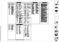
LIST OF DRAWINGSContract drawings are as follows:NAVFAC SHEETDWG NO. NO. TITLE60010317 T-1 Title Sheet, Index of Drawings, Sitemap60010318 LS-1 Life Safety Plan and Code Analysis60010318A FP-160010318B FA-160010318C C-160010318D C-2Fire Sprinkler PlanFire Alarm PlanSite PlanDetails60010319 D-1 Demolition First Floor Plan60010320 D-2 Demolition Second floor Plan and Enlarged Plan60010321 D-3 Demolition First Floor Reflected Ceiling Plan60010322 A-1 Renovated First Floor Plan60010323 A-2 Renovated Second Floor and Enlarged Plan60010324 A-3 Renovated First Floor Reflected Ceiling Plan60010325 A-4 Interior Elevations and Enlarged Plans60010326 A-5 Interior Elevations and Enlarged Plans60010327 A-6 Building Sections60010328 A-7 Details and Schedules60010329 P-1 Plumbing Legend, Notes, and Schedules60010330 P-2 Plumbibg Toilet room Plans60010331 M-1 Mechanical Demolition Plans60010332 M-2 Mechanical New work Plan60010333 E-0 Electrical Legend and Details60010334 E-1 Electrical Demolition Reflected Ceiling Plan60010335 E-2 New Work Plan60010336 E-3 Panel and Light Fixture Schedule60010337 E-4 Electrical Site Plan for Temporary Trailers
Repairs to Covered Storage Building AS-4171 05110173SECTION 01 11 00SUMMARY OF WORK09/08PART 1GENERAL1.1 WORK COVERED BY CONTRACT DOCUMENTS1.1.1 Project DescriptionThe work includes the repair of covered storage Building AS4171. Theproject will include demolition, lead abatement, new construction,plumbing, electrical, and associated finishes, which include new VCTfloors, paint, new acoustical ceiling, and incidental related work.1.1.2 LocationThe work shall be located at the Marine Corps Air Station, New River,Jacksonville, North Carolina approximately as shown. The exact locationwill be indicated by the Contracting Officer.1.2 EXISTING WORKIn addition to "FAR 52.236-9, Protection of Existing Vegetation,Structures, Equipment, Utilities, and Improvements":a. Remove or alter existing work in such a manner as to preventinjury or damage to any portions of the existing work which remain.b. Repair or replace portions of existing work which have beenaltered during construction operations to match existing oradjoining work, as approved by the Contracting Officer. At thecompletion of operations, existing work shall be in a conditionequal to or better than that which existed before new work started.1.3 LOCATION OF UNDERGROUND FACILITIESThe Contractor will be responsible for obtaining the services of aprofessional utility locator to scan the construction site withelectromagnetic or sonic equipment, and mark the surface of the groundwhere existing underground utilities are discovered. Verify the elevationsof existing piping, utilities, and any type of underground obstruction notindicated or specified to be removed but indicated or discovered duringscanning in locations to be traversed by piping, ducts, and other work tobe installed. Verify elevations before installing new work closer thannearest manhole or other structure at which an adjustment in grade can bemade.1.3.1 Notification Prior to ExcavationNotify the Contracting Officer 48 hours prior to starting excavation workin order to permit making arrangements with public works personnel to scanthe area for unmarked utilities. Obtain station digging permits prior tostarting excavation work.SECTION 01 11 00 Page 1
Repairs to Covered Storage Building AS-4171 05110173PART 2PRODUCTSNot used.PART 3EXECUTIONNot used.-- End of Section --SECTION 01 11 00 Page 2
Repairs to Covered Storage Building AS-4171 05110173SECTION 01 12 00CUTTING AND PATCHING01/07PART 1GENERAL1.1 CUTTINGShall be done by sawing along straight lines. The amount cut out shall bethe minimum necessary to accommodate the new work. No flame cutting willbe permitted without written permission of the Officer in Charge ofConstruction.1.2 HOLESShall be rotary drilled. The size shall be the minimum necessary toaccommodate the new work.1.3 PATCHINGShall be done with materials which match the existing in color, quality andsurface texture when finished.PART 2PRODUCTSNot used.PART 3EXECUTIONNot used.-- End of Section --SECTION 01 12 00 Page 1
Repairs to Covered Storage Building AS-4171 05110173SECTION 01 14 00WORK RESTRICTIONS01/07PART 1GENERAL1.1 CONTRACTOR ACCESS AND USE OF PREMISES1.1.1 Station RegulationsEnsure that Contractor personnel employed on the Station become familiarwith and obey Station regulations. Keep within the limits of the work andavenues of ingress and egress as directed. Do not enter restricted areasunless required to do so and until cleared for such entry. Wear hard hatsin designated areas. Do not enter any restricted aras unless required todo so and until cleared for such entry. The Contractor's equipment shallbe conspicuously marked for identification.1.1.2 Working HoursRegular working hours shall consist of an eight and one-half hour periodestablished by the Contracting Officer, Monday through Friday, excludingGovernment holidays.1.1.3 Work Outside Regular HoursWork outside regular working hours requires Contracting Officer approval.Provide written request at least 15 calendar days prior to such work toallow arrangements to be made by the Government for inspecting the work inprogress. During periods of darkness, the different parts of the workshall be lighted in a manner approved by the Contracting Officer.1.1.4 Occupied and Existing BuildingsThe Contractor shall be working in an existing building which is occupied.Do not enter the building without prior approval of the Contracting Officer.The existing buildings and their contents shall be kept secure at alltimes. Provide temporary closures as required to maintain security asdirected by the Contracting Officer.1.1.5 Utility Cutovers and Interruptionsa. Make utility cutovers and interruptions after normal working hoursor on Saturdays, Sundays, and Government holidays. Conform toprocedures required in the paragraph "Work Outside Regular Hours."b. Ensure that new utility lines are complete, except for theconnection, before interrupting existing service.c. Interruption to water, sanitary sewer, storm sewer, telephoneservice, electric service, air conditioning, heating, fire alarm,compressed air, shall be considered utility cutovers pursuant tothe paragraph entitled "Work Outside Regular Hours."SECTION 01 14 00 Page 1
Repairs to Covered Storage Building AS-4171 05110173d. Operation of Station Utilities: The Contractor shall not operatenor disturb the setting of control devices in the stationutilities system, including water, sewer, electrical, and steamservices. The Government will operate the control devices asrequired for normal conduct of the work. The Contractor shallnotify the Contracting Officer giving reasonable advance noticewhen such operation is required.PART 2PRODUCTSNot used.PART 3EXECUTIONNot used.-- End of Section --SECTION 01 14 00 Page 2
Repairs to Covered Storage Building AS-4171 05110173SECTION 01 20 00PRICE AND PAYMENT PROCEDURES04/12PART 1GENERAL1.1 REFERENCESThe publications listed below form a part of this specification to theextent referenced. The publications are referred to in the text by thebasic designation only.U.S. ARMY CORPS OF ENGINEERS (USACE)COE EP-1110-1-8(1995) Construction Equipment Ownershipand Operating Expense Schedule1.2 SUBMITTALSSubmit the following in accordance with Section 01 33 00,"SubmittalProcedures."SD-01 Preconstruction SubmittalsSchedule of prices1.3 SCHEDULE OF PRICES1.3.1 Data RequiredWithin 15 calendar days of notice of award, prepare and deliver toContracting Officer a schedule of prices (construction contract) on theforms furnished by the Government. Provide a detailed breakdown of thecontract price, giving quantities for each of the various kinds of work,unit prices, and extended prices therefor. Schedule of prices shall beseparated by individual building numbers with subtotals for each building.1.3.2 Schedule InstructionsPayments will not be made until the schedule of prices has been submittedto and approved by the Contracting Officer. Identify the cost for sitework, and include incidental work to the 5 foot line. Identify costs forthe building(s), and include work out to the 5 foot line. Workout to the 5foot line shall include construction encompassed within a theoretical line5 feet from the face of exterior walls and shall include attendantconstruction, such as cooling towers, placed beyond the 5 foot line.1.4 CONTRACT MODIFICATIONSIn conjunction with the Contract Clause "DFARS 252.236-7000, ModificationProposals-Price Breakdown," and where actual ownership and operating costsof construction equipment cannot be determined from Contractor accountingrecords, equipment use rates shall be based upon the applicable provisionsof the COE EP-1110-1-8.SECTION 01 20 00 Page 1
Repairs to Covered Storage Building AS-4171 051101731.5 CONTRACTOR'S PAYMENT REQUEST1.5.1 Proper Payment RequestA proper request for payment/invoice shall comply with all requirementsspecified in this Section and the contract payment clauses. If any invoicedoes not comply with these requirements, it shall be returned with astatement of the reasons why it was not a proper invoice. A proper paymentrequest/invoice includes the following information, completed forms, andnumber of copies indicated. Upon request, the Contracting Officer willfurnish copies of Government forms.a. Contractor's Invoice on NAVFAC Form 7300/30, which shall show thebasis for arriving at the amount of the invoice. Submit oneoriginal and two copies.b. Contractor's Monthly Estimate for Voucher (LANTNAVFACENGCOM Form4-4330/110. Submit original and two copies.c. Payment Certification. Furnish as specified in "FAR Clause52.232-5 (c) Payments under Fixed-Price Construction Contracts."Submit one original.d. QC Invoice Certification. Furnish as specified in Section 01 45 10,"Quality Control." Submit one original.1.5.1.1 Progress PaymentsIn addition to the requirements stated in Paragraph 1.5.1, "Proper PaymentRequest" above, the Contractor's request for progress payments shallinclude the following:a. Updated Progress Schedule: Furnish an updated progress scheduleas specified in contract clause FAR 52.236-15 "Schedules forConstruction Contracts" and Section 01 32 16, "ConstructionProgress Documentation." Submit one copy.1.5.1.2 Final PaymentsThe request for final payment is submitted after completion and acceptanceof all work and all other requirements of the contract. Before submittingthe final invoice the Contractor shall meet with the appropriate Governmentrepresentatives to determine the final invoice amount, including theassessment of liquidated damages, if any, and to make sure the finalrelease is complete and accurate. In addition to the requirements inParagraph 1.5.1, "Proper Payment Request" above, the Contractor's requestfor final payment shall include the following:a. A final release executed on the standard form provided by theContracting Officer. Submit two originals with final paymentrequest.b. NC Tax certified statement and report for the prime and eachsubcontractor (FAR 52.229-7). Submit two copies.c. As-built drawings (if applicable).d. Warranties (if applicable).SECTION 01 20 00 Page 2
Repairs to Covered Storage Building AS-4171 05110173e. O&M manuals (if applicable).f. Final payrolls (FAR 52.222-6).g. A release for an assignment of claims (if applicable). Submitthree originals.1.5.2 Procedures for Submitting Payment Requesta. The Contractor may submit only one invoice for payment each monthas the work progresses.b. The invoice shall be delivered to the ROICC Office, AdministrativeBranch, between five calendar days before and five calendar daysafter the contract award date. Invoices received outside thisschedule shall be returned to the Contractor unprocessed. TheContractor will have to wait until the following month to submittheir next invoice.c. Invoices shall be delivered during normal work hours from 7:30 AMup to 4:00 PM (EST), Monday through Friday, excluding holidays.1.6 PAYMENTS TO THE CONTRACTORPayments will be made on submission of a proper payment request/invoice bythe Contractor.1.6.1 Obligation of Government PaymentsThe obligation of the Government to make payments required under theprovisions of this contract will, at the discretion of the ContractingOfficer, be subject to the following:a. Reasonable retention and/or deductions due to defects in materialor workmanship; potential liquidated damages; and/or failure tocomply with any other requirements of the contract.b. Claims which the Government may have against the Contractor underor in connection with this contract; andc. Unless otherwise adjusted, repayment to the Government upon demandfor overpayments made to the Contractor.d. Failure to provide up to date record drawings not current asstated in Contract Clause "FAC 5252.236-9310, Record Drawings"; NCState tax certified statement and report in accordance with FAR52.229-2; labor payrolls in accordance with FAR 52.222-6; as-builtdrawings in accordance with Section 01 45 10, "Quality Control";warranties and O&M manuals; and any other requirements in thecontract.1.6.2 Payment for Onsite and Offsite MaterialsProgress payments may be made to the contractor for materials delivered onthe site, for materials stored off construction sites, or materials thatare in transit to the construction sites under the following conditions:a. FAR 52.232-5(b) Payments Under Fixed Price Construction Contracts.SECTION 01 20 00 Page 3
Repairs to Covered Storage Building AS-4171 05110173b. Materials delivered on the site but not installed, includingcompleted preparatory work, and off- site materials to beconsidered for progress payment shall be major high cost, longlead, special order, or specialty items, not susceptible todeterioration or physical damage in storage or in transit to theconstruction site. Examples of materials acceptable for paymentconsiderations include, but are not limited to, structural steel,non-magnetic steel, non-magnetic aggregate, equipment, machinery,large pipe and fittings, precast/ prestressed concrete products,plastic lumber (e.g. fender piles/ curbs), and high-voltageelectrical cable. Materials no acceptable for payment includeconsumable materials such as nails, fasteners, conduits, gypsumboard, glass, insulation, and wall coverings.c. Materials to be considered for progress payment prior toinstallation shall be specifically and separately identified inthe Contractor's estimates of work submitted for the ContractingOfficer's approval in accordance with Earned Value Reportrequirement of this contract. Requests for progress paymentconsiderations for such items shall be supported by documentsestablishing their value and that the title requirements of theclause at FAR 52.232-5 have been met.d. Materials are adequately insured and protected from theft andexposure.e. Provide a written consent from the surety company with eachpayment request for offsite materials.f. Materials to be considered for progress payments prior toinstallation shall be stored in the Continental United States.PART 2PRODUCTSNot used.PART 3EXECUTIONNot used.-- End of Section --SECTION 01 20 00 Page 4
Repairs to Covered Storage Building AS-4171 05110173SECTION 01 30 00ADMINISTRATIVE REQUIREMENTS03/12PART 1GENERAL1.1 SUBMITTALSSubmit the following in accordance with the Section 01 33 00, "SubmittalProcedures."SD-01 Preconstruction SubmittalsList of contact personnel1.2 MINIMUM INSURANCE REQUIREMENTSProcure and maintain during the entire period of performance under thiscontract the following minimum insurance coverage:a. Comprehensive general liability: $500,000 per occurrenceb. Automobile liability: $200,000 per person, $500,000 peroccurrence, $20,000 per occurrence for property damagec. Workmen's compensation as required by Federal and State workers'compensation and occupational disease laws,d. Employer's liability coverage of $100,000, except in States whereworkers compensation may not be written by private carriers,e. Others as required by State law.1.3 ELECTRONIC MAIL (EMAIL)a. The Contractor is required to establish and maintain electronicmail (email) capability along with the capability to open variouselectronic attachments in Microsoft, Adobe Acrobat, and othersimilar formats.b. Within 10 days after contract award; the Contractor shall providethe Contracting Officer a single (only one) email address for theROICC office to send communications related to this contractcorrespondence. The ROICC office may also use email to notify theContractor of base access conditions when emergency conditionswarrant, such as hurricanes, terrorist threats, etc.c. Multiple email addresses are not authorized.d. It is the Contractor's responsibility to make timely distributionof all ROICC email within its own organization, including fieldoffice(s).e. The Contractor shall promptly notify the Contracting Officer, inwriting, of any changes to their email address.SECTION 01 30 00 Page 1
Repairs to Covered Storage Building AS-4171 051101731.4 CONTRACTOR PERSONNEL REQUIREMENTS1.4.1 Subcontractors and PersonnelFurnish a list of contact personnel of the Contractor and subcontractorsincluding addresses and telephone numbers for use in the event of anemergency. As changes occur and additional information becomes available,correct and change the information contained in previous lists.1.4.2 Identification BadgesIdentification badges will be furnished without charge. Application forand use of badges will be as directed below. Immediately report instancesof lost or stolen badges to the Contracting Officer. Employees arerequired to resubmit a complete 50 state criminal records check in order torenew their contractor badge.1.4.3 Business Access Security Requirements1.4.3.1 Business Access DefinitionContractor/subcontractor employees requiring installation access to MCB,Camp Lejeune or MCAS New River, N.C. must obtain a Business AccessIdentification Badge for that particular installation. Regularly scheduleddelivery personnel, to include FEDEX, UPS, Pick-up and deliveries, should,also, follow the Business Access guidelines described below. Personnelrequiring Business Access Identification Badges shall submit alldocumentation listed below. Badges are not required if the contractedposition requires the employee to obtain a Common Access Card (CAC) whichwill be identified separately within the Government contract.1.4.3.2 Installation Security Access RequirementsContractor shall accomplish the security requirements below within 10 daysafter award or prior to performance under the contract.1.4.3.3 Business Access Identification Badge RequirementIn order to obtain a Business Access Identification Badge for access toMCB, Camp Lejeune, and satellite activities, or MCAS New River, NC, allpersonnel providing services under this contract shall be required topresent the documentation below to the following offices, as applicable:MCB, Camp Lejeune, NC and its satellite activities. Report as follows:1. Identification Card Center, 60 Molly Pitcher Road for badge(910-450-8444).MCAS New River, NC. Report as follows:1. Pass and Identification Office, Bldg AS-187 for badge(910-449-7695) and vehicle pass (910-449-5513).1.4.3.4 Proof of Employee Citizenship or Legal Alien StatusEmployers may participate in the E-verify program (1-888-464-4218,www.DHS.gov/e-verify) allowing U.S. employers to verify name, DOB, and SSNalong with immigration information for non-citizens, against federalSECTION 01 30 00 Page 2
Repairs to Covered Storage Building AS-4171 05110173databases in order to verify the employment eligibility of both citizensand non-citizen new hires.1.4.3.5 Proof of Criminal Records CheckCommercial and contract employees must provide proof a complete 50 statecriminal records check on an annual basis. The record check may beobtained from any of the following Internet investigative services: Kroll(former Infolink Screening Services) at www.kroll.com, Castle Branch atwww.castlebranch.com, or any other investigative services company thatprovides records checks for all 50 states. These services also validatesocial security card numbers. All criminal history checks must becompleted no more than 30 days prior to start date of contract. (Note:These Internet screening services are listed as possible sources forobtaining a criminal background check. The United States government andthe United States Marine Corps do not endorse nor are they affiliated withany of these services).1.4.3.6 Letter Provided By Contracting Officer Indicating ContractLetter provided by Contracting Officer indicating contract, contract periodand prime contractor. Proof of employment on a valid Government contract(e.g., a letter on company letterhead from the prime contractor includingcontract number and term).1.4.3.7 Photo IDValid state or federal issued picture identification card. Acceptabledocuments include state drivers license, DMV issued photo identification,or alien registration card.1.4.3.8 National Crime Investigation Center (NCIC) CheckProvost Marshals are authorized to conduct a national crime informationcenter (NCIC) check of all persons entering the installation, if/whereapplicable, the NCIC check may include drivers's license query, wants andwarrants, and criminal history.1.4.4 Denial of AccessInstallation access shall be denied if it is determined that an employee:a. Is on the National Terrorist Watch Listb. Is illegally present in the United States.c. Is subject to an outstanding warrant.d. Has knowingly submitted an employment questionnaire with false orfraudulent information.e. Has been issued a debarment order and is currently banned frommilitary installations.f. Is a Registered Sexual Offender.g. Has been convicted of a felony or a drug crime within the pastfive years.SECTION 01 30 00 Page 3
Repairs to Covered Storage Building AS-4171 05110173h. Individuals who have received a DUI/DWI in the last year may beallowed access to the installation, but will not be permitted todrive on the installation.i. Any reason the Installation Commander deems reasonable for thegood order and discipline.1.4.5 Appeal ProcessAll appeals should be directed to the Base Inspector's Office for anyindividual that has been denied access to the Base.1.4.6 Display of Badges<strong>Contractors</strong>/subcontractors shall prominently display their badges on theirperson at all times. Upon completion/termination of this contract or anindividual's employment, the Contractor shall collect and turn in to thePass & ID Office all badges. If the Contactor fails to obtain theemployee's badge, the Pass & ID Office will be notified within 24 hours.Immediately report instances of lost or stolen badges to the ContractingOfficer.1.4.7 Contractor and Subcontractor Vehicle RequirementsEach vehicle to be used in contract performance shall show the Contractor'sor subcontractor's name so that it is clearly visible and shall alwaysdisplay a valid state license plate and safety inspection sticker. Toobtain a vehicle decal, which will be valid for one year or contractperiod, whichever is shorter, Contractor or subcontractor vehicle operatorsshall provide to the Vehicle Registration Office, 60 Molly Pitcher Road(910-451-1158) or to MCAS, Building AS-187 (910-449-5513) for vehicle decal:a. An installation sponsor request forwarded to provost Marshallofficeb. A valid form of Federal or state government I.D.c. If driving a motor vehicle, a valid driver's license, vehicleregistration and proof of insuranceUpon completion/termination of this contract or an individual's employment,the Contractor shall collect and turn in to Vehicle Registration allGovernment vehicle decals. If any are not collected, the Contractor shallnotify the Vehicle Registration Office within 24 hours.1.4.8 Security ChecksContractor personnel and vehicles shall only be present in locationsrelevant to contract performance. All Contractor personnel entering thebase shall conform to all Government regulations and are subject to suchchecks as may be deemed necessary to ensure that violations do not occur.Employees shall not be permitted on base when such a check reveals thattheir presence would be detrimental to the security of the base. Subjectto security regulations, the Government will allow access to an area forservicing equipment and/or performing required services. Upon request, theContractor shall submit to the Contracting Officer questionnaires and otherforms as may be required for security purposes.SECTION 01 30 00 Page 4
Repairs to Covered Storage Building AS-4171 051101731.4.9 Subcontractor Special Requirements1.4.9.1 Asbestos Containing MaterialAll contract requirements of Section 02 82 17, "Removal and Disposal ofNon-Regulated Asbestos Containing Materials" assigned to the PrivateQualified Person (PQP) shall be accomplished directly by a first tiersubcontractor.1.4.9.2 Telecommunication and High Voltage WorkWhen telecommunications and high voltage work is required, all workassociated with telecommunications and high voltage shall be accomplishedby a first tier subcontractor. The contractor must possess a valid NorthCarolina Public Utility - Electrical, contractor's license and be insuredto do such work in the State of North Carolina.1.5 DISCLOSURE OF INFORMATIONContactor shall comply as follows:(a) The Contractor shall not release to anyone outside the Contractor'sorganization any unclassified information, regardless of medium (e.g.,film, tape, document), pertaining to any part of this contract or anyprogram related to this contact, unless -(1) The Contracting Officer has given prior written approval; or(2) The information is otherwise in th public domain before thedate of release.(b) Requests for approval shall identify the specific information to bereleased, the medium to be used, and the purpose for the release. TheContractor shall submit its request to the Contracting Officer at least45 days before the proposed date for release.(c) The Contractor agrees to include a similar requirement in eachsubcontract under this contract. Subcontractors shall submit requestsfor authorization to release through the prime contractor to theContracting Officer.1.6 SUPERVISIONHave at least one qualified supervisor capable of reading, writing, andconversing fluently in the English language on the job site during workinghours. In addition, if a Quality Control (CQ) representative is requiredon the contract, then that individual shall also have fluent Englishcommunication skills.NOTE: If training and experience requirements of Section 01 45 10,"Quality Control" and 01 35 29, "Safety and Occupational HealthRequirements" have been met the supervisor may also serve as QC Manager andSite Safety and Health Officer (SSHO).1.7 PRECONSTRUCTION CONFERENCEAfter award of the contract but prior to commencement of any work at thesite, meet with the Contracting Officer to discuss and develop a mutualunderstanding relative to the administration of the value engineering andSECTION 01 30 00 Page 5
Repairs to Covered Storage Building AS-4171 05110173safety program, preparation of the schedule of prices, shop drawings, andother submittals, scheduling programming, and prosecution of the work.Major subcontractors who will engage in the work shall also attend.PART 2PRODUCTSNot used.PART 3EXECUTIONNot used.-- End of Section --SECTION 01 30 00 Page 6
Repairs to Covered Storage Building AS-4171 05110173SECTION 01 32 16CONSTRUCTION PROGRESS DOCUMENTATION04/12PART 1GENERAL1.1 SUBMITTALSSubmit the following in accordance with Section 01 33 00, "SubmittalProcedures."SD-01 Preconstruction SubmittalsConstruction scheduleEquipment delivery schedule1.2 CONSTRUCTION SCHEDULEWithin 21 days after receipt of the Notice of Award, prepare and submit tothe Contracting Officer for approval a Critical Path Method (CPM), NetworkSchedule in accordance with the terms in Contract Clause "FAR 52.236-15,Schedules for Construction Contracts," except as modified in thiscontract. Primavera P6 will be utilized to produce and update all progressschedules.1.3 EQUIPMENT DELIVERY SCHEDULE1.3.1 Initial ScheduleWithin 30 calendar days after approval of the proposed constructionschedule, submit for Contracting Officer approval a schedule showingprocurement plans for materials, plant, and equipment. Submit in theformat and content as prescribed by the Contracting Officer, and include asa minimum the following information:a. Description.b. Date of the purchase order.c. Promised shipping date.d. Name of the manufacturer or supplier.e. Date delivery is expected.f. Date the material or equipment is required, according to thecurrent construction schedule.1.4 NETWORK ANALYSIS SYSTEM (NAS)The Contractor shall use the critical path method (CPM) to schedule andcontrol construction activities. The Network shall have a minimum of 25activities and a maximum of 35 activities. The schedule shall identify asa minimum:SECTION 01 32 16 Page 1
Repairs to Covered Storage Building AS-4171 05110173a. Construction time for all major systems and components;b. Major equipment lead time.1.4.1 CPM Submittals and ProceduresThe Contractor shall use the critical path method (CPM) to schedule andcontrol project activities. Project schedules shall be prepared andmaintained using Primavera P6, Primavera SureTrak or current mandatedscheduling program. Save files in Concentric P6 or current mandatedscheduling program file format, compatible with the Governments version ofthe scheduling program. The network analysis system shall be kept current,with changes made to reflect the actual progress and status of theconstruction.1.5 UPDATED SCHEDULESUpdate the construction schedule and equipment delivery schedule at monthlyintervals or when schedule has been revised. Reflect any changes occurringsince the last update. Submit copies of the purchase orders andconfirmation of the delivery dates as directed.PART 2PRODUCTSNot used.PART 3EXECUTIONNot used.-- End of Section --SECTION 01 32 16 Page 2
Repairs to Covered Storage Building AS-4171 05110173SECTION 01 33 00SUBMITTAL PROCEDURES12/10PART 1GENERAL1.1 SUMMARY1.1.1 Government-Furnished InformationSubmittal register will be delivered to the contractor in hard copyformat. Register will have the following fields completed, to the extentthat will be required by the Government during subsequent usage.Column (c): Lists specification section in which submittal is required.Column (d): Lists each submittal description (SD No. and type, e.g.SD-04 Drawings) required in each specification section.Column (e): Lists one principal paragraph in specification sectionwhere a material or product is specified. This listing is only tofacilitate locating submitted requirements. Do not consider entries incolumn (e) as limiting project requirements.Column (f): Indicate approving authority for each submittal. TheContracting Officer is approving authority for all submittals.1.2 DEFINITIONS1.2.1 SubmittalShop drawings, product data, samples, and administrative submittalspresented for review and approval. Contract Clauses "FAR 52.236-5,Material and Workmanship," paragraph (b) and "FAR 52.236-21, <strong>Specifications</strong>and Drawings for Construction," paragraphs (d), (e), and (f) apply to all"submittals."1.2.2 Types of SubmittalsAll submittals are classified as indicated in paragraph "SubmittalDescriptions (SD)". Submittals also are grouped as follows:a. Shop drawings: As used in this section, drawings, schedules,diagrams, and other data prepared specifically for this contract,by contractor or through contractor by way of subcontractor,manufacturer, supplier, distributor, or other lower tiercontractor, to illustrate portion of work.b. Product data: Preprinted material such as illustrations, standardschedules, performance charts, instructions, brochures, diagrams,manufacturer's descriptive literature, catalog data, and otherdata to illustrate portion of work, but not prepared exclusivelyfor this contract.c. Samples: Physical examples of products, materials, equipment,SECTION 01 33 00 Page 1
Repairs to Covered Storage Building AS-4171 05110173assemblies, or workmanship that are physically identical toportion of work, illustrating portion of work or establishingstandards for evaluating appearance of finished work or both.d. Administrative submittals: Data presented for reviews andapproval to ensure that administrative requirements of project areadequately met but not to ensure directly that work is inaccordance with design concept and in compliance with contractdocuments.1.2.3 Submittal Descriptions (SD)SD-01 Preconstruction SubmittalsCertificates of insuranceSurety bondsList of proposed subcontractorsList of proposed productsConstruction Progress ScheduleSubmittal scheduleSchedule of valuesHealth and safety planWork planQuality control planEnvironmental protection planSD-02 Shop DrawingsDrawings, diagrams and schedules specifically prepared to illustrate someportion of the work.Diagrams and instructions from a manufacturer or fabricator for use inproducing the product and as aids to the contractor for integrating theproduct or system into the project.Drawings prepared by or for the contractor to show how multiple systems andinterdisciplinary work will be coordinated.SD-03 Product DataCatalog cuts, illustrations, schedules, diagrams, performance charts,instructions and brochures illustrating size, physical appearance and othercharacteristics of materials or equipment for some portion of the work.Samples of warranty language when the contract requires extended productwarranties.SD-04 SamplesPhysical examples of materials, equipment or workmanship that illustratefunctional and aesthetic characteristics of a material or product andestablish standards by which the work can be judged.Color samples from the manufacturer's standard line (or custom colorsamples if specified) to be used in selecting or approving colors for theproject.Field samples and mock-ups constructed on the project site establishstandards by which the ensuring work can be judged. Includes assemblies orSECTION 01 33 00 Page 2
Repairs to Covered Storage Building AS-4171 05110173portions of assemblies which are to be incorporated into the project andthose which will be removed at conclusion of the work.SD-05 Design DataCalculations, mix designs, analyses or other data pertaining to a part ofwork.SD-06 Test ReportsReport signed by authorized official of testing laboratory that a material,product or system identical to the material, product or system to beprovided has been tested in accord with specified requirements. (Testingmust have been within three years of date of contract award for theproject.)Report which includes findings of a test required to be performed by thecontractor on an actual portion of the work or prototype prepared for theproject before shipment to job site.Report which includes finding of a test made at the job site or on sampletaken from the job site, on portion of work during or after installation.Investigation reportsDaily checklistsFinal acceptance test and operational test procedureSD-07 CertificatesStatements signed by responsible officials of manufacturer of product,system or material attesting that product, system or material meetsspecification requirements. Must be dated after award of project contractand clearly name the project.Document required of Contractor, or of a supplier, installer orsubcontractor through Contractor, the purpose of which is to furtherquality of orderly progression of a portion of the work by documentingprocedures, acceptability of methods or personnel qualifications.Confined space entry permits.SD-08 Manufacturer's InstructionsPreprinted material describing installation of a product, system ormaterial, including special notices and Material Safety Data sheetsconcerning impedances, hazards and safety precautions.SD-09 Manufacturer's Field ReportsDocumentation of the testing and verification actions taken bymanufacturer's representative to confirm compliance with manufacturer'sstandards or instructions.Factory test reports.SD-10 Operation and Maintenance DataSECTION 01 33 00 Page 3
Repairs to Covered Storage Building AS-4171 05110173Data intended to be incorporated in operations and maintenance manuals.SD-11 Closeout SubmittalsDocumentation to record compliance with technical or administrativerequirements or to establish an administrative mechanism.As-built drawingsSpecial warrantiesPosted operating instructionsTraining plan1.2.4 Approving AuthorityPerson authorized to approve submittal.1.2.5 WorkAs used in this section, on- and off-site construction required by contractdocuments, including labor necessary to produce construction and materials,products, equipment, and systems incorporated or to be incorporated in suchconstruction.1.3 SUBMITTALSSubmit the following in accordance with the requirements of this section.SD-11 Closeout SubmittalsSubmittal registerComplete Submittal Package 1 CD1.4 USE OF SUBMITTAL REGISTERPrepare and maintain submittal register, as the work progresses. Use thehard copy submittal register furnished by the Government or other approvedformat. Do not change data which is output in columns (c), (d), (e), and(f) as delivered by government; retain data which is output in columns (a),(g), (h), and (i) as approved.1.4.1 Submittal RegisterSubmit submittal register as a hard copy. Submit with quality control planand project schedule required by Section 01 45 10, "Quality Control" andSection 01 32 16, "Construction Progress Documentation." Do not changedata in columns (c), (d), (e), and (f) as delivered by the government.Verify that all submittals required for project are listed and add missingsubmittals. Complete the following on the register:Column (a) Activity Number: Activity number from the project schedule.Column (g) Contractor Submit Date: Scheduled date for approvingauthority to receive submittals.Column (h) Contractor Approval Date: Date contractor needs approval ofSECTION 01 33 00 Page 4
Repairs to Covered Storage Building AS-4171 05110173submittal.Column (i) Contractor Material: Date that contractor needs materialdelivered to contractor control.1.4.2 Contractor Use of Submittal RegisterUpdate the following fields in the government-furnished submittal register.Column (b) Transmittal Number: Contractor assigned list of consecutivenumbers.Column (j) Action Code (k): Date of action used to record contractor'sreview when forwarding submittals to QC.Column (l) List date of submittal transmission.Column (q) List date approval received.1.4.3 Approving Authority Use of Submittal RegisterUpdate the following fields in the government-furnished submittal register.Column (b).Column (l) List date of submittal receipt.Column (m) through (p).Column (q) List date returned to contractor.1.4.4 Contractor Action Code and Action CodeEntries used will be as follows (others may be prescribed by TransmittalForm):NR - Not ReceivedAN - Approved as notedA - ApprovedRR - Disapproved, Revise, and Resubmit1.4.5 Copies Delivered to the GovernmentDeliver one copy of submitted register updated by contractor to governmentwith each invoice request.1.5 PROCEDURES FOR SUBMITTALS1.5.1 Reviewing, Certifying, Approving AuthorityQC organization shall be responsible for reviewing and certifying thatsubmittals are in compliance with contract requirements. The ContractingOfficer is the approving authority for all submittals.SECTION 01 33 00 Page 5
Repairs to Covered Storage Building AS-4171 051101731.5.2 Constraintsa. Submittals listed or specified in this contract shall conform toprovisions of this section, unless explicitly stated otherwise.b. Submittals shall be complete for each definable feature of work;components of definable feature interrelated as a system shall besubmitted at same time.c. When acceptability of a submittal is dependent on conditions,items, or materials included in separate subsequent submittals,submittal will be returned without review.d. Approval of a separate material, product, or component does notimply approval of assembly in which item functions.1.5.3 Schedulinga. Coordinate scheduling, sequencing, preparing and processing ofsubmittals with performance of work so that work will not bedelayed by submittal processing. Allow for potential requirementsto resubmit.b. Except as specified otherwise, allow review period, beginning withreceipt by approving authority, that includes at least 15 workingdays for submittals for QC manager approval and 20 working daysfor submittals for contracting officer approval. Period of reviewfor submittals with contracting officer approval begins whenGovernment receives submittal from QC organization. Period ofreview for each resubmittal is the same as for initial submittal.c. For submittals requiring review by fire protection engineer, allowreview period, beginning when government receives submittal fromQC organization, of 45 working days for return of submittal to thecontractor. Period of review for each resubmittal is the same asfor initial submittal.1.5.4 VariationsVariations from contract requirements require Government approval pursuantto contract Clause entitled "FAR 52.236-21, <strong>Specifications</strong> and Drawings forConstruction" and will be considered where advantageous to government.1.5.4.1 Considering VariationsDiscussion with contracting officer prior to submission, will help ensurefunctional and quality requirements are met and minimize rejections andresubmittals. When contemplating a variation which results in lower cost,consider submission of the variation as a Value Engineering Change Proposal(VECP).1.5.4.2 Proposing VariationsWhen proposing variation, deliver written request to the contractingofficer, with documentation of the nature and features of the variation andwhy the variation is desirable and beneficial to government. If lower costis a benefit, also include an estimate of the cost saving. In addition todocumentation required for variation, include the submittals required forthe item. Clearly mark the proposed variation in all documentation.SECTION 01 33 00 Page 6
Repairs to Covered Storage Building AS-4171 051101731.5.4.3 Warranting That Variation Are CompatibleWhen delivering a variation for approval, contractor warrants that thiscontract has been reviewed to establish that the variation, ifincorporated, will be compatible with other elements of work.1.5.4.4 Review Schedule Is ModifiedIn addition to normal submittal review period, a period of 10 working dayswill be allowed for consideration by the Government of submittals withvariations.1.5.5 Contractor's Responsibilitiesa. Determine and verify field measurements, materials, fieldconstruction criteria; review each submittal; and check andcoordinate each submittal with requirements of the work andcontract documents.b. Transmit submittals to QC organization in accordance with scheduleon approved Submittal Register, and to prevent delays in the work,delays to government, or delays to separate contractors.c. Advise contracting officer of variation, as required by paragraphentitled "Variations."d. Correct and resubmit submittal as directed by approvingauthority. When resubmitting disapproved transmittals ortransmittals noted for resubmittal, the contractor shall providecopy of that previously submitted transmittal including allreviewer comments for use by approving authority. Direct specificattention in writing or on resubmitted submittal, to revisions notrequested by approving authority on previous submissions.e. Furnish additional copies of submittal when requested bycontracting officer, to a limit of 20 copies per submittal.f. Complete work which must be accomplished as basis of a submittalin time to allow submittal to occur as scheduled.g. Ensure no work has begun until submittals for that work have beenreturned as "approved," or "approved as noted", except to theextent that a portion of work must be accomplished as basis ofsubmittal.1.5.6 QC Organization Responsibilitiesa. Note date on which submittal was received from contractor on eachsubmittal.b. Review each submittal; and check and coordinate each submittalwith requirements of work and contract documents.c. Review submittals for conformance with project design concepts andcompliance with contract documents.d. Act on submittals, determining appropriate action based on QCorganization's review of submittal.SECTION 01 33 00 Page 7
Repairs to Covered Storage Building AS-4171 05110173(1) When QC manager is approving authority, take appropriateaction on submittal from the possible actions defined in paragraphentitled, "Actions Possible."(2) When contracting officer is approving authority or whenvariation has been proposed, forward submittal to Government withcertifying statement or return submittal marked "not reviewed" or"revise and resubmit" as appropriate. The QC organization'sreview of submittal determines appropriate action.e. Ensure that material is clearly legible.f. Stamp each sheet of each submittal with QC certifying statement orapproving statement, except that data submitted in bound volume oron one sheet printed on two sides may be stamped on the front ofthe first sheet only.(1) When approving authority is contracting officer, QCorganization will certify submittals forwarded to contractingofficer with the following certifying statement:"I hereby certify that the (equipment) (material) (article) shown andmarked in this submittal is that proposed to be incorporated withcontract Number N40085-11-B-0173, is in compliance with thecontract drawings and specification, can be installed in theallocated spaces, and is submitted for Government approval.Certified by Submittal Reviewer _____________________, Date _______(Signature when applicable)Certified by QC manager _____________________________, Date ______"(Signature)g. Sign certifying statement or approval statement. The personsigning certifying statements shall be QC organization memberdesignated in the approved QC plan. The signatures shall be inoriginal ink. Stamped signatures are not acceptable.h. Update submittal register as submittal actions occur and maintainthe submittal register at project site until final acceptance ofall work by contracting officer.i. Retain a copy of approved submittals at project site, includingcontractor's copy of approved samples.1.5.7 Government's ResponsibilitiesWhen approving authority is contracting Officer, the Government will:a. Note date on which submittal was received from QC manager, on eachsubmittal for which the contracting officer is approving authority.b. Review submittals for approval within scheduling period specifiedand only for conformance with project design concepts andcompliance with contract documents.c. Identify returned submittals with one of the actions defined inparagraph entitled "Actions Possible" and with markingsSECTION 01 33 00 Page 8
Repairs to Covered Storage Building AS-4171 05110173appropriate for action indicated.1.5.8 Actions PossibleSubmittals will be returned with one of the following notations:a. Submittals marked "not reviewed" will indicate submittal has beenpreviously reviewed and approved, is not required , does not haveevidence of being reviewed and approved by contractor, or is notcomplete. A submittal marked "not reviewed" will be returned withan explanation of the reason it is not reviewed. Resubmitsubmittals returned for lack of review by contractor or for beingincomplete, with appropriate action, coordination, or change.b. Submittals marked "approved" "approved as submitted" authorizecontractor to proceed with work covered.c. Submittals marked "approved as noted" authorize contractor toproceed with work as noted provided contractor takes no exceptionto the notations.d. Submittals marked "revise and resubmit" or "disapproved" indicatesubmittal is incomplete or does not comply with design concept orrequirements of the contract documents and shall be resubmittedwith appropriate changes. No work shall proceed for this itemuntil resubmittal is approved.1.6 FORMAT OF SUBMITTALS1.6.1 Complete Submittal PackageContractor shall make electronic copies of all submittals, including thetransmittal sheet, and provide a CD/DVD containing all submittals forproject close out.The CD/DVD shall be marked "Complete Submittal Package - Contract#N40085-11-B-0173."1.6.2 Transmittal FormTransmit each submittal, except sample installations and sample panels, tooffice of approving authority. Transmit submittals with transmittal formprescribed by contracting officer and standard for project. Thetransmittal form shall identify contractor, indicate date of submittal, andinclude information prescribed by transmittal form and required inparagraph entitled "Identifying Submittals." Process transmittal forms torecord actions regarding sample panels and sample installations.1.6.3 Identifying SubmittalsIdentify submittals, except sample panel and sample installation, with thefollowing information permanently adhered to or noted on each separatecomponent of each submittal and noted on transmittal form. Mark each copyof each submittal identically, with the following:a. Project title and location.b. Construction contract number.SECTION 01 33 00 Page 9
Repairs to Covered Storage Building AS-4171 05110173c. Section number of the specification section by which submittal isrequired.d. Submittal description (SD) number of each component of submittal.e. When a resubmission, alphabetic suffix on submittal description,for example, SD-10A, to indicate resubmission.f. Name, address, and telephone number of subcontractor, supplier,manufacturer and any other second tier contractor associated withsubmittal.g. Product identification and location in project.1.6.4 Format for Product Dataa. Present product data submittals for each section as a complete,bound volume. Include table of contents, listing page and catalogitem numbers for product data.b. Indicate, by prominent notation, each product which is beingsubmitted; indicate specification section number and paragraphnumber to which it pertains.c. Supplement product data with material prepared for project tosatisfy submittal requirements for which product data does notexist. Identify this material as developed specifically forproject.1.6.5 Format for Shop Drawingsa. Shop drawings shall not be less than 8 1/2 by 11 inches nor morethan 30 by 42 inches.b. Present 8 1/2 by 11 inches sized shop drawings as part of thebound volume for submittals required by section. Present largerdrawings in sets.c. Include on each drawing the drawing title, number, date, andrevision numbers and dates, in addition to information required inparagraph entitled "Identifying Submittals."d. Dimension drawings, except diagrams and schematic drawings;prepare drawings demonstrating interface with other trades toscale. Shop drawing dimensions shall be the same unit of measureas indicated on the contract drawings. Identify materials andproducts for work shown.1.6.6 Format of Samplesa. Furnish samples in sizes below, unless otherwise specified orunless the manufacturer has prepackaged samples of approximatelysame size as specified:(1) Sample of Equipment or Device: Full size.(2) Sample of Materials Less Than 2 by 3 inches: Built up to 81/2 by 11 inches.SECTION 01 33 00 Page 10
Repairs to Covered Storage Building AS-4171 05110173(3) Sample of Materials Exceeding 8 1/2 by 11 inches: Cut down to8 1/2 by 11 inches and adequate to indicate color, texture, andmaterial variations.(4) Sample of Linear Devices or Materials: 10 inch length orlength to be supplied, if less than 10 inches. Examples of lineardevices or materials are conduit and handrails.(5) Sample of Non-Solid Materials: Pint. Examples of non-solidmaterials are sand and paint.(6) Color Selection Samples: 2 by 4 inches.(7) Sample Panel: 4 by 4 feet.(8) Sample Installation: 100 square feet.b. Samples Showing Range of Variation: Where variations areunavoidable due to nature of the materials, submit sets of samplesof not less than three units showing extremes and middle of range.c. Reusable Samples: Incorporate returned samples into work only ifso specified or indicated. Incorporated samples shall be inundamaged condition at time of use.d. Recording of Sample Installation: Note and preserve the notationof area constituting sample installation but remove notation atfinal clean up of project.e. When color, texture or pattern is specified by naming a particularmanufacturer and style, include one sample of that manufacturerand style, for comparison.1.6.7 Format of Administrative Submittalsa. When submittal includes a document which is to be used in projector become part of project record, other than as a submittal, donot apply contractor's approval stamp to document, but to aseparate sheet accompanying document.1.7 QUANTITY OF SUBMITTALS1.7.1 Number of Copies of Product Dataa. Submit five copies of submittals of product data requiring reviewand approval only by the Contracting Officer. Submit three copiesof submittals of product data for operation and maintenancemanuals.1.7.2 Number of Copies of Shop DrawingsSubmit shop drawings in compliance with quantity requirements specified forproduct data.1.7.3 Number of Samplesa. Submit two samples, or two sets of samples showing range ofvariation, of each required item. One approved sample or set ofsamples will be retained by approving authority and one will beSECTION 01 33 00 Page 11
Repairs to Covered Storage Building AS-4171 05110173returned to contractor.b. Submit one sample panel. Include components listed in technicalsection or as directed.c. Submit one sample installation, where directed.d. Submit one sample of non-solid materials.1.7.4 Number of Copies of Administrative Submittalsa. Unless otherwise specified, submit administrative submittalscompliance with quantity requirements specified for product data.1.8 FORWARDING SUBMITTALS1.8.1 Samples and SubmittalsrExcept as otherwise noted, submit samples and submittals to:1.8.1.1 Administrative SubmittalsThe Walker Group Architecture, Inc.PO Box 541409-C, Broad StreetNew Bern, NC 28560Submit administrative submittals for asbestos/lead removal andenvironmental protection plan to the Resident Officer in Charge ofConstruction (ROICC/OICC).1.8.1.2 Fire Protection and Fire Alarm System SubmittalsSubmit fire protection and fire alarm system submittals to ROICC/OICC.1.8.1.3 TAB SubmittalsSubmit to ROICC/OICC for all projects.1.8.2 Shop Drawings, Product Data, and O&M DataAs soon as practicable after award of the contract, and before procurementor fabrication, submit shop drawings, product data and O&M Data required inthe technical sections of this specification.PART 2PRODUCTSNot used.PART 3EXECUTIONNot used.-- End of Section --SECTION 01 33 00 Page 12
SUBMITTAL REGISTERCONTRACT NO.TITLE AND LOCATIONRepairs to Covered Storage Building AS-4171CONTRACTORACTIVITYNOTRANSMITTALNOSPECSECTDESCRIPTIONITEM SUBMITTEDPARAG #RAPHCLASSIFICATIONGOVTORA/EREVWRSUBMITCONTRACTOR:SCHEDULE DATESAPPROVALNEEDEDBYMATERIALNEEDEDBYCONTRACTORACTIONACTIONCODEDATEOFACTIONDATE FWDTO APPRAUTH/DATE RCDFROMCONTRDATE FWDTO OTHERREVIEWERAPPROVING AUTHORITYDATE RCDFROM OTHREVIEWERACTIONCODEDATEOFACTIONMAILEDTOCONTR/DATE RCDFRM APPRAUTHREMARKS(a) (b) (c) (d) (e) (f) (g) (h) (i) (j) (k) (l) (m) (n) (o) (p) (q) (r)01 20 00 SD-01 Preconstruction SubmittalsSchedule of prices01 30 00 SD-01 Preconstruction SubmittalsList of contact personnel01 32 16 SD-01 Preconstruction SubmittalsConstruction scheduleEquipment delivery schedule01 33 00 SD-11 Closeout SubmittalsSubmittal registerComplete Submittal Package01 35 29 SD-01 Preconstruction SubmittalsAccident Prevention Plan (APP)Activity Hazard Analysis (AHA)Crane Critical Lift PlanCrane Work PlanCrane OperatorsSD-06 Test ReportsReportsAccident ReportsMonthly Exposure ReportsRegulatory Citations andViolationsCrane ReportsSD-07 CertificatesConfined Space Entry PermitCertificate of Compliance1.31.4.11.21.31.4.11.6.11.91.101.9.11.9.11.7.1.61.141.14.11.14.31.14.41.14.51.111.14.6SUBMITTAL FORM,Jan 96 PREVIOUS EDITION IS OBSOLETE PAGE 1 OF 15 PAGES
SUBMITTAL REGISTERCONTRACT NO.TITLE AND LOCATIONRepairs to Covered Storage Building AS-4171CONTRACTORACTIVITYNOTRANSMITTALNOSPECSECTDESCRIPTIONITEM SUBMITTEDPARAG #RAPHCLASSIFICATIONGOVTORA/EREVWRSUBMITCONTRACTOR:SCHEDULE DATESAPPROVALNEEDEDBYMATERIALNEEDEDBYCONTRACTORACTIONACTIONCODEDATEOFACTIONDATE FWDTO APPRAUTH/DATE RCDFROMCONTRDATE FWDTO OTHERREVIEWERAPPROVING AUTHORITYDATE RCDFROM OTHREVIEWERACTIONCODEDATEOFACTIONMAILEDTOCONTR/DATE RCDFRM APPRAUTHREMARKS(a) (b) (c) (d) (e) (f) (g) (h) (i) (j) (k) (l) (m) (n) (o) (p) (q) (r)01 35 29 Third Party Certification ofBarge-Mounted Mobile Cranes1.14.701 45 10 SD-11 Closeout SubmittalsQC PLAN1.601 57 19 SD-11 Closeout SubmittalsSolid waste disposal permit 1.4.1Environmental trainingdocumentationAnnual Report of ProductsContaining Recovered Materials1.22.101 59 00 SD-02 Shop DrawingsFoundation2.1.1UnderpinningSD-03 Product DataTrailer2.1.12.101 78 00 SD-10 Operation and MaintenanceDataEquipment/product warranty listSD-11 Closeout SubmittalsAs-built drawings1.4.11.2.1Record of materials1.3.1Complete Submittal Package 1.5Equipment/product warranty tag 1.4.202 41 00 SD-07 CertificatesDemolition planSD-11 Closeout Submittals1.9SUBMITTAL FORM,Jan 96 PREVIOUS EDITION IS OBSOLETE PAGE 2 OF 15 PAGES
SUBMITTAL REGISTERCONTRACT NO.TITLE AND LOCATIONRepairs to Covered Storage Building AS-4171CONTRACTORACTIVITYNOTRANSMITTALNOSPECSECTDESCRIPTIONITEM SUBMITTEDPARAG #RAPHCLASSIFICATIONGOVTORA/EREVWRSUBMITCONTRACTOR:SCHEDULE DATESAPPROVALNEEDEDBYMATERIALNEEDEDBYCONTRACTORACTIONACTIONCODEDATEOFACTIONDATE FWDTO APPRAUTH/DATE RCDFROMCONTRDATE FWDTO OTHERREVIEWERAPPROVING AUTHORITYDATE RCDFROM OTHREVIEWERACTIONCODEDATEOFACTIONMAILEDTOCONTR/DATE RCDFRM APPRAUTHREMARKS(a) (b) (c) (d) (e) (f) (g) (h) (i) (j) (k) (l) (m) (n) (o) (p) (q) (r)02 41 00 Receipts1.4.202 50 00 SD-03 Product DataPavement1.4Tack coat2.1StoneSD-05 Design DataJob-mix formula2.5.21.2.102 82 17 SD-06 Test ReportsDEHRN 37873.102 84 16 SD-07 CertificatesQualifications of CIH1.8.1PCB and Lamp Removal WorkPlanPCB and Lamp Disposal PlanSD-11 Closeout SubmittalsDD Form 1348-11.8.21.8.33.5.3.207 92 00 SD-03 Product DataSealants2.1Primers2.2Bond breakers2.3BackstopsSD-07 CertificatesSealant2.43.3.609 22 00 SD-02 Shop DrawingsMetal support systems2.109 30 00 SD-02 Shop DrawingsSUBMITTAL FORM,Jan 96 PREVIOUS EDITION IS OBSOLETE PAGE 3 OF 15 PAGES
SUBMITTAL REGISTERCONTRACT NO.TITLE AND LOCATIONRepairs to Covered Storage Building AS-4171CONTRACTORACTIVITYNOTRANSMITTALNOSPECSECTDESCRIPTIONITEM SUBMITTEDPARAG #RAPHCLASSIFICATIONGOVTORA/EREVWRSUBMITCONTRACTOR:SCHEDULE DATESAPPROVALNEEDEDBYMATERIALNEEDEDBYCONTRACTORACTIONACTIONCODEDATEOFACTIONDATE FWDTO APPRAUTH/DATE RCDFROMCONTRDATE FWDTO OTHERREVIEWERAPPROVING AUTHORITYDATE RCDFROM OTHREVIEWERACTIONCODEDATEOFACTIONMAILEDTOCONTR/DATE RCDFRM APPRAUTHREMARKS(a) (b) (c) (d) (e) (f) (g) (h) (i) (j) (k) (l) (m) (n) (o) (p) (q) (r)09 30 00 Detail DrawingsSD-03 Product DataTile1.42.1Tile2.1Mortar, Grout, and AdhesiveSD-04 SamplesTile2.32.1GroutSD-07 CertificatesTile2.32.1Mortar, Grout, and AdhesiveSD-11 Closeout SubmittalsTile2.32.109 51 00 SD-02 Shop DrawingsApproved Detail DrawingsSD-04 SamplesAcoustical Units1.32.1Acoustic Ceiling TilesSD-06 Test ReportsCeiling Attenuation Class andTestSD-07 CertificatesAcoustical Units2.1.11.3.12.1Acoustic Ceiling Tiles2.1.109 65 00 SD-02 Shop DrawingsSUBMITTAL FORM,Jan 96 PREVIOUS EDITION IS OBSOLETE PAGE 4 OF 15 PAGES
SUBMITTAL REGISTERCONTRACT NO.TITLE AND LOCATIONRepairs to Covered Storage Building AS-4171CONTRACTORACTIVITYNOTRANSMITTALNOSPECSECTDESCRIPTIONITEM SUBMITTEDPARAG #RAPHCLASSIFICATIONGOVTORA/EREVWRSUBMITCONTRACTOR:SCHEDULE DATESAPPROVALNEEDEDBYMATERIALNEEDEDBYCONTRACTORACTIONACTIONCODEDATEOFACTIONDATE FWDTO APPRAUTH/DATE RCDFROMCONTRDATE FWDTO OTHERREVIEWERAPPROVING AUTHORITYDATE RCDFROM OTHREVIEWERACTIONCODEDATEOFACTIONMAILEDTOCONTR/DATE RCDFRM APPRAUTHREMARKS(a) (b) (c) (d) (e) (f) (g) (h) (i) (j) (k) (l) (m) (n) (o) (p) (q) (r)09 65 00 Resilient Flooring andAccessoriesSD-03 Product DataResilient Flooring andAccessoriesAdhesives2.72.72.3Vinyl Composition TileSD-04 SamplesResilient Flooring andAccessoriesSD-06 Test ReportsMoisture, Alkalinity and BondTestsSD-08 Manufacturer’s InstructionsSurface Preparation2.12.73.33.2InstallationSD-10 Operation and MaintenanceDataResilient Flooring andAccessoriesSD-11 Closeout SubmittalsResilient Flooring andAccessoriesAdhesives3.12.72.72.309 90 00.00 40 SD-03 Product DataInhibitive Metal Primer2.1SUBMITTAL FORM,Jan 96 PREVIOUS EDITION IS OBSOLETE PAGE 5 OF 15 PAGES
SUBMITTAL REGISTERCONTRACT NO.TITLE AND LOCATIONRepairs to Covered Storage Building AS-4171CONTRACTORACTIVITYNOTRANSMITTALNOSPECSECTDESCRIPTIONITEM SUBMITTEDPARAG #RAPHCLASSIFICATIONGOVTORA/EREVWRSUBMITCONTRACTOR:SCHEDULE DATESAPPROVALNEEDEDBYMATERIALNEEDEDBYCONTRACTORACTIONACTIONCODEDATEOFACTIONDATE FWDTO APPRAUTH/DATE RCDFROMCONTRDATE FWDTO OTHERREVIEWERAPPROVING AUTHORITYDATE RCDFROM OTHREVIEWERACTIONCODEDATEOFACTIONMAILEDTOCONTR/DATE RCDFRM APPRAUTHREMARKS(a) (b) (c) (d) (e) (f) (g) (h) (i) (j) (k) (l) (m) (n) (o) (p) (q) (r)09 90 00.00 40 Pigmented Sealer2.1Latex Block Filler2.1Alkali Resistant Primer2.1Enamel Undercoat2.1Exterior Wood Primer2.1Acrylic Latex2.1Acrylic EpoxySD-04 SamplesManufacturer's Standard ColorChartsSD-07 CertificatesSafety Plan2.12.13.110 21 13 SD-02 Shop DrawingsFabrication Drawings1.2Installation DrawingsSD-03 Product DataToilet Partition System3.31.2Cleaning and MaintenanceInstructionsColors And Finishes1.22.6Partition Panels and Doors 2.2Anchoring Devices andFastenersHardware and Fittings2.1.12.1.3Brackets2.1.2Door Hardware2.1.4SUBMITTAL FORM,Jan 96 PREVIOUS EDITION IS OBSOLETE PAGE 6 OF 15 PAGES
SUBMITTAL REGISTERCONTRACT NO.TITLE AND LOCATIONRepairs to Covered Storage Building AS-4171CONTRACTORACTIVITYNOTRANSMITTALNOSPECSECTDESCRIPTIONITEM SUBMITTEDPARAG #RAPHCLASSIFICATIONGOVTORA/EREVWRSUBMITCONTRACTOR:SCHEDULE DATESAPPROVALNEEDEDBYMATERIALNEEDEDBYCONTRACTORACTIONACTIONCODEDATEOFACTIONDATE FWDTO APPRAUTH/DATE RCDFROMCONTRDATE FWDTO OTHERREVIEWERAPPROVING AUTHORITYDATE RCDFROM OTHREVIEWERACTIONCODEDATEOFACTIONMAILEDTOCONTR/DATE RCDFRM APPRAUTHREMARKS(a) (b) (c) (d) (e) (f) (g) (h) (i) (j) (k) (l) (m) (n) (o) (p) (q) (r)10 21 13 Floor-Anchored Partitions 2.3Toilet EnclosuresSD-04 SamplesColors and Finishes2.2.12.6Partition Panels2.2Partition Panels3.2Hardware and Fittings2.1.3Anchoring Devices andFastenersSD-07 CertificatesCertificationSD-10 Operation and MaintenanceDataPlastic IdentificationSD-11 Closeout SubmittalsToilet Enclosures2.1.11.61.2.22.2.110 28 13 SD-03 Product DataFinishes2.1.2Accessory ItemsSD-04 SamplesFinishes2.22.1.2Accessory ItemsSD-07 CertificatesAccessory Items2.22.222 00 00 SD-02 Shop DrawingsPlumbing System3.5.1SUBMITTAL FORM,Jan 96 PREVIOUS EDITION IS OBSOLETE PAGE 7 OF 15 PAGES
SUBMITTAL REGISTERCONTRACT NO.TITLE AND LOCATIONRepairs to Covered Storage Building AS-4171CONTRACTORACTIVITYNOTRANSMITTALNOSPECSECTDESCRIPTIONITEM SUBMITTEDPARAG #RAPHCLASSIFICATIONGOVTORA/EREVWRSUBMITCONTRACTOR:SCHEDULE DATESAPPROVALNEEDEDBYMATERIALNEEDEDBYCONTRACTORACTIONACTIONCODEDATEOFACTIONDATE FWDTO APPRAUTH/DATE RCDFROMCONTRDATE FWDTO OTHERREVIEWERAPPROVING AUTHORITYDATE RCDFROM OTHREVIEWERACTIONCODEDATEOFACTIONMAILEDTOCONTR/DATE RCDFRM APPRAUTHREMARKS(a) (b) (c) (d) (e) (f) (g) (h) (i) (j) (k) (l) (m) (n) (o) (p) (q) (r)22 00 00 SD-03 Product DataFixturesFlush valve water closetsFlush valve urinalsWall hung lavatoriesDrinking-water coolersWater heatersWeldingPlumbing System23 37 13.00 40 SD-03 Product DataEquipment and PerformanceData23 82 46.00 40 SD-03 Product DataControlsCasingsSD-08 Manufacturer’s InstructionsManufacturer's Instructions26 05 00.00 40 SD-01 Preconstruction SubmittalsMaterial, Equipment, and FixtureListsWire and CableSplices and ConnectorsSwitchesReceptaclesOutlets, Outlet Boxes, and PullBoxes2.42.4.12.4.22.4.32.4.43.21.5.13.5.11.22.52.31.21.52.22.32.42.52.6SUBMITTAL FORM,Jan 96 PREVIOUS EDITION IS OBSOLETE PAGE 8 OF 15 PAGES
SUBMITTAL REGISTERCONTRACT NO.TITLE AND LOCATIONRepairs to Covered Storage Building AS-4171CONTRACTORACTIVITYNOTRANSMITTALNOSPECSECTDESCRIPTIONITEM SUBMITTEDPARAG #RAPHCLASSIFICATIONGOVTORA/EREVWRSUBMITCONTRACTOR:SCHEDULE DATESAPPROVALNEEDEDBYMATERIALNEEDEDBYCONTRACTORACTIONACTIONCODEDATEOFACTIONDATE FWDTO APPRAUTH/DATE RCDFROMCONTRDATE FWDTO OTHERREVIEWERAPPROVING AUTHORITYDATE RCDFROM OTHREVIEWERACTIONCODEDATEOFACTIONMAILEDTOCONTR/DATE RCDFRM APPRAUTHREMARKS(a) (b) (c) (d) (e) (f) (g) (h) (i) (j) (k) (l) (m) (n) (o) (p) (q) (r)26 05 00.00 40 Circuit Breakers2.7Lamps and Lighting FixturesSD-03 Product DataWire and Cable2.82.2Splices and Connectors 2.3Switches2.4Receptacles2.5Outlets, Outlet Boxes, and PullBoxesCircuit Breakers2.62.7Lamps and Lighting Fixtures 2.8CertificationSD-06 Test ReportsContinuity Test1.53.9Phase-Rotation Tests3.9Insulation Resistance TestSD-08 Manufacturer’s InstructionsManufacturer's Instructions3.91.526 20 00 SD-02 Shop DrawingsPanelboards2.11TransformersSD-03 Product DataReceptacles2.132.10Circuit breakers2.11.2Switches2.8Transformers2.13SUBMITTAL FORM,Jan 96 PREVIOUS EDITION IS OBSOLETE PAGE 9 OF 15 PAGES
SUBMITTAL REGISTERCONTRACT NO.TITLE AND LOCATIONRepairs to Covered Storage Building AS-4171CONTRACTORACTIVITYNOTRANSMITTALNOSPECSECTDESCRIPTIONITEM SUBMITTEDPARAG #RAPHCLASSIFICATIONGOVTORA/EREVWRSUBMITCONTRACTOR:SCHEDULE DATESAPPROVALNEEDEDBYMATERIALNEEDEDBYCONTRACTORACTIONACTIONCODEDATEOFACTIONDATE FWDTO APPRAUTH/DATE RCDFROMCONTRDATE FWDTO OTHERREVIEWERAPPROVING AUTHORITYDATE RCDFROM OTHREVIEWERACTIONCODEDATEOFACTIONMAILEDTOCONTR/DATE RCDFRM APPRAUTHREMARKS(a) (b) (c) (d) (e) (f) (g) (h) (i) (j) (k) (l) (m) (n) (o) (p) (q) (r)26 20 00 Enclosed circuit breakersSD-06 Test Reports600-volt wiring test2.123.2.2Grounding system test3.2.5Transformer tests3.2.3Ground-fault receptacle testSD-07 CertificatesFusesSD-10 Operation and MaintenanceDataElectrical Systems3.2.42.91.5.126 51 00 SD-03 Product DataFluorescent lighting fixtures 2.1Fluorescent electronic ballastsSD-10 Operation and MaintenanceDataLighting Control System1.6.11.4.1Operational Service1.827 10 00 SD-02 Shop DrawingsTelecommunications drawings 1.7.1Distribution framesSD-03 Product DataTelecommunications cabling1.7.22.3.1Patch panels2.4.4Telecommunicationsoutlet/connector assemblies2.6SUBMITTAL FORM,Jan 96 PREVIOUS EDITION IS OBSOLETE PAGE 10 OF 15 PAGES
SUBMITTAL REGISTERCONTRACT NO.TITLE AND LOCATIONRepairs to Covered Storage Building AS-4171CONTRACTORACTIVITYNOTRANSMITTALNOSPECSECTDESCRIPTIONITEM SUBMITTEDPARAG #RAPHCLASSIFICATIONGOVTORA/EREVWRSUBMITCONTRACTOR:SCHEDULE DATESAPPROVALNEEDEDBYMATERIALNEEDEDBYCONTRACTORACTIONACTIONCODEDATEOFACTIONDATE FWDTO APPRAUTH/DATE RCDFROMCONTRDATE FWDTO OTHERREVIEWERAPPROVING AUTHORITYDATE RCDFROM OTHREVIEWERACTIONCODEDATEOFACTIONMAILEDTOCONTR/DATE RCDFRM APPRAUTHREMARKS(a) (b) (c) (d) (e) (f) (g) (h) (i) (j) (k) (l) (m) (n) (o) (p) (q) (r)27 10 00 Equipment support frame 2.4.1Building protector assemblies 2.4.2Connector blocks2.4.3Protector modulesSD-06 Test ReportsTelecommunications cablingtestingFactory reel testsSD-07 CertificatesTelecommunications Contractor2.4.2.13.3.13.3.1.21.7.3.1Manufacturer Qualifications 1.7.3.2Test planSD-10 Operation and MaintenanceDataTelecommunications cabling andpathway system1.7.41.7.528 31 76 SD-02 Shop DrawingsNameplates2.1.2Wiring Diagrams3.2.1System Layout1.4.1System Operation2.3Notification Appliances2.18AmplifiersSD-03 Product DataTechnical Data And ComputerSoftware2.151.4.2SUBMITTAL FORM,Jan 96 PREVIOUS EDITION IS OBSOLETE PAGE 11 OF 15 PAGES
SUBMITTAL REGISTERCONTRACT NO.TITLE AND LOCATIONRepairs to Covered Storage Building AS-4171CONTRACTORACTIVITYNOTRANSMITTALNOSPECSECTDESCRIPTIONITEM SUBMITTEDPARAG #RAPHCLASSIFICATIONGOVTORA/EREVWRSUBMITCONTRACTOR:SCHEDULE DATESAPPROVALNEEDEDBYMATERIALNEEDEDBYCONTRACTORACTIONACTIONCODEDATEOFACTIONDATE FWDTO APPRAUTH/DATE RCDFROMCONTRDATE FWDTO OTHERREVIEWERAPPROVING AUTHORITYDATE RCDFROM OTHREVIEWERACTIONCODEDATEOFACTIONMAILEDTOCONTR/DATE RCDFRM APPRAUTHREMARKS(a) (b) (c) (d) (e) (f) (g) (h) (i) (j) (k) (l) (m) (n) (o) (p) (q) (r)28 31 76 Fire Alarm Control Unit and MassNotification Control Unit (FMCP)Terminal cabinets2.143.2.2Manual stations2.17Transmitters2.21Batteries2.13.1Battery chargers2.13.2Smoke sensors2.10Heat detectors2.11Notification appliances2.18Addressable interface devices 2.7Amplifiers2.15Digitalized voice generators 2.15Radio transmitter and interfacepanelsDigital alarm communicatortransmitter (DACT)Local Operating Console (LOC)SD-05 Design DataBattery power2.21.12.21.21.32.13.1.2Battery chargersSD-06 Test ReportsField Quality Control2.13.23.6Testing Procedures3.6.1Smoke sensor testingSD-07 Certificates2.10.3SUBMITTAL FORM,Jan 96 PREVIOUS EDITION IS OBSOLETE PAGE 12 OF 15 PAGES
SUBMITTAL REGISTERCONTRACT NO.TITLE AND LOCATIONRepairs to Covered Storage Building AS-4171CONTRACTORACTIVITYNOTRANSMITTALNOSPECSECTDESCRIPTIONITEM SUBMITTEDPARAG #RAPHCLASSIFICATIONGOVTORA/EREVWRSUBMITCONTRACTOR:SCHEDULE DATESAPPROVALNEEDEDBYMATERIALNEEDEDBYCONTRACTORACTIONACTIONCODEDATEOFACTIONDATE FWDTO APPRAUTH/DATE RCDFROMCONTRDATE FWDTO OTHERREVIEWERAPPROVING AUTHORITYDATE RCDFROM OTHREVIEWERACTIONCODEDATEOFACTIONMAILEDTOCONTR/DATE RCDFRM APPRAUTHREMARKS(a) (b) (c) (d) (e) (f) (g) (h) (i) (j) (k) (l) (m) (n) (o) (p) (q) (r)28 31 76 Installer1.6.1.4Formal Inspection and Tests 3.6.2.2Final TestingSD-09 Manufacturer’s FieldReportsSystem Operation3.6.2.32.3Fire Alarm/Mass NotificationSystemSD-10 Operation and MaintenanceDataOperation and Maintenance(O&M) InstructionsInstruction of GovernmentEmployeesSD-11 Closeout SubmittalsAs-Built Drawings1.6.2.21.83.73.6.2.431 23 00.00 20 SD-01 Preconstruction SubmittalsShoring and Sheeting Plan 1.7.1Dewatering work plan1.7.2SD-06 Test ReportsBorrow Site Testing1.6Fill and backfill3.14.2.1Select material3.14.2.2Density tests3.14.2.433 82 00 SD-02 Shop DrawingsSUBMITTAL FORM,Jan 96 PREVIOUS EDITION IS OBSOLETE PAGE 13 OF 15 PAGES
SUBMITTAL REGISTERCONTRACT NO.TITLE AND LOCATIONRepairs to Covered Storage Building AS-4171CONTRACTORACTIVITYNOTRANSMITTALNOSPECSECTDESCRIPTIONITEM SUBMITTEDPARAG #RAPHCLASSIFICATIONGOVTORA/EREVWRSUBMITCONTRACTOR:SCHEDULE DATESAPPROVALNEEDEDBYMATERIALNEEDEDBYCONTRACTORACTIONACTIONCODEDATEOFACTIONDATE FWDTO APPRAUTH/DATE RCDFROMCONTRDATE FWDTO OTHERREVIEWERAPPROVING AUTHORITYDATE RCDFROM OTHREVIEWERACTIONCODEDATEOFACTIONMAILEDTOCONTR/DATE RCDFRM APPRAUTHREMARKS(a) (b) (c) (d) (e) (f) (g) (h) (i) (j) (k) (l) (m) (n) (o) (p) (q) (r)33 82 00 Telecommunications OutsidePlantTelecommunications EntranceFacility DrawingsSD-03 Product DataWire and cable1.6.1.11.6.1.22.8Cable splices, and connectors 2.5Closures2.3Building protector assemblies 2.2.1Protector modules2.2.2Cross-connect terminal cabinets 2.4Spare PartsSD-06 Test ReportsPre-installation tests1.8.23.5.1Acceptance tests3.5.2Outside Plant Test PlanSD-07 CertificatesTelecommunications ContractorQualificationsKey Personnel QualificationsSD-08 Manufacturer’s InstructionsBuilding protector assemblyinstallationCable tensions1.6.31.6.2.11.6.2.22.2.13.1.6.1Fiber Optic Splices3.1.8.2SUBMITTAL FORM,Jan 96 PREVIOUS EDITION IS OBSOLETE PAGE 14 OF 15 PAGES
SUBMITTAL REGISTERCONTRACT NO.TITLE AND LOCATIONRepairs to Covered Storage Building AS-4171CONTRACTORACTIVITYNOTRANSMITTALNOSPECSECTDESCRIPTIONITEM SUBMITTEDPARAG #RAPHCLASSIFICATIONGOVTORA/EREVWRSUBMITCONTRACTOR:SCHEDULE DATESAPPROVALNEEDEDBYMATERIALNEEDEDBYCONTRACTORACTIONACTIONCODEDATEOFACTIONDATE FWDTO APPRAUTH/DATE RCDFROMCONTRDATE FWDTO OTHERREVIEWERAPPROVING AUTHORITYDATE RCDFROM OTHREVIEWERACTIONCODEDATEOFACTIONMAILEDTOCONTR/DATE RCDFRM APPRAUTHREMARKS(a) (b) (c) (d) (e) (f) (g) (h) (i) (j) (k) (l) (m) (n) (o) (p) (q) (r)33 82 00 SD-09 Manufacturer’s FieldReportsFactory Reel Test Data2.16.1SD-10 Operation and MaintenanceDataTelecommunications outside 1.6.1.1plant (OSP)SD-11 Closeout SubmittalsRecord Documentation1.8.1SUBMITTAL FORM,Jan 96 PREVIOUS EDITION IS OBSOLETE PAGE 15 OF 15 PAGES
Repairs to Covered Storage Building AS-4171 05110173SECTION 01 35 29SAFETY AND OCCUPATIONAL HEALTH REQUIREMENTS06/11PART 1GENERAL1.1 REFERENCESThe publications listed below form a part of this specification to theextent referenced. The publications are referred to within the text by thebasic designation only.AMERICAN NATIONAL STANDARDS INSTITUTE (ANSI)ANSI Z359.1(1992; R 1999) Safety Requirements forPersonal Fall Arrest Systems, Subsystemsand ComponentsASME INTERNATIONAL (ASME)ASME B30.3ASME B30.5ASME B30.8ASME B30.22(1996) Construction Tower Cranes(2000) Mobile and Locomotive Cranes(2000) Floating Cranes and FloatingDerricks(2000) Articulating Boom CranesNATIONAL FIRE PROTECTION ASSOCIATION (NFPA)NFPA 10NFPA 241NFPA 51BNFPA 70NFPA 70E(2002) Potable Fire Extinguishers(2000) Safeguarding Construction,Alteration, and Demolition Operations(2003) Fire Prevention During Welding,Cutting, and Other Hot Work(2011) National Electrical Code(2004) Electrical Safety in the WorkplaceU. S. ARMY CORPS OF ENGINEERS (USACE)EM 385-1-1(2008) Safety and Health RequirementsManualU.S. NATIONAL ARCHIVES AND RECORDS ADMINISTRATION (NARA)29 CFR 1910 Occupational Safety and Health Standards29 CFR 1910.146 Permit-required Confined Spaces29 CFR 1910.94 VentilationSECTION 01 35 29 Page 1
Repairs to Covered Storage Building AS-4171 0511017329 CFR 1915 Confined and Enclosed Spaces and OtherDangerous Atmospheres in ShipyardEmployment29 CFR 1919 Gear Certification29 CFR 1926 Safety and Health Regulations forConstruction29 CFR 1926.500 Fall Protection1.2 SUBMITTALSThe following shall be submitted in accordance with Section 01 33 00SUBMITTAL PROCEDURES:SD-01 Preconstruction SubmittalsAccident Prevention Plan (APP)Activity Hazard Analysis (AHA)Crane Critical Lift PlanCrane Work PlanProof of qualifications for Crane OperatorsSD-06 Test ReportsReportsSubmit reports as their incidence occurs, in accordance with therequirements of the paragraph entitled, "Reports."Accident ReportsMonthly Exposure ReportsRegulatory Citations and ViolationsCrane ReportsSD-07 Certificates1.3 DEFINITIONSConfined Space Entry PermitCertificate of Compliance (Crane)Third Party Certification of Barge-Mounted Mobile CranesSubmit one copy of each permit/certificate attached to each DailyReport.a. Associate Safety Professional (ASP). An individual who is currentlycertified by the Board of Certified Safety Professionals.SECTION 01 35 29 Page 2
Repairs to Covered Storage Building AS-4171 05110173b. Certified Construction Health & Safety Technician (CHST). Anindividual who is currently certified as a CHST by the Board ofCertified Safety Professionals.c. Certified Industrial Hygienist (CIH). An individual who is currentlycertified as a CIH by the American Board of Industrial Hygiene.d. Certified Safety Professional (CSP). An individual who is currentlycertified as a CSP by the Board of Certified Safety Professionals.e. Certified Safety Trained Supervisor (STS). An individual who iscurrently certified as an STS by the Board of Certified SafetyProfessionals.f. Competent Person for Fall Protection. A person who is cabable ofidentifying hazardous or dangerous conditions in the personal fallarrest system or any component thereof, as well as their applicationand use with related equipment, and has the authority to take promptcorrective measures to eliminate the hazards of falling.g. High Visibility Accident. Any mishap which may generate publicityand/or high visibility.h. Low-slope roof. A roof having a slope less than or equal to 4 in12 (vertical to horizontal).i. Medical Treatment. Treatment administered by a physician or byregistered professional personnel under the standing orders of aphysician. Medical treatment does not include first aid treatment eventhrough provided by a physician or registered personnel.j. Multi-Employer Work Site (MEWS). A multi-employer work site, asdefined by OSHA, is one in which many employers occupy the same site.The Government considers the Prime Contractor to be the "controllingauthority" for all work site safety and health of the subcontractors.k. Operating Envelope. The area surrounding any crane. Inside this"envelope" is the crane, the operator, riggers, rigging gear betweenthe hook and the load, the load and the crane's supporting structure(ground, rail, etc.).l. Qualified Person for Fall Protection. A person with a recognizeddegree or professional certifictae, extensive knowledge, training andexperience in the field of fall protection who is capable of performingdesign, analysis, and evaluation of fall protection systems andequipment.m. Recordable Injuries or Illnesses. Any work-related injury orillness that results in:(1) Death, regardless of the time between the injury and death,or the length of the illness;(2) Days away from work;(3) Restricted work;(4) Transfer to another job;SECTION 01 35 29 Page 3
Repairs to Covered Storage Building AS-4171 05110173(5) Medical treatment beyond first aid;(6) Loss of consciousness; or(7) A significant injury or illness diagnosed by a physician orother licensed health care professional, even if it did not resultin (1) through (6) above.n. Site Safety and Health Officer (SSHO). The superintendent orother qualified or competent person who is responsible for the on-sitesafety and health required for the project.o. Steep roof. A roof having a slope greater than 4 in 12 (verticalto horizontal).p. "USACE" property and equipment specified in USACE EM 385-1-1should be interpreted as Government property and equipment.q. Weight Handling Equipment (WHE) Accident. A WHE accident occurswhen any one or more of the six elements in the operating envelopefails to perform correctly during operation, including operation duringmaintenance or testing resulting in personnel injury or death; materialor equipment damage; dropped load; derailment; two-blocking; overload;and collision, including unplanned contact between the load, crane,and/or other objects. A dropped load, derailment, two-blocking,overload and collision are considered accidents even though no materialdamage or injury occurs. A component failure (e.g., motor burnout,gear tooth failure, bearing failure) is not considered an accidentsolely due to material or equipment damage unless the component failureresults in damage to other components (e.g., dropped boom, droppedload, roll over, etc.).1.4 CONTRACTOR SAFETY SELF-EVALUATION CHECKLISTContracting Officer will provide a "Contractor Safety Self-Evaluationchecklist" to the Contractor at the pre-construction conference. Thechecklist will be completed monthly by the Contractor and submitted witheach request for payment voucher. An acceptable score of 90 or greater isrequired. Failure to submit the completed safety self-evaluation checklistor achieve a score of at least 90, will result in a retention of up to 10percent of the voucher.1.5 REGULATORY REQUIREMENTSIn addition to the detailed requirements included in the provisions of thiscontract, work performed shall comply with USACE EM 385-1-1, and thefollowing laws, ordinances, criteria, rules and regulations. Submitmatters of interpretation of standards to the appropriate administrativeagency for resolution before starting work. Where the requirements of thisspecification, applicable laws, criteria, ordinances, regulations, andreferenced documents vary, the most stringent requirements shall apply.1.6 DRUG PREVENTION PROGRAMConduct a proactive drug and alcohol use prevention program for allworkers, prime and subcontractor, on the site. Ensure that no employeeuses illegal drugs or consumes alcohol during work hours. Ensure there areno employees under the influence of drugs or alcohol during work hours.SECTION 01 35 29 Page 4
Repairs to Covered Storage Building AS-4171 05110173After accidents, collect blood, urine, or saliva specimens and test theinjured and involved employees for the influence of drugs and alcohol. Acopy of the test shall be made available to the Contracting Officer uponrequest.1.7 SITE QUALIFICATIONS, DUTIES AND MEETINGS1.7.1 Personnel QualificationsWork performed under this contract shall meet Level 2.1.7.1.1 Site Safety and Health Officer (SSHO)Site Safety and Health Officer (SSHO) shall be provided at the work site atall times to perform safety and occupational health management,surveillance, inspections, and safety enforcement for the Contractor. TheSSHO shall meet the following requirements:Level 1:Worked on similar projects.10-hour OSHA construction safety class or equivalent within last 3years.Competent person training as needed.Level 2:A minimum of 3 years safety work on similar project.30-hour OSHA construction safety class or equivalent within last 3years.Competent person training as needed.Level 3:A minimum of 5 years safety work on similar projects.30-hour OSHA construction safety class or equivalent within thelast 5 years.An average of at least 24 hours of formal safety training eachyear for the past 5 years.Competent person training as needed.Level 4:A minimum of 10 years safety work of a progressive nature with atleast 5 years of experience on similar projects.30-hour OSHA construction safety class or equivalent within thelast 5 years.An average of at least 24 hours of formal safety training eachyear for the past 5 years with training for competent personstatus for at least the following areas of competency: Excavation;Scaffolding; Fall protection; Hazardous energy; Confined space;Health hazard recognition, evaluation and control of chemical,physical and biological agents; Personal protective equipment andclothing to include selection, use and maintenance.Level 5:An Associate Safety Professional (ASP), Certified Safety TrainedSupervisor (STS) and/or Construction Health & Safety Technician(CHST).A minimum of 10 years safety work of a progressive nature with atleast 5 years of experience on similar projects.30-hour OSHA construction safety class or equivalent within thelast 5 years.SECTION 01 35 29 Page 5
Repairs to Covered Storage Building AS-4171 05110173An average of at least 24 hours of formal safety training eachyear for the past 5 years with training for competent personstatus for at least the following areas of competency: Excavation;Scaffolding; Fall protection; Hazardous energy; Confined space;Health hazard recognition, evaluation and control of chemical,physical and biological agents; Personal protective equipment andclothing to include selection, use and maintenance.Level 6: ACertified Safety Professional (CSP) and/or Certified IndustrialHygienist (CIH).A minimum of 10 years safety work of a progressive nature with atleast 5 years of experience on similar projects.30-hour OSHA construction safety class or equivalent within thelast 5 years.An average of at least 24 hours of formal safety training eachyear for the past 5 years with training for competent personstatus for at least the following areas of competency: Excavation;Scaffolding; Fall protection; Hazardous energy; Confined space;Health hazard recognition, evaluation and control of chemical,physical and biological agents; Personal protective equipment andclothing to include selection, use and maintenance.1.7.1.2 Certified Safety Professional (CSP) and/or Certified Industrialhygienist (CIH)Provide a Certified Safety Professional (CSP) and/or Certified IndustrialHygienist (CIH) at the work site to perform safety and occupational healthmanagement, surveillance, inspections, and safety enforcement for theContractor. The CSP and/or CIH shall be the safety and occupational health"competent person" as defined by USACE EM 385-1-1. The CSP and/or CIHshall have no other duties than safety and occupational health management,inspections, and/or industrial hygiene.1.7.1.3 Associate Safety professional (ASP), Certified Safety TrainedSupervisor (STS) and/or Construction Health and Safety Technician (CHST).Provide an Associate Safety Professional (ASP); Certified Safety TrainedSupervisor (STS); and/or Construction Health & Safety Technician (CHST) atthe work site to perform safety management, surveillance, inspections, andsafety enforcement for the Contractor to meet the designated safety levelin paragraph 1.6.1. The ASP, STS, and/or CHST shall be the safety andoccupational health "competent person" as defined by USACE EM 385-1-1. TheASP, STS, and/or CHST shall be at the work site at all times whenever workor testing is being performed and shall conduct and document daily safetyinspections. The ASP, STS, and/or CHST shall have no other duties otherthan safety and occupational health management, inspections, andenforcement on this contract.1.7.1.4 Competent Person for Confined Space EntryProvide a competent person meeting the requirements of EM 385-1-1 who isassigned in writing by the Designated Authority to assess confined spacesand who possesses demonstrated knowledge, skill and ability to:a. Identify the structure, location, and designation of confined andpermit-required confined spaces where work is done;b. Calibrate and use testing equipment including but not limited to,SECTION 01 35 29 Page 6
Repairs to Covered Storage Building AS-4171 05110173oxygen indicators, combustible gas indicators, carbon monoxideindicators, and carbon dioxide indicators, and to interpret accuratelythe test results of that equipment;c. Perform all required tests and inspections specified in29 CFR 1910.146 and 29 CFR 1915 Subpart B;d. Assess hazardous conditions including atmospheric hazards inconfined space and adjacent spaces and specify the necessary protectionand precautions to be taken;e. Determine ventilation requirements for confined space entries andoperations;f. Assess hazards associated with hot work in confined and adjacentspace and determine fire watch requirements; and,g. Maintain records required.When the work involves marine operations that handle combustible orhazardous materials, this qualified person shall be a NFPA certified marinechemist.1.7.1.5 Competent Person for the Health Hazard Control and RespiratoryProtection ProgramProvide a competent person meeting the requirements of EM 385-1-1 who is:a. Capable by education, specialized training and/or experience ofanticipating, recognizing, and evaluating employee exposure tohazardous chemical, physical and biological agents in accordance withUSACE EM 385-1-1, Section 6.b. Capable of spe cifying necessary controls and protective actionsto ensure worker health.1.7.1.6 Crane OperatorsCrane operators shall meet the requirements in USACE EM 385-1-1, Section 16and Appendix G. In addition, for mobile cranes with Original EquipmentManufacturer (OEM) rated capacitates of 50,000 pounds or greater, craneoperators shall be designated as qualified by a source that qualifies craneoperators (i.e., union, a government agency, or an organization that testsand qualifies crane operators). Proof of current qualifications shall beprovided.1.7.2 Personnel Duties1.7.2.1 Site Safety and Health Officer (SSHO)/Superintendenta. Conduct daily safety and health inspections and maintain a writtenlog which includes area/operation inspected, date of inspection,identified hazards, recommended corrective actions, estimated andactual dates of corrections. Safety inspection logs shall be attachedto the <strong>Contractors</strong>' daily report.b. Conduct mishap investigations and complete required reports.Maintain the OSHA Form 300 and Daily Production reports for prime andsub-contractors.SECTION 01 35 29 Page 7
Repairs to Covered Storage Building AS-4171 05110173c. Maintain applicable safety reference material on the job site.d. Attend the pre-construction conference, pre-work meetings includingpreparatory inspection meeting, and periodic in-progress meetings.e. Implement and enforce accepted APPS and AHAs.f. Maintain a safety and health deficiency tracking system thatmonitors outstanding deficiencies until resolution. A list ofunresolved safety and health deficiencies shall be posted on the safetybulletin board.g. Ensure sub-contractor compliance with safety and healthrequirements.h. Ensure an approved "Special Permission Energized Electrical WorkPermit" prior to starting any activity on energized electrical systems.Failure to perform the above duties will result in dismissal of thesuperintendent and/or SSHO, and a project work stoppage. The project workstoppage will remain in effect pending approval of a suitable replacement.1.7.2.2 Certified Safety Professional (CSP), Certified Industrial Hygienist(CIH), Associate Safety Professional (ASP), Certified Safety TrainedSupervisor (STS), and/or Certified Construction Health & Safety Technician(CHST)a. Perform safety and occupational health management, surveillance,inspections, and safety enforcement for the project.b. Perform as the safety and occupational health "competent person"as defined by USACE EM 385-1-1.c. Be on site whenever work or testing is being performed.d. Conduct and document safety inspections.e. Shall have no other duties other than safety and occupationalhealth management, inspections, and enforcement on this contract.If the CSP, CIH, ASP, STS, CHST is appointed as the SSHO all duties of thatposition shall also be performed.1.7.3 Meetings1.7.3.1 Preconstruction Conferencea. The Contractor will be informed, in writing, of the date of thepreconstruction conference. The purpose of the preconstructionconference is for the Contractor and the Contracting Officer'srepresentatives to become acquainted and explain the functions andoperating procedures of their respective organizations and to reachmutual understanding relative to the administration of the overallproject's Accident Prevention Plan (APP) before the initiation of work.b. Contractor representatives who have a responsibility or significantrole in accident prevention on the project shall attend thepreconstruction conference. This includes the project superintendent,SECTION 01 35 29 Page 8
Repairs to Covered Storage Building AS-4171 05110173site safety and health officer, quality control supervisor, or anyother assigned safety and health professionals who participated in thedevelopment of the APP (including the Activity Hazard Analyses (AHAs)and special plans, program and procedures associated with it).c. The Contractor shall discuss the details of the submitted APP toinclude incorporated plans, programs, procedures and a listing ofanticipated AHAs that will be developed and implemented during theperformance of the contract. This list of proposed AHAs will bereviewed at the conference and an agreement will be reached between theContractor and the Contracting Officer's representative as to whichphases will require an analysis. In addition, a schedule for thepreparation, submittal, review, and acceptance of AHAs shall beestablished to preclude project delays.d. Deficiencies in the submitted APP will be brought to the attentionof the Contractor at the preconstruction conference, and the <strong>Contractors</strong>hall revise the plan to correct deficiencies and re-submit it foracceptance. Work shall not begin until there is an accepted APP.e. The functions of a Preconstruction conference may take place at thePost-Awqrd Kickoff meeting for Design Build Contracts.1.7.3.2 Weekly Safety MeetingsConduct weekly safety meetings at the project site for all employees. TheContracting Officer will be informed of the meeting in advance and beallowed attendance. Minutes showing contract title, signatures ofattendees and a list of topics discussed shall be attached to the<strong>Contractors</strong>' daily report.1.7.3.3 Work Phase MeetingsThe appropriate AHA shall be reviewed and attendance documented by theContractor at the preparatory, initial, and follow-up phases of qualitycontrol inspection. The analysis should be used during daily inspections toensure the implementation and effectiveness of safety and health controls.1.8 TRAINING1.8.1 New Employee IndoctrinationNew employees (prime and sub-contractor) will be informed of specific sitehazards before they begin work. Documentation of this orientation shall bekept on file at the project site.1.8.2 Periodic TrainingProvide Safety and Health Training in accordance with USACE EM 385-1-1 andthe accepted APP. Ensure all required training has been accomplished forall onsite employees.1.8.3 Training on Activity Hazard Analysis (AHA)Prior to beginning a new phase, training will be provided to all affectedemployees to include a review of the AHA to be implemented.SECTION 01 35 29 Page 9
Repairs to Covered Storage Building AS-4171 051101731.9 ACCIDENT PREVENTION PLAN (APP)The Contractor shall use a qualified person to prepare the writtensite-specific APP. Prepare the APP in accordance with the format andrequirements of USACE EM 385-1-1 and as supplemented herein. Cover allparagraph and subparagraph elements in USACE EM 385-1-1, Appendix A,"Minimum Basic Outline for Preparation of Accident Prevention Plan". Wherea paragraph or subparagraph element is not applicable to the work to beperformed indicate "Not Applicable" next to the heading. Specificrequirements for some of the APP elements are described below at paragraph1.8.1. The APP shall be job-specific and shall address any unusual orunique aspects of the project or activity for which it is written. The APPshall interface with the Contractor's overall safety and health program.Any portions of the Contractor's overall safety and health programreferenced in the APP shall be included in the applicable APP element andmade site-specific. The Government considers the Prime Contractor to be the"controlling authority" for all work site safety and health of thesubcontractors. <strong>Contractors</strong> are responsible for informing theirsubcontractors of the safety provisions under the terms of the contract andthe penalties for noncompliance, coordinating the work to prevent one craftfrom interfering with or creating hazardous working conditions for othercrafts, and inspecting subcontractor operations to ensure that accidentprevention responsibilities are being carried out. The APP shall be signedby the person and firm (senior person) preparing the APP, the Contractor,the on-site superintendent, the designated site safety and health officerand any designated CSP and/or CIH.Submit the APP to the Contracting Officer 15 calendar days prior to thedate of the preconstruction conference for acceptance. Work cannot proceedwithout an accepted APP. The Contracting Officer reviews and comments onthe Contractor's submitted APP and accepts it when it meets therequirements of the contract provisions.Once accepted by the Contracting Officer, the APP and attachments will beenforced as part of the contract. Disregarding the provisions of thiscontract or the accepted APP will be cause for stopping of work, at thediscretion of the Contracting Officer, until the matter has been rectified.Once work begins, changes to the accepted APP shall be made with theknowledge and concurrence of the Contracting Officer, projectsuperintendent, SSHO and quality control manager. Should any unforeseenhazard become evident during the performance of work, the projectsuperintendent shall inform the Contracting Officer, both verbally and inwriting, for resolution as soon as possible. In the interim, all necessaryaction shall be taken by the Contractor to restore and maintain safeworking conditions in order to safeguard onsite personnel, visitors, thepublic, and the environment.Copies of the accepted plan will be maintained at the resident engineer'soffice and at the job site. The APP shall be continuously reviewed andamended, as necessary, throughout the life of the contract. Unusual orhigh-hazard activities not identified in the original APP shall beincorporated in the plan as they are discovered.1.9.1 EM 385-1-1 ContentsIn addition to the requirements outlines in Appendix A of USACE EM 385-1-1,the following is required:SECTION 01 35 29 Page 10
Repairs to Covered Storage Building AS-4171 05110173a. Names and qualifications (resumes including education, training,experience and certifications) of all site safety and health personneldesignated to perform work on this project to include the designatedsite safety and health officer and other competent and qualifiedpersonnel to be used such as CSPs, CIHs, STSs, CHSTs. The duties ofeach position shall be specified.b. Qualifications of competent and of qualified persons. As aminimum, competent persons shall be designated and qualificationssubmitted for each of the following major areas: excavation;scaffolding; fall protection; hazardous energy; confined space; healthhazard recognition, evaluation and control of chemical, physical andbiological agents; personal protective equipment and clothing toinclude selection, use and maintenance.c. Confined Space Entry Plan. Develop a confined space entry plan inaccordance with USACE EM 385-1-1, applicable OSHA standards 29 CFR 1910,29 CFR 1915, and 29 CFR 1926, and any other federal, state and localregulatory requirements identified in this contract. Identify thequalified person's name and qualifications, training, and experience.Delineate the qualified person's authority to direct work stoppage inthe event of hazardous conditions. Include procedure for rescue bycontractor personnel and the coordination with emergency responders.(If there is no confined space work, include a statement that noconfined space work exists and none will be created.)d. Health Hazard Control Program. The Contractor shall designate acompetent and qualified person to establish and oversee a Health HazardControl Program in accordance with USACE EM 385-1-1, Section 6. Theprogram shall ensure that employees, on-site Governmentrepresentatives, and others, are not adversely exposed to chemical,physical and biological agents and that necessary controls andprotective actions are instituted to ensure health.e. Crane Critical Lift Plan. Prepare and sign weight handling criticallift plans for lifts over 75 percent of capacity of the crane or hoist(or lifts over 50 percent of the capacity of a barge mounted movilecrane's hoists) at any radius of lift; lifts involving more thatn onecrane or hoist; lifts of personnel; and lifts involving more thanrigging or operation, sensitive equipment, or unusual safety risks.The plan shall be submitted 15 calendar day6s prior to on-site work andinclude the requirements of USACE EM 385-1-1, paragraph 16.c.18. andthe following:(1) For lifts of personnel, the plan shall demonstrate compliancewith the requirements of 29 CFR 1926.500(g).(2) For barge mounted mobile cranes, barge stability calculationsidentifying barge list and trim based on anticipated loading; andload charts based on calculated list and trim. Teh amount of listand trim shall be within the crane manufacturer's requirements.f. Alcohol and Drug Abuse Plan(1) Describe plan for random checks and testing withpre-employment screening in accordance with the DFAR Clausesubpart 252.223-7004, "Drug Free Work Force."(2) Description of the on-site prevention programSECTION 01 35 29 Page 11
Repairs to Covered Storage Building AS-4171 05110173g. Fall Protection and Prevention (FP&P) Plan. The plan shall be sitespecific and address all fall hazards in the work place and duringdifferent phases of construction. It shall address how to protect andprevent workers from falling to lower levels when they are exposed tofall hazards above 1.8 m (6 feet). A qualified person for fallprotection shall prepare and sign the plan. The plan shall includefall protection and prevention systems, equipment and methods employedfor every phase of work, responsibilities, assisted rescue self-rescueand evacuation procedures, training requirements, and monitoringmethods. Fall Protection and Prevention Plan shall be revised everysix months for lengthy projects, reflecting any changes during thecourse of construction due to changes in personnel, equipment, systemsor work habits. The accepted Fall Protection and Prevention Plan shallbe kept and maintained at the job site for the duration of theproject. The Fall Protection Plan shall be included in the AccidentPrevention Plan (APP)h. Training Records and Requirements. List of mandatory training andcertifications which are applicable to this project (e.g. explosiveactuated tools, confined space entry, fall protection, crane operation,vehicle operator, forklift operators, personal protective equipment);list of requiremetns for periodic retraining/certification; outlinerequirements for supervisory and employee safety meetings.i. Occupant Protection Plan. The safety and health aspects oflead-based paint removal, prepared in accordance with Section 02 8319.00 10 Lead Based Paint Hazard Abatement, Target Housing & ChildOccupied Facilities, 02 82 33.13 20 Removal/Control and Disposal ofLead Containig Paint.j. Lead Compliance Plan. The safety and health aspects of lead work,prepared in accordance with Section 02 83 13.00 20 Lead in Construction.k. Asbestos Hazard Abatement Plan. The safety and health aspects ofasbestos work, prepared in accordance with Section 02 2 16.00,"Engineering Control of Asbestos Containing Materials"l. Site Safety and Health Plan. The safety and health aspects preparedin accordance with this section.m. PCB Plan. The safety and health aspects of PolychlorinatedBiphenyls work, prepared in accordance with Sections 02 84 33, "Removaland Disposal of Polychlorinated Biphenyls (PCBs) and 02 61 23, "Removaland Disposal of PCB Contaminated Soils)".n. Site Demolition Plan. The safety and health aspects prepared inaccordance with Section 02 41 00.00 40, Demolition" and referencedsources. Include engineering survey as applicable.o. Excavation Plan. The safety and health aspects prepared inaccordance with Section 3100, Earthwork.p. Crane Work Plan. The contractor shall provide a crane work planto the Contracting Officer for acceptance. The crane work plan shallinclude the specific model of each crane and a drawing identifyingtheir locations (exact), the dimensions, wheel sizes, number of wheels,wheel spacing, tire pressure(s), number of axles, axle spacing, minimumwheel load to be exerted during operatins and maximum outrigger load toSECTION 01 35 29 Page 12
Repairs to Covered Storage Building AS-4171 05110173be exerted during operations. The Contractor shall allow at least 10working days for acceptance/non-acceptance of the crane work plan. Nocrane operations shall begin prior to written acceptance of the craneplan by the Government. ROICC shall be the government approvingauthority.1.10 ACTIVITY HAZARD ANALYSIS (AHA)The Activity Hazard Analysis (AHA) format shall be in accordance with USACEEM 385-1-1. Submit the AHA for review at least 15 calendar days prior tothe start of each phase. Format subsequent AHA as amendments to the APP.An AHA will be developed by the Contractor for every operation involving atype of work presenting hazards not experienced in previous projectoperations or where a new work crew or subcontractor is to perform work.The analysis must identify and evaluate hazards and outline the proposedmethods and techniques for the safe completion of each phase of work. At aminimum, define activity being performed, sequence of work, specific safetyand health hazards anticipated, control measures (to include personalprotective equipment) to eliminate or reduce each hazard to acceptablelevels, equipment to be used, inspection requirements, trainingrequirements for all involved, and the competent person in charge of thatphase of work. For work with fall hazards, including fall hazardsassociated with scaffold erection and removal, identify the appropriatefall protection methods used. For work with materials handling equipment,address safeguarding measures related to materials handling equipment. Forwork requiring excavations, include requirements for safeguardingexcavations. An activity requiring an AHA shall not proceed until the AHAhas been accepted by the Contracting Officer's representative and a meetinghas been conducted by the Contractor to discuss its contents with everyoneengaged in the activity, including on-site Government representatives. TheContractor shall document meeting attendance at the preparatory, initial,and follow-up phases of quality control inspection. The AHA shall becontinuously reviewed and, when appropriate, modified to address changingsite conditions or operations. The analysis should be used during dailyinspections to ensure the implementation and effectiveness of theactivity's safety and health controls.The AHA list will be reviewed periodically (at least monthly) at theContractor supervisory safety meeting and updated as necessary whenprocedures, scheduling, or hazards change.Activity hazard analyses shall be updated as necessary to provide aneffective response to changing work conditions and activities. The on-sitesuperintendent, site safety and health officer and competent persons usedto develop the AHAs, including updates, shall sign and date the AHAs beforethey are implemented.The activity hazard analyses shall be developed using the project scheduleas the basis for the activities performed. Any activities listed on theproject schedule will require an AHA. The AHAs will be developed by thecontractor, supplier or subcontractor and provided t othe prime contractorfor submittal to the Contracting Offficer.1.11 DISPLAY OF SAFETY INFORMATIONWithin 1 calendar days after commencement of work, erect a safety bulletinboard at the job site. The following information shall be displayed on thesafety bulletin board in clear view of the on-site construction personnel,maintained current, and protected against the elements and unauthorizedSECTION 01 35 29 Page 13
Repairs to Covered Storage Building AS-4171 05110173removal:a. Map denoting the route to the nearest emergency care facility.b. Emergency phone numbers.c. Copy of the most up-to-date APP.d. Current AHA(s).e. OSHA 300A Form.f. OSHA Safety and Health Protection-On-The-Job Poster.g. Confined space entry permit.h. Hot work permit.i. A sign indicating the number of hours worked since last lostworkday accident.j. Safety and Health Warning Posters.1.12 SITE SAFETY REFERENCE MATERIALSMaintain safety-related references applicable to the project, includingthose listed in the article "References." Maintain applicable equipmentmanufacturer's manuals.1.13 EMERGENCY MEDICAL TREATMENT<strong>Contractors</strong> will arrange for their own emergency medical treatment.Government has no responsibility to provide emergency medical treatment.1.14 REPORTS1.14.1 Accident Reportsa. For recordable injuries and illnesses, and property damageaccidents resulting in at least $2,000 in damages, the Prime <strong>Contractors</strong>hall conduct an accident investigation to establish the root cause(s)of the accident, complete the Navy Contractor Significant IncidentReport (CSIR) form or USACE Accident Report Form 3394 and provide thereport to the Contracting Officer within 1 calendar day(s) of theaccident. The Contracting Officer will provide copies of any requiredor special forms.b. For a weight handling equipment accident (including rigging gearaccidents) the Prime Contractor shall conduct an accident investigationto establish the root cause(s) of the accident, complete the WHEAccident Report (Crane and Rigging Gear) form and provide the report tothe Contracting Officer within 30 calendar days of the accident. Craneoperations shall not proceed until cause is determined and correctiveactions have been implemented to the satisfaction of the ContractingOfficer. The Contracting Officer will provide a blank copy of theaccident report form.SECTION 01 35 29 Page 14
Repairs to Covered Storage Building AS-4171 051101731.14.2 Accident NotificationNotify the Contracting Officer as soon as practical, but not later thanfour hours, after any accident meeting the definition of RecordableInjuries or Illnesses or High Visibility Accidents, property damage equalto or greater than $2,000, or any weight handling equipment accident.Information shall include contractor name; contract title; type ofcontract; name of activity, installation or location where accidentoccurred; date and time of accident; names of personnel injured; extent ofproperty damage, if any; extent of injury, if known, and brief descriptionof accident (to include type of construction equipment used, PPE used,etc.). Preserve the conditions and evidence on the accident site until theGovernment investigation team arrives on site and Government investigationis conducted.1.14.3 Monthly Exposure ReportsMonthly exposure reporting to the Contracting Officer is required to beattached to the monthly billing request. This report is a compilation ofemployee-hours worked each month for all site workers, both prime andsubcontractor. The Contracting Officer will provide copies of any specialforms.1.14.4 Regulatory Citations and ViolationsContact the Contracting Officer immediately of any OSHA or other regulatoryagency inspection or visit, and provide the Contracting Officer with a copyof each citation, report, and contractor response. Correct violations andcitations promptly and provide written corrective actions to theContracting Officer.1.14.5 Crane ReportsSubmit crane inspection reports required in accordance with USACE EM 385-1-1,Appendix H and as specified herein with Daily Reports of Inspections.1.14.6 Certificate of ComplianceThe Contractor shall provide a Certificate of Compliance for each craneentering an activity under this contract (see Contracting Officer for ablank certificate). Certificate shall state that the crane and rigginggear meet applicable OSHA regulations (with the Contractor citing whichOSHA regulations are applicable, e.g., cranes used in construction,demolition, or maintenance shall comply with 29 CFR 1926 and USACEEM 385-1-1 section 16 and Appendix H. Certify on the Certificate ofCompliance that the crane operator(s) is qualified and trained in theoperation of the crane to be used. For cranes at DOD activities in foreigncountries, the Contractor shall certify that the crane and rigging gearconform to the appropriate host country safety standards. The <strong>Contractors</strong>hall also certify that all of its crane operators working on the DODactivity have been trained in the proper use of all safety devices (e.g.,anti-two block devices). These certifications shall be posted on the crane.1.14.7 Third Party Certification of Barge-Mounted Mobile CranesBarge-mounted mobile cranes shall be certified in accordance with29 CFR 1919 by an OSHA accredited person.SECTION 01 35 29 Page 15
Repairs to Covered Storage Building AS-4171 051101731.15 HOT WORKPrior to performing "Hot Work" (welding, cutting, etc.) or operating otherflame-producing/spark producing devices, a written permit shall berequested from the Fire Division. CONTRACTORS ARE REQUIRED TO MEET ALLCRITERIA BEFORE A PERMIT IS ISSUED. The Contractor will provide at leasttwo (2) twenty (20) pound 4A:20 BC rated extinguishers for normal "HotWork". All extinguishers shall be current inspection tagged, approvedsafety pin and tamper resistant seal. It is also mandatory to have adesignated FIRE WATCH for any "Hot Work" done at this activity. The FireWatch shall be trained in accordance with NFPA 51B and remain on-site for aminimum of 30 minutes after completion of the task or as specified on thehot work permit.a. Oil painting materials (paint, brushes, empty paint cans, etc.),and all flammable liquids shall be removed from the facility atquitting time. All painting materials and flammable liquids shall bestored outside in a suitable metal locker or box and will requirere-submittal with non-hazardous materials.b. Accumulation of trays, paper, shavings, sawdust, boxes and otherpacking materials shall be removed from the facility at the close ofeach workday and such material disposed of in the proper containerslocated away from the facility.c. The storage of combustible supplies shall be a safe distance fromstructures.d. Area outside the facility undergoing work shall be cleaned oftrash, paper, or other discarded combustibles at the close of eachworkday.e. All portable electric devices (saws, sanders, compressors,extension chord, lights, etc.) shall be disconnected at the close ofeach workday. When possible, the main electric switch in the facilityshall be deactivated.f. When starting work in the facility, <strong>Contractors</strong> shall require theirpersonnel to familiarize themselves with the location of the nearestfire alarm boxes and place in memory the emergency phone number 911.ANY FIRE, NO MATTER HOW SMALL, SHALL BE REPORTED IMMEDIATELY.g. Obtain services from th FIRE DIVISION for "HOT WORK" within oraround flammable materials (such as fuel systems, welding/cutting onfuel pipes) or confined spaces (such as sewer wet wells, manholes,vaults, etc.) that have the potential for flammable or explosiveatmospheres.PART 2PRODUCTS2.1 CONFINED SPACE SIGNAGEThe Contractor shall provide permanent signs integral to or securelyattached to access covers for all required confined spaces. Signswording: "DANGER--PERMIT-REQUIRED CONFINED SPACE - DO NOT ENTER -" in boldletters a minimum of 25 mm(one inch) in height and constructed to beclearly legible with all paint removed. The signal word "DANGER" shall bered and readable from 1.52 m(5 feet).SECTION 01 35 29 Page 16
Repairs to Covered Storage Building AS-4171 051101732.2 FALL PROTECTION ANCHORAGEFall protection anchorage, conforming to ANSI Z359.1, installed under thesupervision of a qualified person in fall protection, shall be left inplace for continued customer use and so identified by signage stating thecapacity of the anchorage (strength and number of persons who may betied-off to it at any one time).PART 3EXECUTION3.1 CONSTRUCTION AND/OR OTHER WORKThe Contractor shall comply with USACE EM 385-1-1, NFPA 241, the APP, theAHA, Federal and/or State OSHA regulations, and other related submittalsand activity fire and safety regulations. The most stringent standardshall prevail.3.1.1 Hazardous Material UseEach hazardous material must receive approval prior to being brought ontothe job site or prior to any other use in connection with this contract.Allow a minimum of 10 working days for processing of the request for use ofa hazardous material. Any work or storage involving hazardous chemicals ormaterials must be done in a manner that will not expose Government orContractor employees to any unsafe or unhealthful conditions. Adequateprotective measures must be taken to prevent Government or Contractoremployees from being exposed to any hazardous condition that could resultfrom the work or storage. The Prime Contractor shall keep a completeinventory of hazardous materials brought onto the work-site. Approval bythe Contracting Officer of protective measures and storage area is requiredprior to the start of the work.3.1.2 Hazardous Material ExclusionsNotwithstanding any other hazardous material used in this contract,radioactive materials or instruments capable of producingionizing/non-ionizing radiation (with the exception of radioactive materialand devices used in accordance with USACE EM 385-1-1 such as nucleardensity meters for compaction testing and laboratory equipment withradioactive sources) as well as materials which contain asbestos, mercuryor polychlorinated biphenyls, di-isocynates, lead-based paint areprohibited. The Contracting Officer, upon written request by theContractor, may consider exceptions to the use of any of the above excludedmaterials.3.1.3 Unforeseen Hazardous MaterialThe design should have identified materials such as PCB, lead paint, andfriable and non-friable asbestos. If additional material, not indicated,that may be hazardous to human health upon disturbance during constructionoperations is encountered, stop that portion of work and notify theContracting Officer immediately. Within 14 calendar days the Governmentwill determine if the material is hazardous. If material is not hazardousor poses no danger, the Government will direct the Contractor to proceedwithout change. If material is hazardous and handling of the material isnecessary to accomplish the work, the Government will issue a modificationpursuant to "FAR 52.243-4, Changes" and "FAR 52.236-2, Differing SiteConditions."SECTION 01 35 29 Page 17
Repairs to Covered Storage Building AS-4171 051101733.2 PRE-OUTAGE COORDINATION MEETING<strong>Contractors</strong> are required to apply for utility outages at least 15 days inadvance. As a minimum, the request should include the location of theoutage, utilities being affected, duration of outage and any necessarysketches. Special requirements for electrical outage requests arecontained elsewhere in this specification section. Once approved, andprior to beginning work on the utility system requiring shut down, theContractor shall attend a pre-outage coordination meeting with theContracting Officer to review the scope of work and the lock-out/tag-outprocedures for worker protection. No work will be performed on energizedelectrical circuits unless proof is provided that no other means exist.3.3 FALL HAZARD PROTECTION AND PREVENTIONThe Contractor shall establish a fall protection and prevention program,for the protection of all employees exposed to fall hazards. The programshall include company policy, identify responsibilities, education andtraining requirements, fall hazard identification, prevention and controlmeasures, inspection, storage, care and maintenance of fall protectionequipment and rescue and escape procedures.3.3.1 TrainingThe Contractor shall institute a fall protection training program. As partof the Fall Hazard Protection and Prevention Program, the Contractor shallprovide training for each employee who might be exposed to fall hazards. Acompetent person for fall protection shall provide the training. Trainingrequirements shall be in accordance with USACE EM 385-1-1, section 21.A.16.3.3.2 Fall Protection EquipmentThe Contractor shall enforce use of the fall protection equipmentdesignated for each specific work activity in the Fall Protection andPrevention Plan and/or AHA at all times when an employee is on a surface1.8 m(6 feet) or more above lower levels. Fall protection systems such asguardrails, personnel fall arrest system, safety nets, etc., are requiredwhen working within 1.8m (6 feet) of any leading edge. In addition to therequired fall protection systems, safety skiff, personal floatationdevices, life rings etc., are required when working above or next to waterin accordance with USACE EM 385-1-1, paragraphs 05.I. and 05.J. Personalfall arrest systems are required when working from an articulating orextendible boom, swing stages, or suspended platform. In addition,personal fall arrest systems may be required when operating other equipmentsuch as scissor lifts if the work platform is capable of being positionedoutside the wheelbase. The need for tying-off in such equipment is toprevent ejection of the employee from the equipment during raising,lowering, or travel. Fall protection must comply with 29 CFR 1926.500,Subpart M and USACE EM 385-1-1.3.3.2.1 Personal Fall Arrest EquipmentPersonal fall arrest equipment, systems, subsystems, and components shallmeet ANSI Z359.1. Only a full-body harness with a shock-absorbing lanyardor self-retracting lanyard is an acceptable personal fall arrest device.Body belts may only be used as a positioning device system (for uses suchas steel reinforcing assembly and in addition to an approved fall arrestsystem). Harnesses shall have a fall arrest attachment affixed to the bodysupport (usually a Dorsal D-ring) and specifically designated forSECTION 01 35 29 Page 18
Repairs to Covered Storage Building AS-4171 05110173attachment to the rest of the system. Only locking snap hooks andcarabiners shall be used. Webbing, straps, and ropes shall be made ofsynthetic fiber. The maximum free fall distance when using fall arrestequipment shall not exceed 1.8 m (6 feet). The total fall distance and anyswinging of the worker (pendulum-like motion) that can occur during a fallshall always be taken into consideration when attaching a person to a fallarrest system.3.3.3 Fall Protection for Roofing WorkFall protection controls shall be implemented based on the type of roofbeing constructed and work being performed. The roof area to be accessedshall be evaluated for its structural integrity including weight-bearingcapabilities for the projected loading.a. Low Sloped Roofs:(1) For work within 1.8 m (6 feet) of an edge, on low-sloperoofs, personnel shall be protected from falling by use ofpersonal fall arrest systems, guardrails, or safety nets. Asafety monitoring system is not adequate fall protection and isnot authorized.(2) For work greater than 1.8 m (6 feet) from an edge, warninglines shall be erected and installed in accordance with29 CFR 1926.500 and USACE EM 385-1-1.b. Steep Roofs: Work on steep roofs requires a personal fall arrestsystem, guardrails with toe-boards, or safety nets. This requirementalso includes residential or housing type construction.3.3.4 Safety NetsIf safety nets are used as the selected fall protection system on theproject, they shall be provided at unguarded workplaces, leading edge workor when working over water, machinery, dangerous operations and or othersurfaces where the use of ladders, scaffolds, catch platforms, temporaryfloors, fall arrest systems or restraint/positioning systems areimpractical. Safety nets shall be tested immediately after installationwith a drop test of 181.4 kg (400 pounds) dropped from the same elevation aperson might fall, and every six months thereafter.3.3.5 Existing AnchorageExisting anchorages, to be used for attachment of personal fall arrestequipment, shall be certified (or re-certified) by a qualified person forfall protection in accordance with ANSI Z359.1. Exiting horizontallifeline achorages shall be certified (or re-certified) by a registeredprofessional engineer with experience in designing horizontal lifelinesystems.3.3.6 Horizontal LifelinesHorizontal lifelines shall be designed, installed, certified and used underthe supervision of a qualified person for fall protection as part of acomplete fall arrest system which maintains a safety factor of 2 (29 CFR 1926.500).SECTION 01 35 29 Page 19
Repairs to Covered Storage Building AS-4171 051101733.3.7 Guardrail SystemsGuardrails shall consist of top and mid-rails, post and toe boards. Thetop edge height of standard railing must be 42 inches plus or minus 3inches above the walking/working level. When mid-rails are used, they mustbe installed at a height midway between the top edge of the guardrailsystem and the walking/working level. Posts shall be placed no more than 8feet apart (29 CFR 1926.500 and USACE EM 385-1-1).3.3.8 Rescue and Evacuation ProceduresWhen personal fall arrest systems are used, the contracator must ensurethat the mishap victim can self-rescue or can be rescued promptly should afall occur. A Rescue and Evacuation Plan shall be prepared by thecontractor and include a detailed discussion of the following: methods ofrescue; methods of self-rescue; equipment used; training requirement;specialized training for the rescuers; procedures for requesting rescue andmedical assistance; and transportation routes to a medical facility. TheRescue and Evaluation Plan shall be included in the Activity HazardAnalysis (AHA) for the phase of work, in the Fall Protection and Prevention(FP&P) Plan, and the Accident Prevention Plan (APP).3.4 PERSONAL PROTECTIVE EQUIPMENTAll personnel who enter a construction site area shall wear PersonalProtective Equipment (PPE) at all times as outlined in the EM 385 1-1. Inaddition to the requirements of the EM 385 1-1, Safety Glasses (ANSI Z87.1)and High-Visibility Apparel (ANSI 107-2004 Performance Class II, Shirt orVest) will be worn at all times on construction sites. Hearing protectionis required in noise hazard areas or when performing noise hazard tasks.Mandatory PPE on all construction sites includes:a. Hard Hatsb. Safety Glassesc. High-Visibility Shirt or Vestd. Safety-Toed Shoes or Boots3.5 SCAFFOLDINGEmployees shall be provided with a safe means of access to the work area onthe scaffold. Climbing of any scaffold braces or supports not specificallydesigned for access is prohibited. Access to scaffold platforms greaterthan 6 m (20 feet) in height shall be accessed by use of a scaffold stairsystem. Vertical ladders commonly provided by scaffold systemmanufacturers shall not be used for accessing scaffold platforms greaterthan 6 m (20 feet) in height. The use of an adequate gate is required.Contractor shall ensure that employees are qualified to perform scaffolderection and dismantling. Do not use scaffold without the capability ofsupporting at least four times the maximum intended load or withoutappropriate fall protection as delineated in the accepted fall protectionand prevention plan. Stationary scaffolds must be attached to structuralbuilding components to safeguard against tipping forward or backward.Special care shall be given to ensure scaffold systems are not overloaded.Side brackets used to extend scaffold platforms on self-supported scaffoldsystems for the storage of material is prohibited. The first tie-in shallbe at the height equal to 4 times the width of the smallest dimension ofSECTION 01 35 29 Page 20
Repairs to Covered Storage Building AS-4171 05110173the scaffold base. Work platforms shall be placed on mud sills. Scaffoldor work platform erectors shall have fall protection during the erectionand dismantling of scaffolding or work platforms that are more than sixfeet. Delineate fall protection requirements when working above six feetor above dangerous operations in the Fall Protection and Prevention (FP&P)Plan and Activity Hazard Analysis (AHA) for the phase of work.3.5.1 StiltsThe use of stilts for gaining additional height in construction,renovation, repair or maintenance work is prohibited.3.6 EQUIPMENT3.6.1 Material Handling Equipmenta. Material handling equipment such as forklifts shall not be modifiedwith work platform attachments for supporting employees unlessspecifically delineated in the manufacturer's printed operatinginstructions.b. The use of hooks on equipment for lifting of material must be inaccordance with manufacturer's printed instructions.c. Operators of forklifts or power industrial trucks shall belicensed in accordance with OSHA.3.6.2 Weight Handling Equipmenta. Cranes must be equipped with:(1) Load indicating devices (LIDs) and a boom angle or radiusindicator,(2) or load moment indicating devices (LMIs).(3) Anti-two block prevention devices.(4) Boom hoist hydraulic relief valve, disconnect, or shutoff(stops hoist when boom reaches a predetermined high angle).(5) Boom length indicator (for telescoping booms).(6) Device to prevent uncontrolled lowering of a telescopinghydraulic boom.(7) Device to prevent uncontrolled retraction of a telescopinghydraulic boom.b. The Contractor shall notify the Contracting Officer 15 days inadvance of any cranes entering the activity so that necessary qualityassurance spot checks can be coordinated. Contractor's operator shallremain with the crane during the spot check.c. The Contractor shall comply with the crane manufacturer'sspecifications and limitations for erection and operation of cranes andhoists used in support of the work. Erection shall be performed underthe supervision of a designated person (as defined in ASME B30.5). Alltesting shall be performed in accordance with the manufacturer'sSECTION 01 35 29 Page 21
Repairs to Covered Storage Building AS-4171 05110173recommended procedures.d. The Contractor shall comply with ASME B30.5 for mobile andlocomotive cranes, ASME B30.22 for articulating boom cranes, ASME B30.3for construction tower cranes, and ASME B30.8 for floating cranes andfloating derricks.e. The presence of Government personnel does not relieve theContractor of an obligation to comply with all applicable safetyregulations. The Government will investigate all complaints of unsafeor unhealthful working conditions received in writing from contractoremployees, federal civilian employees, or military personnel.f. Each load shall be rigged/attached independently to thehook/master-link in such a fashion that the load cannot slide orotherwise become detached. Christmas-tree lifting (multiple riggedmaterials) is not allowed.g. Under no circumstance shall a Contractor make a lift at or above90% of the cranes rated capacity in any configuration.h. When operating in the vicinity of overhead transmission lines,operators and riggers shall be alert to this special hazard and shallfollow the requirements of USACE EM 385-1-1 section 11 and ASME B30.5or ASME B30.22 as applicable.i. Crane suspended personnel work platforms (baskets) shall not beused unless the Contractor proves that using any other access to thework location would provide a greater hazard to the workers or isimpossible. Personnel shall not be lifted with a line hoist orfriction crane.j. A fire extinguisher having a minimum rating of 10BC and a minimumnominal capacity of 5lb of extinguishing agent shall be available atall operator stations or crane cabs. Portable fire extinguishers shallbe inspected, maintained, and recharged as specified in NFPA 10,Standard for Portable Fire Extinguishers.k. All employees shall be kept clear of loads about to be lifted andof suspended loads.l. A weight handling equipment operator shall not leave his positionat the controls while a load is suspended.m. The Contractor shall use cribbing when performing lifts onoutriggers.n. The crane hook/block must be positioned directly over the load.Side loading of the crane is prohibited.o. A physical barricade must be positioned to prevent personnel fromentering the counterweight swing (tail swing) area of the crane.p. A substantial and durable rating chart containing legible lettersand figures shall be provided with each crane and securely mounted ontothe crane cab in a location allowing easy reading by the operator whileseated in the control station.q. Certification records which include the date of inspection,SECTION 01 35 29 Page 22
Repairs to Covered Storage Building AS-4171 05110173signature of the person performing the inspection, and the serialnumber or other identifier of the crane that was inspected shall alwaysbe available for review by Contracting Officer personnel.r. Written reports listing the load test procedures used along withany repairs or alterations performed on the crane shall be availablefor review by Contracting Officer personnel.s. The Contractor shall certify that all crane operators have beentrained in proper use of all safety devices (e.g. anti-two blockdevices).3.6.3 Equipment and Mechanized Equipmenta. Equipment shall be operated by designated qualified operators.Proof of qualifications shall be kept on the project site for review.b. Manufacture specifications or owner's manual for the equipmentshall be on site and reviewed for additional safety precautions orrequirements that are sometimes not identified by OSHA or USACEEM 385-1-1. Such additional safety precautions or requirements shallbe incorporated into the AHAs.c. Equipment and mechanized equipment shall be inspected inaccordance with manufacturer's recommendations for safe operation by acompetent person prior to being placed into use.d. Daily checks or tests shall be conducted and documented onequipment and mechanized equipment by designated competent persons.3.7 EXCAVATIONSThe competent person for excavations performed as a result of contract workshall be on-site when excavation work is being performed, and shallinspect, and document the excavations daily prior to entry by workers. Thecompetent person must evaluate all hazards, including atmospheric, that maybe associated with the work, and shall have the resources necessary tocorrect hazards promptly. The competent person shall perform soilclassification in accordance with 29 CFR 1926.3.7.1 Utility LocationsAll underground utilities in the work area must be positively identified bya third party, independent, private utility locating company in addition toany station locating service and coordinated with the station utilitydepartment. Any markings made during the utility investigation must bemaintained throughout the contract.3.7.2 Utility Location VerificationThe Contractor must physically verify underground utility locations,including utility depth, by hand digging using wood or fiberglass handledtools when any adjacent construction work is expected to come within threefeet of the underground system. Digging within 2 feet of a known utilitymust not be performed by means of mechanical equipment; hand digging shallbe used. If construction is parallel to an existing utility the utilityshall be exposed by hand digging every 100 feet if parallel within 5 feetof the excavation.SECTION 01 35 29 Page 23
Repairs to Covered Storage Building AS-4171 051101733.7.3 Utilities Within and Under Concrete, Bituminous Asphalt and OtherImpervious SurfacesUtilities located within concrete slabs or pier decks, bridges, parkingareas, and the like, are extremely difficult to identify. Whenevercontract work involves chipping, saw cutting, or core drilling throughconcrete, bituminous asphalt or other impervious surfaces, the existingutility location must be coordinated with station utility departments inaddition to location and depth verification by a third party, independent,private locating company. The third party, independent, private locatingcompany shall locate utility depth by use of Ground Penetrating Radar(GPR), X-ray, bore scope, or ultrasound prior to the start of demolitionand construction. Outages to isolate utility systems must be used incircumstances where utilities are unable to be positively identified. Theuse of historical drawings does not alleviate the contractor from meetingthis requirement.3.7.4 Shoring SystemsTrench and shoring systems must be identified in the accepted safety planand AHA. Manufacture tabulated data and specifications or registeredengineer tabulated data for shoring or benching systems shall be readilyavailable on site for review. Job-made shoring or shielding shall have theregistered professional engineer stamp, specifications, and tabulateddata. Extreme care must be used when excavating near direct burialelectric underground cables.3.7.5 Trenching MachineryTrenching machines with digging chain drives shall be operated only whenthe spotters/laborers are in plain view of the operator. Operator andspotters/laborers shall be provided training on the hazards of the diggingchain drives with emphasis on the distance that needs to be maintained whenthe digging chain is operating. Documentation of the training shall be kepton file at the project site.3.8 ELECTRICAL3.8.1 Conduct of Electrical WorkUnderground electrical spaces must be certified safe for entry beforeentering to conduct work. Cables that will be cut must be positivelyidentified and de-energized prior to performing each cut. Positive cableidentification must be made prior to submitting any outage request forelectrical systems. Arrangements are to be coordinated with theContracting Officer and Station Utilities for identification. TheContracting Officer will not accept an outage request until the <strong>Contractors</strong>atisfactorily documents that the circuits have been clearly identified.Perform all high voltage cable cutting remotely using hydraulic cuttingtool. When racking in or live switching of circuit breakers, no additionalperson other than the switch operator will be allowed in the space duringthe actual operation. Plan so that work near energized parts is minimizedto the fullest extent possible. Use of electrical outages clear of anyenergized electrical sources is the preferred method. When working inenergized substations, only qualified electrical workers shall be permittedto enter. When work requires Contractor to work near energized circuits asdefined by the NFPA 70, high voltage personnel must use personal protectiveequipment that includes, as a minimum, electrical hard hat, safety shoes,insulating gloves with leather protective sleeves, fire retarding shirts,SECTION 01 35 29 Page 24
Repairs to Covered Storage Building AS-4171 05110173coveralls, face shields, and safety glasses. In addition, provideelectrical arc flash protection for personnel as required by NFPA 70E.Insulating blankets, hearing protection, and switching suits may berequired, depending on the specific job and as delineated in theContractor's AHA.3.8.2 Arc Flash Risk/Hazard AnalysisContractor shall provide an Arc Flash Risk/Hazsrd Analysis in accordancewith NFPA 70E for all locations where workers may be exposed to arc flashhazard (work on energized electrical equipment). The Arc Flash Risk/HazardAnalysis shall be sealed and signed by a qualified professional engineer.3.8.3 Arc Flash Risk/Hazard Analysis QualificationsContractor shall engage the services of a qualified organization to provideArc Flash Risk/Hazard Analysis of the electrial distribution system.Organization shall be independent of th aupplier, manufacturer, andinstaller of ht equipment. The organization shall be a first tiersubcontractor. This work shall not be performed by a second tiersubcontractor.a. Submit name and qualificaitons of organization. Organizationshall have been regularaly engaged in providing Arc FlashRisk/Hazard Analysis for a minimum of 5 years.b. Submit name and qualifications of the professional engineerperforming the analysis. Include a list of three comparable jobsperformed by the engineer with specific names nad telephonenumbers for reference.3.8.4 Special Permission Energized Electrical Work PermitAll work on energized electrical systems, including high voltage, must havean approved "Special Permission Energized Electrical Work Permit." Theresults of a Arc Flash Risk/Hazard Analysis, per NFPA 70E, shall beincluded in the "Special Permission Energized Electrical Work Permit"request. Flame-resistant (FR) clothing and personel protective equipment(PPE) shall be rated for a minimum of 8 calories per square centimeter evenif the flash hazard analysis indicates a lower value. A blank copy of thepermit request is attached. An editable version may be obtained from theContracting Officer.3.8.5 Portable Extension CordsPortable extension cords shall be sized in accordance with manufacturerratings for the tool to be powered and protected from damage. All damagedextension cords shall be immediately removed from service. Portableextension cords shall meet the requirements of NFPA 70.3.9 WORK IN CONFINED SPACESThe Contractor shall comply with the requirements in Section 06.I of USACEEM 385-1-1 and OSHA 29 CFR 1910.146. Any potential for a hazard in theconfined space requires a permit system to be used.a. Entry Procedures. Prohibit entry into a confined space bypersonnel for any purpose, including hot work, until the qualifiedperson has conducted appropriate tests to ensure the confined orSECTION 01 35 29 Page 25
Repairs to Covered Storage Building AS-4171 05110173enclosed space is safe for the work intended and that all potentialhazards are controlled or eliminated and documented. (See Section06.I.05 of USACE EM 385-1-1 for entry procedures.) All hazardspertaining to the space shall be reviewed with each employee duringreview of the AHA.b. Forced air ventilation is required for all confined space entryoperations and the minimum air exchange requirements must be maintainedto ensure exposure to any hazardous atmosphere is kept below its'action level.c. Ensure the use of rescue and retrieval devices in confined spacesgreater than 1.5 m (5 feet) in depth. Conform to Sections 06.I.09,06.I.10 and 06.I.11 of USACE EM 385-1-1.d. Sewer wet wells require continuous atmosphere monitoring withaudible alarm for toxic gas detection.e. Include training information for employees who will be involved asentrants and attendants for the work. Conform to Section 06.I.06 ofUSACE EM 385-1-1.f. Daily Entry Permit. Post the permit in a conspicuous place closeto the confined space entrance.3.10 CRYSTALLINE SILICAGrinding, abrasive blasting, and foundry operations of constructionmaterials containing crystalline silica, shall comply with OSHAregulations, such as 29 CFR 1910.94, and USACE EM 385-1-1, Appendix C. TheContractor shall develop and implement effective exposure control andelimination procedures to include dust control systems, engineeringcontrols, and establishment of work area boundaries, as well as medicalsurveillance, training, air monitoring, and personal protective equipment.3.11 HOUSEKEEPING3.11.1 Clean-UpAll debris in work areas shall be cleaned up daily or more frequently ifnecessary. Construction debris may be temporarily located in an approvedlocation, however garbage accumulation must be removed each day.3.11.2 Falling Object ProtectionAll areas must be barricaded to safeguard employees. When workingoverhead, barricade the area below to prevent entry by unauthorizedemployees. Construction warning tape and signs shall be posted so they areclearly visible from all possible access points. When employees areworking overhead all tools and equipment shall be secured so that they willnot fall. When using guardrail as falling object protection, all openingsshall be small enough to prevent passage of potential falling objects.-- End of Section --SECTION 01 35 29 Page 26
Part I: Request for Special PermissionSpecial Permission Energized Electrical Work PermitJob Order/Contract Number:Permit Number:(1) Description of circuit/equipment:(2) Job Location:(3) Description of work to be done:(4) Justification of why the circuit/equipment cannot be de-energized:(5) Anticipated Duration of Work Requiring Special Permission: (hours/minutes) ____________ On (date) __________(6) Means Employed to Restrict Access of Unqualified Persons:(7) Shock Hazard Analysis:Voltage ______Approach Boundaries: (distance) Limited _________ Restricted__________ Prohibited_________ Flash_________(8) Flash Hazard Analysis: Calorie PPE required ____________ (8 minimum)Approach Boundaries to be crossed: (Check as applicable) Limited ____ Restricted_____ Prohibited____ Flash Protection _____(9) PPE to be used: (in addition to required daily wear)Leather Gloves:Voltage Rated Rubber Gloves with Leather ProtectorsSafety GlassesArc Flash Face Shield rated 10-cal/cm sq or moreArc Flash Hood rated 20 cal/cm sq or moreSafety HelmetBalaclava (Head Sock)Hearing Protection (single level)Voltage Rated ToolsHazard Risk Category 3 ClothingYes____ No____Yes____ No____Yes____ No____Yes____ No____Yes____ No____Yes____ No____Yes____ No____Yes____ No____Yes____ No____Yes____ No____(10) Source of Lighting: Outside Daylight___ Inside Existing Artificial ___ Temporary Portable Lighting: (AC) ___ Battery___(11) Name of Employee(s) Assigned to Job and will receive job briefing before beginning work (sign in sheet required):Requested By________________________________________________________________________________________________________Name Typed Organization (BL / FEAD / PWO) Phone #______________________________________________SignaturePart II: Recommended ApprovalConstruction Safety Manager Concurrence:Notification:Operation Officer:Date:Executive Officer:Date:Date:Approved by: _____________________________________________ Date ______________Commanding Officer / Designee
Repairs to Covered Storage Building AS-4171 05110173SECTION 01 42 00SOURCES FOR REFERENCE PUBLICATIONS01/07PART 1GENERAL1.1 REFERENCESVarious publications are referenced in other sections of the specificationsto establish requirements for the work. These references are identified ineach section by document number, date and title. The document number usedin the citation is the number assigned by the standards producingorganization, (e.g. ASTM B 564 Nickel Alloy Forgings). However, when thestandards producing organization has not assigned a number to a document,an identifying number has been assigned for reference purposes.1.2 ORDERING INFORMATIONThe addresses of the standards publishing organizations whose documents arereferenced in other sections of these specifications are listed below, andif the source of the publications is different from the address of thesponsoring organization, that information is also provided. Documentslisted in the specifications with numbers which were not assigned by thestandards producing organization should be ordered from the source by titlerather than by number. The designations "AOK" and "LOK" are foradministrative purposes and should not be used when ordering publications.AIR-CONDITIONING, HEATING AND REFRIGERATION INSTITUTE (AHRI)2111 Wilson Blvd, Suite 500Arlington, VA 22201Ph: 703-524-8800Fax: 703-528-3816E-mail: fdietz@ahrinet.orgInternet: http://www.ahrinet.orgALUMINUM ASSOCIATION (AA)900 19th Street N.W.Washington, DC 20006Ph: 202-862-5100Fax: 202-862-5164Internet: http://www.aluminum.orgAOK 5/01LOK 2/01AMERICAN NATIONAL STANDARDS INSTITUTE (ANSI)1819 L Street, NW, 6th FloorWashington, DC 20036Ph: 202-293-8020Fax: 202-293-9287Internet: http://www.ansi.org/Note --- Documents beginning with the letter "S" can be orderedfrom:Acoustical Society of AmericaSECTION 01 42 00 Page 1
Repairs to Covered Storage Building AS-4171 05110173Standards and Publications Fulfillment CenterP. O. Box 1020Sewickley, PA 15143-9998Ph: 412-741-1979Fax: 412-741-0609Internet: http://asa.aip.org<strong>General</strong> e-mail: asa@aip.orgPublications e-mail: asapubs@abdintl.comAOK 5/01LOK 6/00AMERICAN SOCIETY FOR TESTING AND MATERIALS (ASTM)100 Barr Harbor DriveWest Conshohocken, PA 19428-2959Ph: 610-832-9585Fax: 610-832-9555Internet: http://www.astm.orgAOK 5/01LOK 3/01AMERICAN SOCIETY OF HEATING, REFRIGERATING AND AIR-CONDITIONINGENGINEERS (ASHRAE)1791 Tullie Circle, NEAtlanta, GA 30329Ph: 800-527-4723 or 404-636-8400Fax: 404-321-5478Internet: http://www.ashrae.orgAOK 5/01LOK 3/01AMERICAN WATER WORKS ASSOCIATION(AWWA)6666 West QuincyDenver, CO 80235Ph: 800-926-7337 - 303-794-7711Fax: 303-794-7310Internet: http://www.awwa.orgAOK 5/01LOK 3/01AMERICAN WELDING SOCIETY (AWS)550 N.W. LeJeune RoadMiami, FL 33126Ph: 800-443-9353 - 305-443-9353Fax: 305-443-7559Internet: http://www.amweld.orgAOK 5/01LOK 3/01ASME INTERNATIONAL (ASME)Three Park AvenueNew York, NY 10016-5990Ph: 212-591-7722Fax: 212-591-7674Internet: http://www.asme.orgAOK 5/01LOK 6/00CAST IRON SOIL PIPE INSTITUTE (CISPI)5959 Shallowford Rd., Suite 419SECTION 01 42 00 Page 2
Repairs to Covered Storage Building AS-4171 05110173Chattanooga, TN 37421Ph: 423-892-0137Fax: 423-892-0817Internet: http://www.cispi.orgAOK 5/01LOK 6/00COPPER DEVELOPMENT ASSOCIATION (CDA)260 Madison Ave.New York, NY 10016Ph: 212-251-7200Fax: 212-251-7234Internet: http://www.copper.orgE-mail: staff@cda.copper.orgAOK 5/01LOK 6/00ELECTRONIC COMPONENTS ASSOCIATION (ECA)2500 Wilson Blvd.Suite 310Arlington, VA 22201Ph: 703-907-8024E-mail: emikoski@ecaus.orgInternet: http://www.ecaus.orgELECTRONIC INDUSTRIES ALLIANCE (EIA)2500 Wilson Blvd.Arlington, VA 22201-3834Ph: 703-907-7500Fax: 703-907-7501Internet: http://www.eia.orgAOK 5/01LOK 6/00ILLUMINATING ENGINEERING SOCIETY OF NORTH AMERICA (IESNA)120 Wall St., 17th FloorNew York, NY 10005-4001Ph: 212-248-5000Fax: 212-248-5017Internet: http://www.iesna.orgAOK 5/01LOK 6/00INSTITUTE OF ELECTRICAL AND ELECTRONICS ENGINEERS (IEEE)445 Hoes Ln, P. O. Box 1331Piscataway, NJ 08855-1331Ph: 732-981-0060 OR 800-701-4333Fax: 732-981-9667Internet: http://www.ieee.orgE-mail: customer.services@ieee.orgAOK 5/01LOK 6/00INSULATED CABLE ENGINEERS ASSOCIATION (ICEA)P.O. Box 440South Yarmouth, MA 02664Ph: 508-394-4424Fax: 508-394-1194E-mail:SECTION 01 42 00 Page 3
Repairs to Covered Storage Building AS-4171 05110173Internet: http://www.icea.netAOK 5/01LOK 6/00INTERNATIONAL ASSOCIATION OF PLUMBING AND MECHANICAL OFFICIALS(IAPMO)20001 Walnut Dr., So.Walnut, CA 91789-2825Ph: 909-595-8449Fax: 909-594-3690Fax for Stds: 909-594-5265Internet: http://www.iapmo.orgAOK 5/01LOK 6/00INTERNATIONAL CODE COUNCIL (ICC)5203 Leesburg Pike, Suite 600Falls Church, VA 22041Ph: 703-931-4533Fax: 703-379-1546Internet: http://www.intlcode.orgAOK 5/01LOK 6/00INTERNATIONAL ELECTRICAL TESTING ASSOCIATION (NETA)P.O. Box 687106 Stone StreetMorrison, Colorado 80465PH: 303-697-8441FAX: 303-697-8431Internet: http://www.netaworld.orgAOK 6/01MANUFACTURERS STANDARDIZATION SOCIETY OF THE VALVE AND FITTINGSINDUSTRY (MSS)127 Park St., NEVienna, VA 22180-4602Ph: 703-281-6613Fax: 703-281-6671Internet: htp://www.mss-hq.come-mail: info@mss-hq.comAOK 5/01LOK 6/00NACE INTERNATIONAL (NACE)1440 South Creek DriveHouston, TX 77084-4906Ph: 281-228-6200Fax: 281-228-6300Internet: http://www.nace.orgAOK 5/01LOK 6/00NATIONAL ASSOCIATION OF ARCHITECTURAL METAL MANUFACTURERS (NAAMM)8 S. Michigan Ave, Suite 1000Chicago, IL 60603Ph: 312-782-4951Fax: 312-332-0405Internet: http://www.naamm.orgSECTION 01 42 00 Page 4
Repairs to Covered Storage Building AS-4171 05110173e-mail: naamm@gss.netAOK 5/01LOK 6/00NATIONAL ELECTRICAL MANUFACTURERS ASSOCIATION (NEMA)1300 N. 17th St., Suite 1847Rosslyn, VA 22209Ph: 703-841-3200Fax: 703-841-3300Internet: http://www.nema.org/AOK 5/01LOK 6/00NATIONAL FIRE PROTECTION ASSOCIATION (NFPA)1 Batterymarch ParkP.O. Box 9101Quincy, MA 02269-9101Ph: 617-770-3000Fax: 617-770-0700Internet: http://www.nfpa.orgAOK 5/01LOK 8/00NSF INTERNATIONAL (NSF)ATTN: Publications789 North Dixboro Rd.P.O. Box 130140Ann Arbor, MI 48113-0140Ph: 734-769-8010Fax: 734-769-0109Toll Free: 800-NSF-MARKInternet: http://www.nsf.orgAOK 5/01LOK 6/00PLASTIC PIPE AND FITTINGS ASSOCIATION (PPFA)800 Roosevelt Rd., Bldg C, Suite 20Glen Ellyn, IL 60137Ph: 630-858-6540Fax: 630-790-3095Internet: http://www.ppfahome.orgAOK 5/01LOK 6/00SOCIETY OF AUTOMOTIVE ENGINEERS INTERNATIONAL (SAE)400 Commonwealth Dr.Warrendale, PA 15096-0001Ph: 724-776-4841Fax: 724-776-5760Internet: http://www.sae.orge-mail: custsvc@sae.orgAOK 5/01LOK 6/00SOUTH COAST AIR QUALITY MANAGEMENT DISTRICT (SCAQMD)21865 Copley DriveDiamond Bar, CA 91765Ph: 909-396-2000Internet: http://www.aqmd.govSECTION 01 42 00 Page 5
Repairs to Covered Storage Building AS-4171 05110173STATE OF MARYLAND CODE OF MARYLAND REGULATIONS (COMAR)1700 Margaret AvenueAnnapolis, MD 21401phone: 410-974-2486fax: 410-974-2546Internet:http://www.sos.state.md.us/sos/dsd/comar/html/comar.htmlAOK 8/01LOK 0/00STATE OF NORTH CAROLINA DEPARTMENT OF TRANSPORTATION (NCDOT)No. 1 South Wilmington StreetP.O. Box 25201Raleigh, NC 27611phone: 919-733-2520fax: 919-733-9150Internet:TELECOMMUNICATIONS INDUSTRY ASSOCIATION (TIA)2500 Wilson Blvd,. Suite 300Arlington, VA 22201Ph: 703-907-7700Fax: 703-907-7727Internet: http://www.tiaonline.orgTHE SOCIETY FOR PROTECTIVE COATINGS (SSPC)40 24th Street, 6th FloorPittsburgh, PA 15222-4656Ph: 412-281-2331Fax: 412-281-9992Internet: http://www.sspc.orgAOK 5/01LOK 6/00TILE COUNCIL OF AMERICA (TCA)100 Clemson Research BlvdAnderson, SC 29625Ph: 864-646-8453FAX: 864-646-2821Internet: http://www.tileusa.come-mail: literature@tileusa.comAOK 5/01LOK 6/00UNDERWRITERS LABORATORIES (UL)333 Pfingsten Rd.Northbrook, IL 60062-2096Ph: 847-272-8800Fax: 847-272-8129Internet: http://www.ul.com/e-mail: northbrook@us.ul.comAOK 5/01LOK 6/00U.S. ARMY CORPS OF ENGINEERS (USACE)Order CRD-C DOCUMENTS from:U.S. Army Engineer Waterways Experiment StationATTN: Technical Report Distribution Section, ServicesSECTION 01 42 00 Page 6
Repairs to Covered Storage Building AS-4171 05110173Branch, TIC3909 Halls Ferry Rd.Vicksburg, MS 39180-6199Ph: 601-634-2664Fax: 601-634-2388Internet: http://www.wes.army.mil/SL/MTC/handbook/handbook.htmOrder Other Documents from:USACE Publications DepotAttn: CEIM-SP-D2803 52nd AvenueHyattsville, MD 20781-1102Ph: 301-394-0081Fax: 301-394-0084Internet: http://www.usace.army.mil/publicationsor http://www.hnd.usace.army.mil/techinfo/index.htmAOK 5/01LOK 6/00U.S. DEPARTMENT OF AGRICULTURE (USDA)Order AMS Publications from:AGRICULTURAL MARKETING SERVICE (AMS)Seed Regulatory and Testing BranchUSDA, AMS, LS Div.Room 209, Bldg. 306, BARC-EastBeltsville, MD 20705-2325Ph: 301-504-9430Fax: 301-504-8098Internet: http://www.ams.usda.gov/nop/e-mail: jeri.irwin@usda.govOrder Other Publications from:U.S. Department of Agriculture14th and Independence Ave., SW, Room 4028-SWashington, DC 20250Ph: 202-720-2791Fax: 202-720-2166Internet: http://www.usda.govAOK 5/01LOK 6/00U.S. DEPARTMENT OF DEFENSE (DOD)Order DOD Documents from:National Technical Information Service5285 Port Royal RoadSpringfield, VA 22161Ph: 703-605-6000FAX: 703-605-6900Internet: http://www.ntis.govOrder Military <strong>Specifications</strong>, Standards and Related Publicationsfrom:Department of Defense Single Stock Point for (DODSSP)Defense Automation and Production Service (DAPS)Bldg 4D700 Robbins AVPhiladelphia, PA 19111-5094Ph: 215-697-2179Fax: 215-697-1462SECTION 01 42 00 Page 7
Repairs to Covered Storage Building AS-4171 05110173Internet: http://www.dodssp.daps.milAOK 5/01LOK 6/00U.S. ENVIRONMENTAL PROTECTION AGENCY (EPA)Ariel Rios Building1200 Pennsylvania Avenue, N.W.Washington, DC 20460Ph: 202-260-2090FAX: 202-260-6257Internet: http://www.epa.govNOTE --- Some documents are available only from:National Technical Information Services (NTIS)5285 Port Royal Rd.Springfield, VA 22161Ph: 703-605-6000Fax: 703-605-6900Internet: http://www.ntis.govAOK 5/01LOK 6/00U.S. FEDERAL COMMUNICATIONS COMMISSION (FCC)445 12th Street SWWashington, DC 20554Phone: 888-CALL-FCCFax: 202-418-0232Internet: http://www.fcc.govE-mail: fccinfo@fcc.govAOK 8/01LOK 0/00U.S. GENERAL SERVICES ADMINISTRATION (GSA)Order from:<strong>General</strong> Services AdministrationFederal Supply Service Bureau470 E L'Enfant Plaza, S.W., Suite 8100Washington, DC 20407Ph: 202-619-8925Fx: 202-619-8978Internet: http://www.fss.gsa.gov/pub/fed-specs.cfmAOK 5/01LOK 6/00U.S. NATIONAL ARCHIVES AND RECORDS ADMINISTRATION (NARA)700 Pennsylvania Avenue, N.W.Washington, D.C. 20408Phone: 800-234-8861Internet: http://www.nara.govOrder documents from:Superintendent of DocumentsU.S.Government Printing Office732 North Capitol Street, NWWashington, DC 20401Mailstop: SDEPh: 202-512-1530Fax: 202-512-1262SECTION 01 42 00 Page 8
Repairs to Covered Storage Building AS-4171 05110173Internet: http://www.gpo.govE-mail: gpoaccess@gpo.govAOK 5/01-- End of Section --SECTION 01 42 00 Page 9
Repairs to Covered Storage Building AS-4171 05110173SECTION 01 45 10QUALITY CONTROL09/01PART 1GENERAL1.1 REFERENCESThe publications listed below form a part of this specification to theextent referenced. The publications are referred to in the text by thebasic designation only.AMERICAN SOCIETY FOR TESTING AND MATERIALS (ASTM)ASTM A 880ASTM C 1077ASTM D 3666ASTM D 3740ASTM E 329ASTM E 543(1996) Criteria for Use in Evaluation ofTesting Laboratories and Organizations forExamination and Inspection of Steel,Stainless Steel, and Related Alloys(1998) Laboratories Testing Concrete andConcrete Aggregates for Use inConstruction and Criteria for LaboratoryEvaluation(2000) Minimum Requirements for AgenciesTesting and Inspecting Bituminous PavingMaterials(1999c) Agencies Engaged in the Testingand/or Inspection of Soil and Rock as Usedin Engineering Design and Construction(2000a) Agencies Engaged in the Testingand Inspection of Materials Used onConstruction(1999) Evaluating Agencies that PerformNondestructive Testing1.2 SUBMITTALSSubmit the following in accordance with Section 01 33 00, "SubmittalProcedures."SD-11 Closeout SubmittalsQuality Control Plan (QC PLAN)Submit a QC plan within 15 calendar days after receipt of Notice of Award.1.3 INFORMATION FOR THE CONTRACTING OFFICERDeliver the following to the Contracting Officer:a. Combined Contractor Production Report/Contractor Quality ControlSECTION 01 45 10 Page 1
Repairs to Covered Storage Building AS-4171 05110173Report (1 sheet): Original and 1 copy, by 10:00 AM the next working day after each day that work is performed;b. QC Specialist Reports and Test Results: Originals and 1 copy, by10:00 AM the next working day after each day that work is performed;c. Testing Plan and Log, 1 copy, at the end of each month;d. QC Meeting Minutes: 1 copy, within 2 calendar days of the meeting;e. Rework Items List: 1 copy, by the last working day of the monthand;f. QC Certifications: As required by the paragraph entitled "QCCertifications".1.4 QC PROGRAM REQUIREMENTSEstablish and maintain a QC program as described in this section. The QCprogram consists of a QC Organization, a QC Plan, attending a QC Plan meeting, attending a Coordination and Mutual Understanding Meeting, conductingQC meetings, performing three phases of control, performing submittalreview, ensuring testing is performed, and preparing QC certifications anddocumentation necessary to provide materials, equipment, workmanship,fabrication, construction and operations which comply with the requirementsof this Contract. The QC program shall cover construction operations onsiteand off-site and shall be keyed to the proposed construction sequence.1.5 QC ORGANIZATION1.5.1 QC Manager1.5.1.1 DutiesProvide a QC Manager at the work site to manage and implement the QCprogram. The QC Manager is required to attend the QC Plan meeting, attendthe Coordination and Mutual Understanding Meeting, conduct the QC meetings,perform the three phases of control, perform submittal review, ensuretesting is performed and prepare QC certifications and documentationrequired in this Contract. The QC Manager is responsible for managing andcoordinating the three phases of control and documentation performed by theQC specialists. In addition to managing and implementing the QC program,the QC Manager may perform the duties of project superintendent.1.5.1.2 QualificationsAn individual with a minimum of five years experience as a foreman, superintendent, inspector, QC Manager, project manager, or construction manageron similar size construction contracts which included the major trades thatare part of this Contract.1.5.1.3 Construction Quality Management TrainingIn addition to the above experience and education requirements, the QCManager shall have completed the course entitled "Construction QualityManagement for <strong>Contractors</strong>." This course is periodically offered by theNavy and the Corps of Engineers. However, it is sponsered by both the AGCand the ABC of Charlotte, North Carolina. Call one of the following toSECTION 01 45 10 Page 2
Repairs to Covered Storage Building AS-4171 05110173sign up for the next available class:The Army Corps of Engineers, Baltimore District;(Offered in Baltimore, MD)Contact: Corps of Engineers, Baltimore District10 South Howard StreetBaltimore, MD 21201Phone: 410-962-2323The Associated <strong>General</strong> <strong>Contractors</strong> (AGC), Virginia Chapterin Cooperation with the Army Corps of Engineers, Norfolk District, andthe Naval Facilities Engineering Command, Atlantic Division.(Offered at rotating locations in Norfolk, Williamsburg, and Richmond)Contact: AGC of Virginia8631 Maylan Drive, Parham ParkRichmond, VA 23294Phone: 804-346-3383Carolinas Associated <strong>General</strong> <strong>Contractors</strong> (CACG)Contact: CACG1100 Euclid AvenueCharlotte, NC 28203Phone: 704-372-1450 (ext. 5248)Associated Builders and <strong>Contractors</strong> (ABC), Carolinas ChapterContact: ABC, Carolinas Chapter3705 Latrobe DriveCharlotte, NC 28211Phone: 704-367-1331or: 877-470-48191.5.2 Alternate QC Manager Duties and QualificationsDesignate an alternate for the QC Manager at the work site to serve in theevent of the designated QC Manager's absence. The period of absence maynot exceed two weeks at one time, and not more than 30 workdays during acalendar year. The qualification requirements for the Alternate QC Managershall be three years of experience in one of the specified positions.1.6 QC PLAN1.6.1 RequirementsProvide for approval by the Contracting Officer, a QC plan submitted in a3-ring binder with pages numbered sequentially that covers, both on-siteand off-site work and includes, the following:a. A table of contents listing the major sections identified withtabs in the following order:I. QC ORGANIZATIONII. NAMES AND QUALIFICATIONSIII. DUTIES, RESPONSIBILITY AND AUTHORITY OF QC PERSONNELIV. OUTSIDE ORGANIZATIONSV. APPOINTMENT LETTERSVI. SUBMITTAL PROCEDURES AND INITIAL SUBMITTAL REGISTERVII. TESTING LABORATORY INFORMATIONVIII. TESTING PLAN AND LOGIX. PROCEDURES TO COMPLETE REWORK ITEMSSECTION 01 45 10 Page 3
Repairs to Covered Storage Building AS-4171 05110173X. DOCUMENTATION PROCEDURESXI. LIST OF DEFINABLE FEATURESXII. PROCEDURES FOR PERFORMING THE THREE PHASES OF CONTROLXIII. PERSONNEL MATRIXXIV. PROCEDURES FOR COMPLETION INSPECTIONb. A chart showing the QC organizational structure and itsrelationship to the production side of the organization.c. Names and qualifications, in resume format, for each person in theQC organization.d. Duties, responsibilities and authorities of each person in the QCorganization.e. A listing of outside organizations such as, architectural andconsulting engineering firms that will be employed by theContractor and a description of the services these firms willprovide.f. A letter signed by an officer of the firm appointing the QCManager and stating that he/she is responsible for managing andimplementing the QC program as described in this contract.Include in this letter the QC Manager's authority to direct theremoval and replacement of non-conforming work.g. Procedures for reviewing, approving and managing submittals.Provide the names of the persons in the QC organization authorizedto review and certify submittals prior to approval.h. Testing laboratory information required by the paragraphs entitled"Accredited Laboratories" or "Testing Laboratory Requirements", asapplicable.i. A Testing Plan and Log that includes the tests required,referenced by the specification paragraph number requiring thetest, the frequency, and the person responsible for each test.j. Procedures to identify, record, track and complete rework items.k. Documentation procedures, including proposed report formats.l. A list of the definable features of work. A definable feature ofwork is a task which is separate and distinct from other tasks andrequires separate control requirements. As a minimum, if approvedby the Contracting Officer, consider each Section of the<strong>Specifications</strong> as a definable feature of work. However, at times,there may be more than one definable feature of work in eachSection of the <strong>Specifications</strong>.m. A personnel matrix showing, for each section of the specification,who will perform and document the three phases of control, and whowill perform and document the testing.o. Procedures for Identifying and Documenting the CompletionInspection process. Include in these procedures the responsibleparty for punch out inspection, prefinal inspection, and finalacceptance inspection.SECTION 01 45 10 Page 4
Repairs to Covered Storage Building AS-4171 051101731.6.2 Preliminary Work Authorized Prior to ApprovalThe only work that is authorized to proceed prior to the approval of the QCplan is mobilization of storage and office trailers and surveying.1.6.3 ApprovalApproval of the QC plan is required prior to the start of construction.The Contracting Officer reserves the right to require changes in the QCplan and operations as necessary to ensure the specified quality of work.The Contracting Officer reserves the right to interview any member of theQC organization at any time in order to verify his/her submittedqualifications.1.6.4 Notification of ChangesNotify the Contracting Officer, in writing, of any proposed change,including changes in the QC organization personnel, a minimum of sevencalendar days prior to a proposed change. Proposed changes must beapproved by the Contracting Officer.1.7 QC PLAN MEETINGPrior to submission of the QC plan, meet with the Contracting Officer todiscuss the QC plan requirements of this Contract. The purpose of thismeeting is to develop a mutual understanding of the QC plan requirementsprior to plan development and submission.1.8 COORDINATION AND MUTUAL UNDERSTANDING MEETINGAfter submission of the QC Plan, but prior to the start of construction,meet with the Contracting Officer to discuss the QC program required bythis Contract. The purpose of this meeting is to develop a mutualunderstanding of the QC details, including forms to be used fordocumentation, administration for on-site and off-site work, and thecoordination of the Contractor's management, production and QC personnelwith the Contracting Officer. As a minimum, the Contractor's personnelrequired to attend shall include the project manager, projectsuperintendent, and QC Manager. Minutes of the meeting shall be preparedby the QC Manager and signed by both the Contractor and the ContractingOfficer.1.9 QC MEETINGSAfter the start of construction, the QC Manager shall conduct weekly QCmeetings at the work site with the project superintendent and QCspecialists. The QC Manager shall prepare the minutes of the meeting andprovide a copy to the Contracting Officer within 2 working days after themeeting. The Contracting Officer may attend these meetings. The QCManager shall notify the Contracting Officer at least 48 hours in advanceof each meet ing. As a minimum, the following shall be accomplished ateach meeting:a. Review the minutes of the previous meeting;b. Review the schedule and the status of work:- Work or testing accomplished since last meeting- Rework items identified since last meetingSECTION 01 45 10 Page 5
Repairs to Covered Storage Building AS-4171 05110173- Rework items completed since last meeting;c. Review the status of submittals:- Submittals reviewed and approved since last meeting- Submittals required in the near future;d. Review the work to be accomplished in the next 2 weeks and documentation required. Schedule the three phases of control and testing:- Establish completion dates for rework items- Preparatory phases required- Initial phases required- Follow-up phases required- Testing required- Status of off-site work or testing- Documentation required;e. Resolve QC and production problems; andf. Address items that may require revising the QC plan:- Changes in QC organization personnel- Changes in procedures.1.9.1 THREE PHASES OF CONTROLThe QC Manager shall perform the three phases of control to ensure thatwork complies with Contract requirements. The Three Phases of Controlshall adequately cover both on-site and off-site work and shall include thefollowing for each definable features of work: A definable feature of workis a task which is separate and distinct from other tasks and requiresseparate control requirements.1.9.2 Preparatory PhaseNotify the Contracting Officer at least 48 hours in advance of eachpreparatory phase. Conduct the preparatory phase with the superintendent,and the foreman responsible for the definable feature. Document theresults of the preparatory phase actions in the daily Contractor QualityControl Report. Perform the following prior to beginning work on eachdefinable feature of work:a. Review each paragraph of the applicable specification sections;b. Review the Contract drawings;c. Verify that appropriate shop drawings and submittals for materialsand equipment have been submitted and approved. Verify receipt ofapproved factory test results, when required;d. Review the testing plan and ensure that provisions have been madeto provide the required QC testing;e. Examine the work area to ensure that the required preliminary workhas been completed;f. Examine the required materials, equipment and sample work toensure that they are on hand and conform to the approved shopSECTION 01 45 10 Page 6
Repairs to Covered Storage Building AS-4171 05110173drawings and submitted data;g. Review the safety plan and appropriate activity hazard analysis toensure that applicable safety requirements are met, and thatrequired Material Safety Data Sheets (MSDS) are submitted; andh. Discuss construction methods1.9.3 Initial PhaseNotify the Contracting Officer at least 48 hours in advance of each initialphase. When construction crews are ready to start work on a definablefeature of work, conduct the initial phase with the QC Specialists, thesuper intendent, and the foreman responsible for that definable feature ofwork. Observe the initial segment of the definable feature of work toensure that the work complies with Contract requirements. Document theresults of the initial phase in the daily Contractor Quality ControlReport. Repeat the initial phase for each new crew to work on-site, orwhen acceptable levels of specified quality are not being met. Perform thefollowing for each definable feature of work:a. Establish the quality of workmanship required;b. Resolve conflicts;c. Review the Safety Plan and the appropriate activity hazardanalysis to ensure that applicable safety requirements are met; andd. Ensure that testing is performed by an approved laboratory.1.9.4 Follow-Up PhasePerform the following for on-going work daily, or more frequently asnecessary until the completion of each definable feature of work anddocument in the daily Contractor Quality Control Report:a. Ensure the work is in compliance with Contract requirements;b. Maintain the quality of workmanship required;c. Ensure that testing is performed by an approved laboratory; andd. Ensure that rework items are being corrected.1.9.5 Notification of Three Phases of Control for Off-Site WorkNotify the Contracting Officer at least two weeks prior to the start of thepreparatory and initial phases.1.10 SUBMITTAL REVIEWProcedures for submittals are as described in Section entitled "SubmittalProcedures."1.11 TESTINGExcept as stated otherwise in the specification sections, perform samplingand testing required under this Contract.SECTION 01 45 10 Page 7
Repairs to Covered Storage Building AS-4171 051101731.11.1 Testing Laboratory RequirementsProvide an independent testing laboratory or establish a laboratory qualified to perform sampling and tests required by this Contract. When theproposed testing laboratory is not accredited by an acceptableaccreditation program as described by the paragraph entitled "AccreditedLaboratories", submit to the Contracting Officer for approval, certifiedstatements signed by an official of the testing laboratory attesting thatthe proposed laboratory meets or conforms to the following requirements:a. Sampling and testing shall be under the technical direction of aRegistered Professional Engineer (P.E) with at least 5 years ofexperience in construction material testing.b. Laboratories engaged in testing of concrete and concreteaggregates shall meet the requirements of ASTM C 1077.c. Laboratories engaged in testing of bituminous paving materialsshall meet the requirements of ASTM D 3666.d. Laboratories engaged in testing of soil and rock, as used inengineering design and construction, shall meet the requirementsof ASTM D 3740.e. Laboratories engaged in inspection and testing of steel, stainlesssteel, and related alloys will be evaluated according to ASTM A 880.Laboratories shall meet the requirements of ASTM E 329.f. Laboratories engaged in nondestructive testing (NDT) shall meetthe requirements of ASTM E 543.g. Laboratories engaged in hazardous materials testing shall meet therequirements of OSHA and EPA.1.11.2 Accredited LaboratoriesAcceptable accreditation programs are the National Institute of Standardsand Technology (NIST) National Voluntary Laboratory Accreditation Program(NVLAP), the American Association of State Highway and TransportationOfficials (AASHTO) program and the American Association for LaboratoryAccreditation (A2LA) program. Furnish to the Contracting Officer, a copyof the Certificate of Accreditation, Scope of Accreditation and latestdirectory of the accrediting organization for accredited laboratories. Thescope of the laboratory's accreditation shall include the test methodsrequired by the Contract.1.11.3 Inspection of Testing LaboratoriesPrior to approval of non-accredited laboratories, the proposed testinglaboratory facilities and records shall be subject to inspection by theContracting Officer. Records subject to inspection include equipmentinventory, equipment calibration dates and procedures, library of testprocedures, audit and inspection reports by agencies conducting laboratoryevaluations and certifications, testing and management personnelqualifications, test report forms, and the internal QC procedures.1.11.4 Capability CheckThe Contracting Officer retains the right to check laboratory equipment inSECTION 01 45 10 Page 8
Repairs to Covered Storage Building AS-4171 05110173the proposed laboratory and the laboratory technician's testing procedures,techniques, and other items pertinent to testing, for compliance with thestandards set forth in this Contract.1.11.5 Test ResultsCite applicable Contract requirements, tests or analytical proceduresused. Provide actual results and include a statement that the item testedor analyzed conforms or fails to conform to specified requirements.Conspicuously stamp the cover sheet for each report in large red letters"CONFORMS" or "DOES NOT CONFORM" to the specification requirements,whichever is applicable. Test results shall be signed by a testinglaboratory representative authorized to sign certified test reports.Furnish the signed reports, certifications, and other documentation to theContracting Officer via the QC Manager. Furnish a summary report of fieldtests at the end of each month. Attach a copy of the summary report to thelast daily Contractor Quality Control Report of each month.1.12 QC CERTIFICATIONS1.12.1 Contractor Quality Control Report CertificationEach Contractor Quality Control Report shall contain the followingstatement: "On behalf of the Contractor, I certify that this report iscomplete and correct and equipment and material used and work performedduring this reporting period is in compliance with the contract drawingsand specifications to the best of my knowledge, except as noted in thisreport".1.12.2 Invoice CertificationFurnish a certificate to the Contracting Officer with each payment request,signed by the QC Manager, attesting that as-built drawings are current andattesting that the work for which payment is requested, including storedmaterial, is in compliance with contract requirements.1.12.3 Completion CertificationUpon completion of work under this Contract, the QC Manager shall furnish acertificate to the Contracting Officer attesting that "the work has beencompleted, inspected, tested and is in compliance with the Contract".1.13 DOCUMENTATIONMaintain current and complete records of on-site and off-site QC programoperations and activities.1.13.1 Contractor Production ReportReports are required for each day that work is performed and shall beattached to the Contractor Quality Control Report prepared for the sameday. Account for each calendar day throughout the life of the Contract.The reporting of work shall be identified by terminology consistent withthe construction schedule. Contractor Production Reports are to beprepared, signed and dated by the project superintendent and shall containthe following information:a. Date of report, report number, name of contractor, contractnumber, title and location of Contract and superintendent present.SECTION 01 45 10 Page 9
Repairs to Covered Storage Building AS-4171 05110173b. Weather conditions in the morning and in the afternoon includingmaximum and minimum temperatures.c. A list of Contractor and subcontractor personnel on the work site,their trades, employer, work location, description of workperformed and hours worked.e. A list of job safety actions taken and safety inspectionsconducted. Indicate that safety requirements have been metincluding the results on the following:(1) Was a job safety meeting held this date? (If YES, attach acopy of the meeting minutes.)(2) Were there any lost time accidents this date? (If YES, attacha copy of the completed OSHA report.)(3) Was crane/manlift/trenching/scaffold/hv electrical/highwork/hazmat work done? (If YES, attach a statement or checklistshowing inspection performed.)(4) Was hazardous material/waste released into the environment?(If YES, attach a description of incident and proposed action.)f. A list of safety actions taken today and safety inspectionsconducted.g. A list of equipment/material received each day that isincorporated into the job.h. A list of construction and plant equipment on the work siteincluding the number of hours used, idle and down for repair.i. Include a "remarks" section in this report which will containpertinent information including directions received, problemsencountered during construction, work progress and delays,conflicts or errors in the drawings or specifications, fieldchanges, safety hazards encountered, instructions given andcorrective actions taken, delays encountered and a record ofvisitors to the work site.1.13.2 Contractor Quality Control ReportReports are required for each day that work is performed and for everyseven consecutive calendar days of no-work and on the last day of a no-workperiod. Account for each calendar day throughout the life of theContract. The reporting of work shall be identified by terminologyconsistent with the construction schedule. Contractor Quality ControlReports are to be prepared, signed and dated by the QC Manager and shallcontain the following information:a. Identify the control phase and the definable feature of work.b. Results of the Preparatory Phase meetings held including thelocation of the definable feature of work and a list of personnelpresent at the meeting. Indicate in the report that for thisdefinable feature of work, the drawings and specifications havebeen reviewed, submittals have been approved, materials complySECTION 01 45 10 Page 10
Repairs to Covered Storage Building AS-4171 05110173with approved submittals, materials are stored properly,preliminary work was done correctly, the testing plan has beenreviewed, and work methods and schedule have been discussed.c. Results of the Initial Phase meetings held including the locationof the definable feature of work and a list of personnel presentat the meeting. Indicate in the report that for this definablefeature of work the preliminary work was done correctly, sampleshave been prepared and approved, the workmanship is satisfactory,test results are acceptable, work is in compliance with theContract, and the required testing has been performed and includea list of who performed the tests.d. Results of the Follow-up Phase inspections held including thelocation of the definable feature of work. Indicate in the reportfor this definable feature of work that the work complies with theContract as approved in the Initial Phase, and that requiredtesting has been performed and include a list of who performed thetests.e. Results of the three phases of control for off-site work, ifapplicable, including actions taken.f. List the rework items identified, but not corrected by close ofbusiness.g. List the rework items corrected from the rework items list alongwith the corrective action taken.h. Include a "remarks" section in this report which will containpertinent information including directions received, qualitycontrol problem areas, deviations from the QC plan, constructiondeficiencies encountered, QC meetings held, acknowledgement thatas-built drawings have been updated, corrective direction given bythe QC Organization and corrective action taken by the Contractor.i. Contractor Quality Control Report certification.1.13.3 Testing Plan and LogAs tests are performed, the QC Manager shall record on the "Testing Planand Log" the date the test was conducted, the date the test results wereforwarded to the Contracting Officer, remarks and acknowledgement that anaccredited or Contracting Officer approved testing laboratory was used.Attach a copy of the updated "Testing Plan and Log" to the last dailyContractor Quality Control Report of each month.1.13.4 Rework Items ListThe QC Manager shall maintain a list of work that does not comply with theContract, identifying what items need to be reworked, the date the item wasoriginally discovered, and the date the item was corrected. There is norequirement to report a rework item that is corrected the same day it isdiscovered. Attach a copy of the "Contractor Rework Items List" to thelast daily Contractor Quality Control Report of each month. The <strong>Contractors</strong>hall be responsible for including on this list items needing reworkincluding those identified by the Contracting Officer.SECTION 01 45 10 Page 11
Repairs to Covered Storage Building AS-4171 051101731.13.5 As-Built DrawingsThe QC Manager is required to review the as-built drawings required bySection 01 78 00, "Closeout Procedures", to ensure that as-built drawingsare kept current on a daily basis and marked to show deviations which havebeen made from the Contract drawings. The QC Manager shall initial eachdeviation and each revision. Upon completion of work, the QC Manager shallfurnish a certificate attesting to the accuracy of the as-built drawingsprior to submission to the Contracting Officer.1.13.6 Report FormsThe following forms, which are attached at the end of this section, areacceptable for providing the information required by the paragraph entitled"Documentation". While use of these specific formats are not required, anyother format used shall contain the same information:a. Combined Contractor Production Report and Contractor QualityControl Report (1 sheet), with separate continuation sheetb. Testing Plan and Logc. Rework Items ListPART 2PRODUCTSNot used.PART 3EXECUTIONNot used.SECTION 01 45 10 Page 12
Repairs to Covered Storage Building AS-4171 05110173SECTION 01 50 00TEMPORARY FACILITIES AND CONTROLS01/07PART 1GENERAL1.1 SUBMITTALSSubmit the following in accordance with Section 01 33 00, "SubmittalProcedures."1.2 TEMPORARY UTILITIES1.2.1 Availability of Utility Servicesa. The Contract clause related to utilities applies. Reasonableamounts of water and electricity from the nearest outlet will beprovided free of charge for pursuance of work within a facilityunder this contract. If the nearest available outlet cannot beutilized by the Contractor because of improper voltage,insufficient current, improper pressure, incompatible connectors,etc., it shall be the responsibility of the Contractor to providetemporary utilities as required.b. Reasonable amounts of utilities for contractor trailers andstorage buildings will be made available to the Contractor, whenavailable. The Contractor shall be responsible for providingtransformers, electrical service poles and drops for electricalservices, and backflow preventer devices on connections todomestic water lines. Final taps and tie-ins to the Governmentutility grid will be made by the Contractor after approval by theContracting Officer. Tap-in cost, if any, shall be theresponsibility of the Contractor. Under no circumstances willtaps to base fire hydrants be allowed for obtaining domestic water.1.2.2 TrailersElectrical service will be supplied by the Government, when available,except at Tarawa Terrace where Carolina Power and Light Company will bethe supplier.1.2.3 Energy and Utilities ConservationThe Contractor shall carefully conserve utilities furnished withoutcharge. The Contractor, at his own expense and in a manner satisfactory tothe Contracting Officer, shall install and maintain all necessary temporaryconnections and distribution lines and remove the same prior to finalacceptance of the construction.1.2.4 Location of Underground UtilitiesLocation and Protection of underground utilities shall be theresponsibility of the Contractor. Where existing-to-remain piping,utilities, and underground obstructions of any type are indicted inlocations to be traversed by new piping, ducts, and other excavations theSECTION 01 50 00 Page 1
Repairs to Covered Storage Building AS-4171 05110173elevations of the existing utilities and obstructions shall be determinedbefore the new work is completed.a. In addition, the Contractor will be responsible for obtaining theservices of a professional utility locator prior to digging.Contractor will provide documentation that the site has beensurveyed and checked for underground utilities. All utilitiesmust be located, including but not limited to power, water, sewer,storm drains, fiber optics, T.V. cable, telephone, and intrusiondetection wiring. A set of known utility drawings will beavailable in the ROICC office for review to assist the locator.b. It is mandatory that the Contractor also contact the BaseTelephone Office (451-2531) prior to accomplishing any digging atCamp Lejeune. A telephone office representative will assist inlocating telephone lines.c. It is mandatory that the Contractor also contact CharterCommunications, cable TV service prior to accomplishing anydigging at Camp Lejeune, to ensure that all buried cable lines areidentified. Contact Mr. Olin Criswell at 353-8677 for assistance.1.2.4.1 The Locations of Underground Utilitiesshown at only approximate and the information provided may be incomplete.Contractor shall attempt to ascertain locations of existing undergroundutilities prior to and during digging operations.1.2.4.2 Damage to Underground UtilitiesImmediate notice shall be delivered to the Contracting Officer of anydamage. The Contractor shall make temporary repairs immediately, and shallprovide permanent repairs as soon as practicable. For any additional workrequired by reason of conflict between the new and existing work, anadjustment in contract price will be made in accordance with Contractclause entitled "Differing Site Conditions", if appropriate.1.3 WEATHER PROTECTIONTake necessary precautions to ensure that roof openings and other criticalopenings in the building are monitored carefully. Take immediate actionsrequired to seal off such openings when rain or other detrimental weatheris imminent, and at the end of each workday. Ensure that the openings arecompletely sealed off to protect materials and equipment in the buildingfrom damage.1.3.1 Building and Site Storm ProtectionWhen a warning of gale force winds is issued, take precautions to minimizedanger to persons, and protect the work and nearby Government property.Precautions shall include, but are not limited to, closing openings;removing loose materials, tools and equipment from exposed locations; andremoving or securing scaffolding and other temporary work. Close openingsin the work when storms of lesser intensity pose a threat to the work orany nearby Government property.1.3.1.1 Hurricane Conditions of ReadinessUnless directed otherwise, comply with:SECTION 01 50 00 Page 2
Repairs to Covered Storage Building AS-4171 05110173a. Condition FIVE: Normal weather conditions are expected for theforeseeable future. No action is required.b. Condition FOUR (Sustained winds of 74 mph or greater expectedwithin 72 hours): <strong>Contractors</strong> shall continue normal daily cleanup and good house keeping practices. Collect and store in pilesor containers scrap lumber, waste material, and rubbish forremoval and disposal at the close of each work day. Stack lumberin neat piles less than 4 feet high. Prepare to remove or secureall debris, trash, or stored materials that could become missilehazards during high wind conditions. Meetings should be heldon-site with all subcontractors to review the measures that aregoing to need to be taken should the base go to a higher readinesscondition. Contact the ROICC for any additional updates and uponcompletion of all required actions.c. Condition THREE (Sustained winds of 74 mph or greater expectedwithin 48 hours): Once Condition 3 is set, contractors shallshift their focus from their normal activities to taking theactions that are required to prepare the job site for thepotential of destructive weather. All debris and rubbish shall beremoved form the site at the end of the workday. All storedmaterials shall either be removed from the job site or secured(metal straps or heavy lines/ropes). All tools, equipment andgear shall be secured at the end of the workday. Beginpreparations to adequately secure the facility (windows boardedup, etc.). Meetings should be held on-site with allsubcontractors to review the measures that are going to be takenshould base go to a higher readiness condition. Contract theROICC for any additional updates and upon completion of allrequired actions.d. Condition TWO (Sustained winds of 74 mph or greater expectedwithin 24 hours): Cease all normal activities until the job-siteis completely prepared for the onslaught of destructive weather.The job site should be completely free of debris, rubbish andscrap materials. The facility being worked on should be madeweather-tight. All scaffolding planking shall be removed. Allformwork and free standing structural steel shall be braced. Allmachinery, tools, equipment and materials shall be properlysecured or removed from the job-site. Expend every effort toclear all missiles hazards and loose equipment from the job site.When the contractor secures for the day the job site should beleft in a condition that is ready for the storm and the contractorshould assume that they will not be allowed to return to their jobsite until after the storm passes and the base is reopened.Contact ROICC for additional updates and upon completion ofrequired actions.e. Condition ONE (Sustained winds of 74 mph or greater expectedwithin 12 hours): If still on the job site, the contractor willbe required to immediately leave the base until the storm passesand the base is reopened.1.4 STATION OPERATION AFFECT ON CONTRACTOR OPERATIONS1.4.1 Restricted Access AreasThe Government will monitor work in areas indicated. Notify ContractingSECTION 01 50 00 Page 3
Repairs to Covered Storage Building AS-4171 05110173Officer at least 14 calendar days prior to starting work in these areas.1.5 STORAGE AREASThe Contract Clause entitled "FAR 52.236-10, Operations and Storage Areas"and the following apply:1.5.1 Storage in Existing BuildingsThe Contractor shall be working in and around an existing building; thestorage of material will be allowed as per Contracting Officer'sdiscretion.1.6 TEMPORARY SANITARY FACILITIESProvide adequate sanitary conveniences of a type approved for the use ofpersons employed on the work, properly secluded from public observation,and maintained in such a manner as required and approved by the ContractingOfficer. Maintain these conveniences at all times without nuisance. Uponcompletion of the work, remove the conveniences from the premises, leavingthe premises clean and free from nuisance. Dispose of sewage throughconnection to a municipal, district, or station sanitary sewage system.Where such systems are not available, use chemical toilets or comparablyeffective units, and periodically empty wastes into a municipal, district,or station sanitary sewage system, or remove waste to a commercialfacility. Include provisions for pest control and elimination of odors.1.7 TEMPORARY BUILDINGSLocate these where indicated.1.7.1 Trailers or Storage BuildingsTrailers or storage buildings will be permitted, where space is available,subject to the approval of the Contracting Officer. The trailers orbuildings shall be in good condition, free from visible damage rust anddeterioration, and meet all applicable safety requirements. Trailers shallbe roadworthy and comply with all appropriate state and local vehiclerequirements. Failure to maintain storage trailers or buildings to thesestandards shall result in the removal of non-complying units at theContractor's expense. A sign not smaller than 24 by 24 inches shall beconspicuously placed on the trailer depicting the company name, businessphone number, and emergency phone number. Trailers shall be anchored toresist high winds and must meet applicable state of local standards foranchoring mobile trailers.PART 2PART 3PRODUCTSEXECUTIONNot used.-- End of Section --SECTION 01 50 00 Page 4
Repairs to Covered Storage Building AS-4171 05110173SECTION 01 57 19TEMPORARY ENVIRONMENTAL CONTROLS05/12PART 1GENERAL1.1 REFERENCESThe publications listed below form a part of this specification to theextent referenced. The publications are referred to in the text by thebasic designation only.U.S. DEPARTMENT OF DEFENSE (DOD)MIL-S-16165MIL-STD-461MIL-STD-462(Rev E) Shielding Harnesses, ShieldingItems and Shielding Enclosures for Use inthe Reduction of Interference from EngineElectrical Systems(Rev E) Control of ElectromagneticInterference Emissions and Susceptibility(Rev D; Notice 4) ElectromagneticInterference CharacteristicsU.S. NATIONAL ARCHIVES AND RECORDS ADMINISTRATION (NARA)40 CFR 261 Identification and Listing of HazardousWaste40 CFR 262 Standards Applicable to Generators ofHazardous Waste40 CFR 263 Transporters of Hazardous Waste40 CFR 264 Owners and Operators of Hazardous WasteTreatment, Storage, and Disposal Facilities40 CFR 265 Owners and Operators of Hazardous WasteTreatment, Storage, and Disposal Facilities40 CFR 300 National Oil and Hazardous SubstancesPollution Contingency Plan49 CFR 171 <strong>General</strong> Information, Regulations, andDefinitions49 CFR 172 Hazardous Materials Tables and HazardousMaterials Communications Regulations49 CFR 178 <strong>Specifications</strong> for Packagings1.2 Contractor Liabilities for Environmental Protection<strong>Contractors</strong> shall complete and provide environmental training documentationSECTION 01 57 19 Page 1
Repairs to Covered Storage Building AS-4171 05110173for training required by Federal, State, and local regulations.1.3 DEFINITIONS1.3.1 SedimentSoil and other debris that have eroded and have been transported by runoffwater or wind.1.3.2 Solid WasteRubbish, debris, garbage, and other discarded solid materials, exceptrecyclables and hazardous waste as defined in paragraph entitled "HazardousWaste," resulting from industrial, commercial, and agricultural operationsand from community activities.1.3.3 Sanitary WastesWastes characterized as domestic sanitary sewage.1.3.4 RubbishCombustible and noncombustible wastes such as non-recyclable paper andcardboard, crockery, and bones.Recyclables includes: clean paper, cardboard, glass, plastics (No. 1 & 2),metal, and cans.Non-recyclable paper and cardboard are defined as material that has becomewet or contaminated with food or other residue that render it un-acceptablefor recycling.Treated wood/lumber is defined as wood that has been stained or treated toprevent rot, or composite wood products such as OSB, pressboard furniture,etc.Untreated wood is defined as lumber, trees, stumps, limbs, tops, and shrubs.1.3.5 DebrisCombustible and noncombustible wastes such as ashes and waste materialsresulting from construction or maintenance and repair work, (excludingorganic matter) leaves, pine straw, grass and shrub clippings.1.3.6 Chemical WastesThis includes salts, acids, alkalies, herbicides, pesticides, and organicchemicals.1.3.7 GarbageRefuse and scraps resulting from preparation, cooking, dispensing, andconsumption of food.1.3.8 Hazardous WasteHazardous substances as defined in 40 CFR 261 or as defined by applicableState and local regulations.SECTION 01 57 19 Page 2
Repairs to Covered Storage Building AS-4171 051101731.3.9 Hazardous MaterialsHazardous materials as defined in 49 CFR 171 and listed in 49 CFR 172.1.3.10 Landscape FeaturesTrees, plants, shrubs, and ground cover.1.3.11 Lead Acid Battery ElectrolyteThe electrolyte substance (liquid medium) within a battery cell.1.3.12 Oily WastePetroleum products and bituminous materials.1.3.13 Class I Ozone Depleting Substance (ODS)Class I and Class II ODS are defined in Sections 602 (a and b) of The CleanAir Act.1.4 SUBMITTALSSubmit the following in accordance with Section 01 33 00, "SubmittalProcedures."SD-11 Closeout SubmittalsSolid waste disposal permitEnvironmental training documentationAnnual Report of Products Containing Recovered Materials1.4.1 Solid Waste Disposal PermitSubmit one copy of a State and local permit or license for the solid wastedisposal facility. If the contract permists the use of the Base Landfill,request a letter from the Contracting Offcier authorizing permission todump on base; submit the letter to the Base Landfill Office. In lieu ofthe letter a copy of the contract must be delivered to the Landfill Officefor review.1.5 ENVIRONMENTAL PROTECTION REGULATORY REQUIREMENTSProvide and maintain, during the life of the contract, environmentalprotection as defined in this Section. Plan for and provide environmentalprotective measures to control pollution that develops during normalconstruction practice. Plan for and provide environmental protectivemeasures required to correct conditions that develop during theconstruction of permanent or temporary environmental features associatedwith the project. Comply with Federal, State, and local regulationspertaining to the environment, including but not limited to water, air,solid waste, and noise pollution.SECTION 01 57 19 Page 3
Repairs to Covered Storage Building AS-4171 051101731.6 ADMINISTRATIVE REQUIREMENTS1.6.1 Licenses and PermitsFor permits obtained by the Contracting Officer, whether or not required bythe permit, perform inspections of the work in progress, and submitcertifications to the applicable regulatory agency, via the ContractingOfficer, that the work conforms to the contract and permit requirements. Theinspections and certifications shall be provided through the services of aProfessional Engineer, registered in the State where the work is beingperformed. As a part of the quality control plan, which is required to besubmitted for approval by the quality control section, provide a subitemcontaining the name, P.E. registration number, address, and telephone numberof the professional engineer(s) who will be performing the inspections andcertifications for each permit listed above.1.7 GENERAL ENVIRONMENTAL MANAGEMENT SYSTEM AND ENVIRONMENTAL AWARENESSThe Contractor shall familiarize himself with requirements of the attached"Marine Corps Base (MCB), Camp Lejeune, Contractor Environmental Guide."1.8 CAMP LEJEUNE SANITARY LANDFILL INFORMATION SHEETSee attached "Camp Lejeune Sanitary Landfill Information Sheet" for hoursof operation and other important information pertaining Landfill.PART 2PRODUCTS2.1 ANNUAL REPORT OF PRODUCTS CONTAINING RECOVERED MATERIALSThe Contractor shall submit data annually (by December 1) products usedduring the previous fiscal year (October 1 - September 30) as required by6002 of the Solid Waste Disposal Act as amended by Resource Conservationand Recovery Act (RCRA). Report forms is attached to end of this sectionas "Appendix A."PART 3EXECUTION3.1 PROTECTION OF NATURAL RESOURCESPreserve the natural resources within the project boundaries and outsidethe limits of permanent work. Restore to an equivalent or improvedcondition upon completion of work. Confine construction activities towithin the limits of the work indicated or specified. Conform to the statepermitting requirements of the Clean Water Act.3.1.1 Land ResourcesExcept in areas to be cleared, do not remove, cut, deface, injure, ordestroy trees or shrubs without Contracting Officer's permission. Do notfasten or attach ropes, cables, or guys to existing nearby trees foranchorages unless authorized by Contracting Officer. Where such use ofattach ropes, cables, or guys is authorized, the Contractor shall beresponsible for any resultant damage.3.1.1.1 Protection of TreesProtect existing trees which are to remain and which may be injured,bruised, defaced, or otherwise damaged by construction operations. RemoveSECTION 01 57 19 Page 4
Repairs to Covered Storage Building AS-4171 05110173displaced rocks from uncleared areas. By approved excavation, remove treeswith 30 percent or more of their root systems destroyed. Removal of treesand the procedure for removal requires approval of the Contracting Officer.3.1.1.2 Landscape ReplacementRemove trees and other landscape features scarred or damaged by equipmentoperations, and replace with equivalent, undamaged trees and landscapefeatures. Obtain Contracting Officer's approval before removal orreplacement.3.1.1.3 Temporary ConstructionRemove traces of temporary construction facilities such as haul roads, workarea, structures, foundations of temporary structures, stockpiles of excessor waste materials, and other signs of construction. Grade temporaryroads, parking areas, and similar temporarily used areas to conform withsurrounding contours.3.1.2 Water Resources3.1.2.1 Oily WastesPrevent oily or other hazardous substances from entering the ground,drainage areas, or local bodies of water. Surround all temporary fuel oilor petroleum storage tanks with a temporary earth berm of sufficient sizeand strength to contain the contents of the tanks in the event of leakageor spillage.3.2 HISTORICAL AND ARCHAEOLOGICAL RESOURCESCarefully protect in-place and report immediately to the ContractingOfficer historical and archaeological items or human skeletal remainsdiscovered in the course of work. Stop work in the immediate area of thediscovery until directed by the Contracting Officer to resume work. TheGovernment retains ownership and control over historical and archaeologicalresources.3.3 NOISEMake the maximum use of low-noise emission products, as certified by theEPA. Blasting or use of explosives will not be permitted without writtenpermission from the Contracting Officer, and then only during designatedtimes.3.4 RESTRICTIONS ON EQUIPMENT3.4.1 Electromagnetic Interference Suppressiona. Electric motors must comply with MIL-STD-461 relative to radiatedand conducted electromagnetic interference. A test forelectromagnetic interference will not be required for motors thatare identical physically and electrically to those that havepreviously met the requirements of MIL-STD-461. Anelectromagnetic interference suppression test will not be requiredfor electric motors without commutation or sliprings having nomore than one starting contact and operated at 3,600 revolutionsper minute or less.SECTION 01 57 19 Page 5
Repairs to Covered Storage Building AS-4171 05110173b. Equipment used by the Contractor shall comply with MIL-S-16165forinternal combustion engines and MIL-STD-461 for other devicescapable of producing radiated or conducted interference.c. Conduct tests for electromagnetic interference on electric motorsand Contractor's construction equipment in accordance withMIL-STD-461 and MIL-STD-462. Test location shall be reasonablyfree from radiated and conducted interference. Furnish testingequipment, instruments, and personnel for making the tests; a testlocation; and other necessary facilities.3.4.2 Radio Transmitter RestrictionsConform to the restrictions and procedures for the use of radiotransmitting equipment, as directed. Do not use transmitters without priorapproval.3.5 3.5 EROSION AND SEDIMENT CONTROL MEASURES3.5.1 3.5.1 Local Erosion and Sediment Control PlanFollow the approved storm water management, erosion and sediment controlplan.3.5.2 3.5.2 BurnoffBurnoff of the ground cover is not permitted.3.6 CONTROL AND DISPOSAL OF SOLID WASTESPick up and separate solid wastes, and place in covered containers whichare regularly emptied. Do not prepare or cook food on the project site.Prevent contamination of the site or other areas when handling anddisposing of wastes. At project completion, leave the areas clean.3.6.1 Disposal of Metal Paint CansAll metal paint cans shall be taken to Building 962 for recycling. Thecans shall be empty and completely dry. The cans shall be triple rinsedand stenciled "Triple Rinsed" prior to turn in. The Contractor shall givethe Government 72 hours advance notice prior to turn-in. Contractor isresponsible for rinsing, stenciling, crushing, and deposting in Governmentowned receptable, located at Building 962.3.6.2 Disposal of Rubbish and DebrisRubbish and debris shall be taken off-base for disposal, unlessspecifically directed otherwise below:Metals shall be taken to the DRMO disposal area at Lot 203, as specified.SECTION 01 57 19 Page 6
Repairs to Covered Storage Building AS-4171 05110173CATEGORYRecyclable CardboardRecyclable Wood PalletsOrganic MatterAsphalt PavementCONSTRUCTION DEBRIS DISPOSAL - BASESANITARY LANDFILL EXAMPLE/GENERALINFORMATION FOR DEPOSIT IN THE LANDFILLBreakdown corrugated cardboard boxesand deliver to the Base RecyclingCenter located at Building 982. If basepersonnel rejects the cardboard, takecardboard for off-base disposal.Deliver usable pallets to the Base RecyclingCenter located at Building 982. If basepersonnel rejects the pellets, take palletsfor off-base disposal.Organic matter will not be accepted at thelandfill.Remove pavement from Government property anddeliver to an asphalt recycling establishment.Provide a record of the total tons of asphaltrecycled and the corporate name and locationof the recycling establishment receiving theremoved asphalt.***** Weigh each and every vehicle delivering debrisupon entrance and exit. Cover debris.Asbestos Refer to Section 02 82 17.___________________________________________________________________________MetalsMetals will not be accepted at the landfill.Remove metals from each and every categorybefore delivery to landfill.(Example: Remove hardware from doors andwindows.)Dispose of metal construction debris atDefense Reutilization Maintenance Office(DRMO).Aluminum, brass, copper, lead, other metal,electrical wiring, cable (cut in 3 foot orless sections)Treated & UntreatedWood/LumberConcreteConstruction MaterialSolid WasteTreated & untreated wood/lumber will not beaccepted at the landfill.Concrete will not be accepted at the landfill.Construction material should be managed andplaced in a designated area. Area shall bekept clean of debris and all material removedat the end of the project.Separate each category of solid waste toenhance recycling.SECTION 01 57 19 Page 7
Repairs to Covered Storage Building AS-4171 05110173CATEGORYCONSTRUCTION DEBRIS DISPOSAL - BASESANITARY LANDFILL EXAMPLE/GENERALINFORMATION FOR DEPOSIT IN THE LANDFILLHazardous MaterialSolid Waste ReportThis project involves demolition,renovation/repair and/or constructionactivities; therefore, hazardous material(such as paints, solvents, thinners,adhesives, etc) may be used during theexecution of this project. The contractorwill be required to appropriately managethe hazardous material and provide secondarycontainment.All solid waste generated and recycled will beweighed. Contractor will report the amount ofsolid wasted disposed and recycled at the endof the project to EMD's Solid Waste Manager orthe Pollution Prevention Manager via the OICC.Tonnage information for all materialsdelivered to the Base Landfill is availableat the Landfill Office. Submit a writtenrequest to the Landfill Manager, specifyingthe desired information.Recycling ofRecyclable material (ex. ScrapConstruction Debrismetal/aluminum/brass/copper/lead, and othermetal) may be recycled through DefenseUtilization Maintenance Office) DRMO usinga 1348-1a with the following information(Proceeds for the sale of recyclablematerial are to go to the QualifiedRecycling financial account -17F3875 27RM 00767001 0 000027 3c000000 06700198004). For additionalinformation contact the Base RecyclingCoordinator 910-451-4214.___________________________________________________________________________Electrical EquipmentBefore demolition or removal of electricalequipment from the Base - Contractor shallcontact Base High Voltage Shop Supervisorat (910) 451-2790, to allow for first rightof refusal of electrical equipment such as:ATS, transformers, and generators. Electricalequipment will not be accepted at landfill.3.6.3 Disposal Off-Basea. Provide 24-hour advance written notice to the Contracting Officeof Contractor's intention to dispose of off base.b. Disposal at sites or landfills not holding a valid State of NorthCarolina permit is specifically prohibited. The prohibition alsoapplies to sites where a permit may have been applied for but notyet obtained.SECTION 01 57 19 Page 8
Repairs to Covered Storage Building AS-4171 05110173c. Off-base disposal of construction debris outside the parameters ofthis paragraph at site without State permits and/or not inaccordance with regulatory requirements shall require theContractor at his own expense to remove, transport and relocatethe debris to a State approved site. The Contractor shall also berequired to pay any fines, penalties, or fees related to theillegal disposal of construction debris3.7 CONTROL AND DISPOSAL OF HAZARDOUS WASTE3.7.1 Hazardous Waste GenerationHandle generated hazardous waste in accordance with 40 CFR 262.3.7.2 Hazardous Waste DisposalDispose of hazardous waste in accordance with Federal, State, and localregulations, especially 40 CFR 263, 40 CFR 264, and 40 CFR 265. Removal ofhazardous waste from Government property shall not occur without priornotification and coordination with the Contracting officer. Transporthazardous waste by a permitted, licensed, or registered hazardous wastetransported to a TSD facility. Hazardous waste shall be properlyidentified, packaged, and labeled in accordance with 49 CFR 172. Providecompleted manifest for hazardous waste disposed of off-site to theContracting Officer within 7 days of disposal. Hazardous waste shall notbe brought onto the station.3.7.3 Hazardous Waste StorageStore hazardous waste in containers in accordance with 49 CFR 178.Identify hazardous waste in accordance with 40 CFR 261 and 40 CFR 262.Identify hazardous waste generated within the confines of the station bythe station's EPA generator identification number.3.7.4 Spills of Oil and Hazardous MaterialsTake precautions to prevent spills of oil and hazardous material. In theevent of a spill, immediately notify the Contracting Officer. Spillresponse shall be in accordance with 40 CFR 300 and applicable Stateregulations.3.7.5 Lead-Acid BatteriesDispose of lead-acid batteries that are not damaged or leaking at aState-approved battery recycle or at a permitted or interim statushazardous waste TSD facility. For lead-acid batteries that are leaking orhave cracked casings, dispose of the electrolyte solution using one of thefollowing alternatives:a. An industrial waste water treatment plant, if available andapproved by the Contracting Officer for disposing of lead-acidbattery electrolyte.b. Dispose of the lead-acid battery electrolyte at a permitted orinterim status hazardous waste TSD facility.The management and disposal of waste lead-acid batteries and electrolyteshall comply with requirements for management and disposal of hazardouswastes.SECTION 01 57 19 Page 9
Repairs to Covered Storage Building AS-4171 051101733.7.6 Mercury ControlPrior to starting work, remove thermostats, switches, and other componentsthat contain mercury. Upon removal, place items containing mercury indoubled polyethylene bags, label, and turn over to the Contracting Officerfor disposal.3.7.7 Petroleum ProductsProtect against spills and evaporation during fueling and lubrication ofequipment and motor vehicles. Dispose of lubricants to be discarded andexcess oil.3.7.8 Ozone Depleting Substances (ODS)Remove ODS as specified in Section 02 41 00, "Demolition."3.8 DUST CONTROLKeep dust down at all times, including nonworking periods. Sprinkle ortreat, with dust suppressants, the soil at the site, haul roads, and otherareas disturbed by operations. Dry power brooming will not be permitted.Instead, use vacuuming, wet mopping, wet sweeping, or wet power brooming.Air blowing will be permitted only for cleaning nonparticulate debris suchas steel reinforcing bars. Only wet cutting will be permitted for cuttingconcrete blocks, concrete, and bituminous concrete. Do not shake bags ofcement, concrete mortar, or plaster unnecessarily.3.9 QUARANTINE FOR IMPORTED FIRE ANT (4/82)Onslow, Jones, and Cartaret Counties and portions of Duplin and CravenCounties have been declared a generally infested area by the United StatesDepartment of Agriculture (USDA) for the imported fire ant. Compliancewith the quarantine regulations established by this authority as set forthin USDA Publication 301.81 of 31 December 1992, is required for operationshereunder. Pertinent requirements of the quarantine for materialsoriginating on the Camp Lejeune reservation, the Marine Corps Air Station(Helicopter), New River and the Marine Corps Air Station, Cherry Point,which are to be transported outside Onslow County or adjacent suppressionareas, include the following:a. Certification is required for the following articles and theyshall not be moved from the reservation to any point outsideOnslow County and adjacent designated areas unless accompanied bya valid inspection certificate issued by an Officer of the PlantProtection and Quarantine Program (PPQ) of the U.S. Department ofAgriculture.(1) Bulk soil(2) Used mechanized soil-moving equipment. (Used mechanizedsoil-moving equipment is exempt if cleaned of loose noncompactedsoil).(3) Other products, articles, or means of conveyances, if it isdetermined by an inspector that they present a hazard oftransporting spread of the imported fire ant and the person inpossession thereof has been so notified.SECTION 01 57 19 Page 10
Repairs to Covered Storage Building AS-4171 05110173b. Authorization for movement of equipment outside the imported fireand regulated area shall be obtained from USDA, Animal and PlantHealth Inspection Service (APHIS), Plant Protection and Quarantine(PPQ), Box 28, Goldsboro, North Carolina, 27533-0028, Attn:Mr. William Scroggins or Mr. Frank Best, telephone (919)735-1941. If Mr. Scroggins or Mr. Best are not available, contactMr. Jim Kelley at (910) 815-4667, the supervisor's office inWilmington. Requests for inspection shall be made sufficientlyin advance of the date of movement to permit arrangements for theservices of authorized inspectors. The equipment shall beprepared and assembled so that it may be readily inspected. Soilon or attached to equipment, supplies, and materials shall beremoved by washing with water or such other means as necessary toaccomplish complete removal. Resulting spoil shall be wasted asnecessary and as directed.SECTION 01 57 19 Page 11
Repairs to Covered Storage Building AS-4171 05110173ANNUAL REPORT OF PRODUCTS CONTAINING RECOVERED MATERIALSPage 1 of 3Contractor shall submit data annually (By 1 December) for the followingproducts used during the previous fiscal year (1 October - 30 September) asrequired by 6002 of the Solid Waste Disposal Act as ammended by ResourceConservation and Recovery Act (RCRA):Contract Number: __________________Fiscal Year: _____________=============================================================================| MATERIAL | UNIT | QUANTITY (CRM) | TOTAL QUANTITY |=============================================================================|A. Insulation | | | || 1. Loose fill | Ft3 | | ||----------------------------|---------|-------------------|----------------|| 2. Blanket or batt | Ft2 | | ||----------------------------|---------|-------------------|----------------|| 3. Board | Ft2 | | ||----------------------------|---------|-------------------|----------------|| 4. Spray-in-place | m3 | | ||----------------------------|---------|-------------------|----------------|| 5. Other | | | ||============================|=========|===================|================||B. Cement and Concrete | yd3 | | ||============================|=========|===================|================||C. Paper and Paper Products | | | || 1. Copy Paper | Box | | ||----------------------------|---------|-------------------|----------------|| 2. Printing/Writing Paper| Box | | ||----------------------------|---------|-------------------|----------------|| 3. Corrugated and | | | || fiberboard boxes | Box | | ||----------------------------|---------|-------------------|----------------|| 4. Folding boxboard and | | | || cartons | Box | | ||----------------------------|---------|-------------------|----------------|| 5. Stationary, office | | | || papers, envelopes, and| | | || computer paper | $Amt | | ||----------------------------|---------|-------------------|----------------|| 6. Toilet tissue, paper | | | || towels, fasial tissue,| | | || paper napkins, doilies| | | || and industrial wipes | $Amt | | ||----------------------------|---------|-------------------|----------------|| 7. Brown papers and | | | || coarse papers | Box | | ||----------------------------|---------|-------------------|----------------|| 8. Other | | | ||----------------------------|---------|-------------------|----------------|| | | | ||===========================================================================|APPENDIX ASECTION 01 57 19 Page 12
Repairs to Covered Storage Building AS-4171 05110173Page 2 of 3=============================================================================| MATERIAL | DEFINITION |=============================================================================|1. Quantity (CRM) | Quantity used containing recovered materials.||----------------------------|----------------------------------------------||2. Total Quantity | Quantity used containing recovered materials || | plus quantity used not containing recovered || | materials. ||----------------------------|----------------------------------------------||3. Unit | Ft3 (cubic feet), Ft2 (square feet), || | m3 (cubic meters), yd3 (cubic yards), box || | (number of boxes used), $ Amt (dollar value || | of material used) ||----------------------------|----------------------------------------------||4. Loose-Fill Insulation | Includes, but is not limited to..."cellulose || | fiber, mineral fibers (fiberglass and rock || | wool), vermiculite, and perlite. ||----------------------------|----------------------------------------------||5. Blanket or Batt | Includes, but is not limited to... "mineral || Insulation | fibers (fiberglass and rock wool)." ||----------------------------|----------------------------------------------||6. Board Insulation | This category refers to sheathing, roof || | decking, and wood panel insulation. It || | includes, but is not limited to... "cellulose|| | fiber fiberboard, perlite composite board, || | polyurethane, polyisocyanurate, polystyrene, || | phenolics, and composites." ||----------------------------|----------------------------------------------||7. Spray-in-place | Includes, but is not limited to... "foam-in- || Insulation | place polyurethane and polyisocyanurate, || | and spray-on cellulose." ||----------------------------|----------------------------------------------||8. Cement or Concrete | || Containing Recovered | || Materials, Cement, or | || Concrete Containing | || Fly Ash | ||----------------------------|----------------------------------------------||9. Copy Paper | This item refers to... "any grade of paper || | suitable for copying by the xerographic || | method." ||----------------------------|----------------------------------------------||10. Printing & Writing | This item refers to... "paper designed for || Paper | printing, other than newsprint, such as || | offset or book paper," and... "paper || | suitable for pen and ink, pencil, typewriter || | or printing." ||===========================================================================|APPENDIX ASECTION 01 57 19 Page 13
Repairs to Covered Storage Building AS-4171 05110173Page 3 of 3=============================================================================| MATERIAL | DEFINITION |=============================================================================|11. Corrugated & Fiberboard | Corrugated boxes refer to... "boxes made of || Boxes | corrugated paperboard, which, in turn, is || | made from a fluted corrugating medium pasted || | to two flat sheets of paperboard || | (linerboard)." Fiber or fiberboard boxes || | refer to... "boxes made from containerboard, || | either solid fiber or corrugated paperboard || | (general term); or boxes made from solid || | paperboard of the same material throughout." ||----------------------------|----------------------------------------------||12. Folding Boxes and | This item refers to... "a paperboard || Cartons | suitable for the manufacture of folding || | cartons." ||----------------------------|----------------------------------------------||13. Stationery, Office | This item is considered self-explanatory, || Papers, Envelopes, and | however, if questions arise refer to || Manifold Business Forms | 40 CFR 250.4 for definitions of any of these || | items. ||----------------------------|----------------------------------------------||14. Toilet Tissue, Paper | This item is considered self-explanatory, || Towels, Facial Tissue, | however, if questions arise refer to || Paper Napkins, Doilies, | 40 CFR 250.4 for definitions of any of these || and Industrial Wipes | items. ||----------------------------|----------------------------------------------||15. Brown Papers, and Coarse| Brown papers refer to... "papers usually || Papers | made from unbleached kraft pulp and used || | for bags, sacks, wrapping paper, and so || | forth." Coarse papers refer to... "papers || | used for industrial purposes, as || | distinguished from those used for cultural || | or sanitary purposes." ||----------------------------|----------------------------------------------||16. Other | Any other type of paper not included in any || | of the above categories. ||----------------------------|----------------------------------------------|| | ||----------------------------|----------------------------------------------|| | ||----------------------------|----------------------------------------------|| | ||----------------------------|----------------------------------------------|| | ||----------------------------|----------------------------------------------|| | ||----------------------------|----------------------------------------------|| | ||===========================================================================|-- End of Section --APPENDIX ASECTION 01 57 19 Page 14
CAMP LEJEUNE SANITARY LANDFILLCONTRACTOR’S INFORMATION SHEETNo Personal Property/Off Base Trash Accepted(Revised May 2012)<strong>General</strong> TrashThe following items may be mixedtogether and brought to the landfill inthe same load:Non-recyclable Paper, Plastics, and BasicGarbageRoofing Shingles (Non-Asbestos)Insulation (Non-Asbestos)Glass (other than bottles)Sheet Rock (Wall Board)Particle Board/Composition Board/OSB(re-manufactured wood products used inconstruction and furniture in lieu of plyboard)Laminated/Formica covered woodproducts (counter tops, etc)Hollow core interior doorsFloor tile (Non-Asbestos)Porcelain & Ceramic products (toilets,sinks etc)Fiber glassPVC pipe (cut in 10’ or less lengths)Ceiling tileWood Products:The following wood products must beremoved from the Base:Scrap lumber (painted and unpainted)Embark and packing boxes, pallets,ammunition crates, trees, limbs andshrubs. Salt treated wood, creosote treatedwood.Other Products:Leaves, pine straw, grass and shrubclippings.Wood Furniture units (must have a1348 with Base Property and DRMOStamps downgrading it to SCAP or bespecified in the Contract)ALL material shall be weighed throughthe Base Landfill scales before beingremoved from the Base and net tonnage& material type must be reported to theLandfill Office.Section 01 57 19 - Attachment Page 1Lead Base Painted Wood Products mustbe delivered to the landfill cut in less thaneight foot lengths, wrapped in 6 milplastic and sealed. Not accepted after1400 Mon-Thur.Asbestos (all types)Accepted by Appointment Only Asbestosmust be double wrapped in 6 mil plastic,sealed with duct tape and labeled prior todelivery. Must be delivered before 1000Mon-Thur.Call Landfill Manager for appointment@ 451-5011 or 451-2946.Please provide manifest at time ofdelivery.SoilNON-CONTAMINATED soil acceptedConcrete ProductsConcrete, block, brick, concrete culverts,and mortar products must be removedfrom the Base.Small loads of broken up brick & blockmay be accepted at the discretion of theLandfill Manager.Recyclable ProductsThe following Recyclable ProductsMust be separated and dropped off at arecycling drop-off point or the RecyclingCenter: Plastic Containers, Cardboard,Glass bottles, Aluminum cans & foil, Whitepaper, Shredded paper, Vinyl siding, Steelcans (clean), Newspaper, Toner/inkcartridges.Landfill Hours of Operation:Mon – Thur: 0730 - 1530Fri: 0730 - 1200
CAMP LEJEUNE SANITARY LANDFILLCONTRACTOR’S INFORMATION SHEETNo Personal Property/Off Base Trash Accepted(Revised May 2012)The following items CANNOT be accepted at the landfill:Hazardous waste(Contact EMD)Liquid waste(Contact EMD)Metal any type (Contact DRMO) (see Base Order 5090.17)Paint & Paint cans (Contact EMD)Appliances (white gear) (Contact EMD)Electronics(Contact Recycling Ctr)Computer equipment (Contact DRMO)Batteries any type (Contact EMD)Comm wire(Contact EMD)Barbed wire(Contact EMD)Concertina wire(Contact EMD)Contaminated soil (Contact EMD)Tires(Contact EMD)55 Gal Drums (Contact EMD) OilFilters(Contact EMD)Petroleum containers (Contact EMD)Regulated Medical waste (Contact Navel Hospital)PCBs or PCB containers (Contact EMD)Oyster Shells(Take to Off Base collection point) (Outside T.O.P. Gate)Items Requiring Demilitarization (Return to generating unit for demil)Construction and Demolition debris (unless specifically stated in the contract)Other InfoAll furniture must be accompanied by a 1348 REJECTED by Base Property OfficeAND downgraded to Scrap by DRMO.All other Base or USMC property must be accompanied by a 1348 downgraded toScrap by DRMO.Anything related to Ordinance, Ammunition or Dangerous items, including containers,tubes, and packing, must be accompanied by the ADEA Certifications and copies of theCertifier and Verifier’s Appointment letters.Phone Numbers:Landfill Clerk 451-2946Landfill Manager 451-4998Landfill Fax 451-9935EMD 451-5837EOD 451-0558DRMO 451-8598Section 01 57 19 - Attachment Page 2
Marine Corps Base (MCB) Camp LejeuneContractor Environmental GuideAugust 2008
Table of Contents1.0 Contractor Environmental Guide Overview ............................................. 1-12.0 Environmental Management System ...................................................... 2-13.0 Environmental Emergency Response/Spill Response ............................ 3-14.0 Hazardous Materials/Hazardous Waste .................................................. 4-15.0 Unforeseen Site Conditions .................................................................... 5-16.0 Asbestos ................................................................................................. 6-17.0 Lead Based Paint .................................................................................... 7-18.0 Stormwater .............................................................................................. 8-19.0 Solid Waste, Recycling, and Pollution Prevention ................................... 9-110.0 Training ................................................................................................. 10-111.0 Cultural Resources ................................................................................ 11-112.0 Permitting .............................................................................................. 12-113.0 Air Quality ............................................................................................. 13-114.0 Natural Resources ................................................................................ 14-1Attachment 3-1 Spill Reporting FormAttachment 4-1 Weekly Hazardous Waste (HW) Site Inspection Form, MCBCamp LejeuneAttachment 4-2 Weekly Hazardous Waste (HW) Site Inspection Form, MCASNew RiverAttachment A MCB Camp Lejeune, NC/MCAS New River <strong>General</strong> EMS andEnvironmental Awareness Training for <strong>Contractors</strong> and Vendors
MCB Camp Lejeune Contractor Environmental GuideFinal1.0 CONTRACTOR ENVIRONMENTAL GUIDEOVERVIEWThe purpose of this Contractor Environmental Guide is to assistcontractors working aboard Marine Corps Base (MCB) Camp Lejeune(MCBCL) and Marine Corps Air Station (MCAS) New River (MCASNR)in complying with Federal and state environmental laws and regulations,as well as Marine Corps and local Installation environmental policies. Thisguide is designed to answer many of the environmental questions thatarise as well as provide pertinent information on environmental topics andtraining requirements.NOTE This document should be used only as a guide to environmentalissues contractors may face while working aboard MCBCL andMCASNR. It is expected that contractors will work closely with theirResident Officer in Charge of Construction (ROICC) or ContractRepresentatives who will consult with the Environmental ManagementDivision (EMD) at MCBCL and the Environmental Affairs Department(EAD) at MCASNR regarding environmental management issues,concerns, and/or questions.This documentshould be usedonly as a guide toenvironmentalissues contractorsmay face whileworking aboardMCBCL andMCASNR.NOTE This guide is designed to provide the Federal and staterequirements and Marine Corps and Installation policies that pertain toMCBCL and MCASNR. It is the contractor’s responsibility to know andcomply with requirements and policies. Environmental personnel willassist contractors with compliance issues; however, the primary burden ofregulatory identification, familiarity, and compliance lies with thecontractor. This training does not replace any required regulatoryenvironmental training as per contract requirements. Requiredenvironmental training should be completed prior to working at MCBCLor MCASNR, if required by your contract.NOTE It is the contractor’s responsibility to review the project-specificcontract and specifications. Additional environmental requirements,submissions, and/or meetings not documented in this guide may benecessary.1-1
MCB Camp Lejeune Contractor Environmental GuideFinalIf you have anyquestions orconcerns aboutthe information inthis section,please consultwith your ROICCor ContractRepresentative,who will contactEMD or EAD ifadditionalclarification isnecessary.1.1 KEY DEFINITIONS AND CONCEPTSThe following are key definitions and concepts used throughout this guide.If you have any questions or concerns about the information in thissection, please consult with your ROICC or Contract Representative, whowill contact the appropriate environmental office if additional clarificationis necessary.1.1.1 Key Definitions• Environment. Surroundings in which an organization operates,including air, water, land, natural resources, flora, fauna, humans,and their interrelation.• Environmental Management Division (EMD). MCBCL’senvironmental division responsible for environmental issues andcompliance at MCBCL and MCASNR (with the exception ofhazardous waste and hazardous materials at MCASNR).• Environmental Affairs Department (EAD). MCASNR’senvironmental department responsible for hazardouswaste/hazardous material issues at MCASNR.1-2
MCB Camp Lejeune Contractor Environmental GuideFinal1.1.2 Key Concepts• Comprehensive Environmental Training and EducationProgram (CETEP). The Marine Corps training program designedto ensure that high-quality, efficient, and effective environmentaltraining, education, and information are provided at all levels of theMarine Corps.• Environmental Management System (EMS). The part of theoverall management system that includes organizational structure,planning activities, responsibilities, practices, procedures, processes,and resources for developing, implementing, achieving, reviewing,and maintaining the Environmental Policy.• EMS Training. Instruction that is designed to ensure that militaryand civilian personnel, including contractors and vendors, becomefamiliar with the Installation’s EMS and how it functions.• <strong>General</strong> Environmental Awareness Training. Instruction that isdesigned to ensure that military and civilian personnel, includingcontractors and vendors, become familiar with the localenvironmental policies and programs for regulatory compliance,natural resource conservation, pollution prevention, andenvironmental protection.• Installation. Throughout this document, Installation refers to allMCBCL property, including MCASNR and all outlying fieldsassociated with MCBCL.1.2 INSTALLATION BACKGROUNDMCB Camp Lejeune was established in 1941 in Onslow County along thesouthern coast of North Carolina. MCBCL is located just north of MCASNew River. MCBCL encompasses more than 153,000 acres, consisting of26,000 acres of water and 127,000 acres of land.The primary function of MCBCL is national defense, providing a homebase for the II Marine Expeditionary Force (MEF), 2d Marine Division, 2dMarine Logistics Group, and other combat units and support commands.MCBCL's mission is to maintain combat ready units for expeditionarydeployment. MCBCL maintains and utilizes supply warehouses;1-3
MCB Camp Lejeune Contractor Environmental GuideFinalmaintenance shops; hazardous material and hazardous waste storage; bulkfuel storage and transfer facilities; fleet parking; housing areas;recreational areas; two golf courses; and a marina. Additionally, MCBCLis a self-sufficient Base, with its own steam-generating station, wastewatertreatment plant, drinking water wells, drinking water treatment plants, andlandfill.MCASNR is the principal U.S. Marine Corps (USMC) helicopteroperating location on the East Coast. The Air Station supports aircrewtraining in the H-53 helicopter. It is also the evaluation and prospectivebeddown site for the V-22 Osprey. The mission of MCASNR is to providethe necessary support for its tenant units, Marine Aircraft Group 26(MAG-26) and MAG-29.1.2.1 Environmental Management Division (EMD) andEnvironmental Affairs Department (EAD)MCBCL’s EMD, located within the Installation and EnvironmentDepartment, is responsible for all natural resource and environmentalmatters aboard the Installation (with the exception of hazardouswaste/hazardous material issues at MCASNR). EMD works closely withactivities at MCBCL, educating and training personnel to comply withenvironmental laws while accomplishing the military mission.The Environmental Affairs Department (EAD) is located at MCASNR.EAD and EMD work closely together. MCBCL and MCASNR participatetogether in one Environmental Management System (EMS).1.2.2 ExpectationsAs contractors aboard the Installation, your commitment to strictcompliance with environmental laws and regulations will assist theInstallation in providing the best possible training facilities for today’sMarines and Sailors while honoring our environmental responsibilities andobjectives. Violation of environmental laws can result in severe civil orcriminal penalties and fines.1.3 OVERVIEW OF REQUIREMENTS1.3.1 Contractor Environmental GuideThe following information is contained in the guide:1-4
MCB Camp Lejeune Contractor Environmental GuideFinal• MCBCL Contractor Environmental Guideo EMS overview and requirementso Environmental program specific requirements• Attachment A: MCB Camp Lejeune/MCAS New River <strong>General</strong>EMS and Environmental Awareness Training for <strong>Contractors</strong> andVendorsThis guide and associated EMS and <strong>General</strong> Environmental Awarenesstraining module is provided for review to contractors and their employeesperforming work aboard the Installation. Included is a summary of theEMS and environmental programs, as well as a summary of keyrequirements associated with the various environmental issues contractorsmay encounter while performing work aboard the Installation. <strong>Contractors</strong>are expected to work with their ROICC or Contract Representatives andthe EMD/EAD when environmental concerns or issues arise.1.3.2 Environmental and EMS TrainingIn accordance with Department of Defense (DoD) instructions and MarineCorps Orders (MCO), MCBCL and MCASNR have implementedComprehensive Environmental Training and Education Programs(CETEP). The goal of CETEP is to ensure that appropriate environmentalinstruction and related information are provided to all levels of the MarineCorps in the most effective and efficient manner to achieve fullcompliance with all applicable environmental training requirements. Amajor component of the CETEP is to provide general environmentalawareness training to all individuals associated with the Installation,including contractors.In addition to CETEP requirements, the Installation has implemented anInstallation-wide Environmental Management System. The EMShighlights the fact that the authority and principal responsibility forcontrolling environmental impacts belong to those commands, units,offices, and personnel (including contractors) whose activities have thepotential to impact the environment.This guide andassociated EMSand <strong>General</strong>EnvironmentalAwarenesstraining module isprovided forreview tocontractors andtheir employeesperforming workaboard MCB CampLejeune.All contractors areprovided bothEMS and <strong>General</strong>EnvironmentalAwarenesstraining materialsin this handbookto utilize intraining theiremployees.All contractors should provide both EMS and <strong>General</strong> EnvironmentalAwareness training to their employees. This guide, along with the trainingmaterials in Attachment A, satisfy these training requirements. The1-5
MCB Camp Lejeune Contractor Environmental GuideFinaltraining module can also be accessed at the MCBCL EMD website at:http://www.lejeune.usmc.mil/emd/ under “<strong>General</strong> EMS andEnvironmental Awareness Training for <strong>Contractors</strong> and Vendors.”As such, contractors working aboard the Installation will do the following:• Fulfill job responsibilities in compliance with environmentalregulations and in conformance with EMS requirements.• Complete all applicable environmental training and maintainassociated records as per contract requirements.• Review EMS and <strong>General</strong> Environmental Awareness training, andbe aware of and understand the Environmental Policy.• Contact their ROICC or Contract Representative immediatelyregarding environmental and/or EMS issues.1.4 POINTS OF CONTACTTable 1-1 lists the EMD Branches and their respective phone numbers.Contact your ROICC or Contract Representative, who may refer you to anEMD POC for environmental and EMS-related questions and/or concerns.Table 1-1. EMD Points of Contact, 0730 to 1630 M–FBranch/Program AreaPhone NumberMARINE CORPS BASE, CAMP LEJEUNEEnvironmental Management Division (EMD),I&E Dept (910) 451-5003Environmental Compliance Branch, EMD (910) 451-5837Hazardous Waste/Hazardous Material(HW/HM) Program (910) 451-1482Base HazMart (910) 451-1482Pollution Abatement System Program (910) 451-1482Environmental Quality Branch (Air Quality,Water Quality, Solid Waste, Permitting) (910) 451-5068Environmental Conservation Branch (NaturalResources, Cultural Resources) (910) 451-5063Conservation Law Enforcement (910) 451-5226MARINE CORPS AIR STATION, NEW RIVEREnvironmental Affairs Division (HW/HM issuesaboard MCASNR) (910) 449-59971-6
MCB Camp Lejeune Contractor Environmental GuideFinalIn the case of an environmental emergency, contact the appropriate party,as well as your ROICC or Contract Representative, as outlined in Table 1-2. Additional emergency response procedures are provided in Section 3.0of this guide.Table 1-2. Environmental Emergency ContactsIf you spill:Hazardous waste 911Unknown materials 911Hazardous materials 911Petroleum, oil, and lubricants (POL) and/or 911nonpetroleum oils (cooking oils and greases)Call:1-7
MCB Camp Lejeune Contractor Environmental GuideFinal2.0 ENVIRONMENTAL MANAGEMENTSYSTEMThe Installation jointly operates an Environmental Management System(EMS). An EMS is a systematic way of continually implementingenvironmental requirements and evaluating performance. The EMS isfounded on the principles of MCB Camp Lejeune and MCAS New River’sEnvironmental Policy, which is endorsed by their respective CommandingOfficers (COs). Three key principles of the Environmental Policy are tocomply with relevant environmental laws and regulations, preventpollution, and continually improve our EMS.The purpose of the EMS is to sustain and enhance mission readiness andaccess to training areas through effective and efficient environmentalmanagement. The EMS highlights the fact that the authority and principalresponsibility for controlling environmental impacts belong to thosecommands, units, offices, and personnel (including contractors andvendors) whose activities have the potential to impact the environment.2.1 KEY DEFINITIONS AND CONCEPTSThe following key definitions and concepts are associated withenvironmental management systems. If you have any questions orconcerns about the information in this section, please consult with yourROICC or Contract Representative, who will contact the appropriateenvironmental office if additional clarification is necessary.Three keyprinciples of theEnvironmentalPolicy are tocomply withrelevantenvironmentallaws andregulations,prevent pollution,and continuallyimprove our EMS.If you have anyquestions orconcerns aboutthe information inthis section,please consultwith your ROICCor ContractRepresentative,who will contactEMD if additionalclarification isnecessary.2-1
MCB Camp Lejeune Contractor Environmental GuideFinal2.1.1 Key Definitions• Environment. Surroundings in which an organization operates,including air, water, land, natural resources, flora, fauna, humans,and their interrelation.• Environmental Aspect. A characteristic of a practice that cancause, in normal operation or upset mode, an impact to anenvironmental or other resource. Each practice may have severalaspects.• Environmental Impact. An effect of a practice’s aspect on anenvironmental or other resource. Each practice may have severalimpacts.• Environmental Resources. Sensitive environmental receptors(e.g., air, water, natural resources) or cultural or historic assets at theInstallation, in the surrounding community, within the ecosystem orbeyond, that can be impacted by the operation of practices.• Practice. A unit process that supports a military mission and canimpact environmental resources. (It is the ability to impact anenvironmental resource that is key to defining a practice. However,practices may also impact other resources.)• Practice Owner. Person(s) responsible for control of practices.EMS procedures use the term practice owner when assignment ofmore specific responsibilities is left to the owning organizations.2.1.2 Key Concepts• Environmental Management System (EMS). The part of theoverall management system that includes organizational structure,planning activities, responsibilities, practices, procedures, processes,and resources for developing, implementing, achieving, reviewing,and maintaining the Environmental Policy.• Environmental Policy. Statement by the organization of itsintentions and principles in relation to the overall environmentalperformance, which provides a framework for action and for thesetting of environmental objectives and targets.2-2
MCB Camp Lejeune Contractor Environmental GuideFinal2.2 OVERVIEW OF REQUIREMENTS<strong>Contractors</strong> must be aware of, and adhere to, all regulations andrequirements concerning EMS, including the following:• Executive Order 13423, Strengthening Federal Environmental,Energy, and Transportation Management. Requiresimplementation of an EMS at all appropriate organizational levels.2.3 ENVIRONMENTAL MANAGEMENT SYSTEM(EMS)An EMS is a systematic way of continually implementing environmentalrequirements and evaluating performance. The foundation of theInstallation’s EMS is based on the activities, or practices, conducted at theinstallation. One “systematic” component of the EMS is identifying allpractices, or actions, executed aboard the Installation that have potentialenvironmental aspects and impacts. Each practice at the installation, suchas construction/demolition, wastewater treatment, or groundskeeping, hasone or many environmental aspects. An aspect of a practice is acharacteristic that can cause an impact to an environmental or otherresource, such as water use. These environmental aspects can then resultin an impact (e.g., depletion of natural resources) on an environmental orother resource. This relationship between practices and aspects for thepractice of construction and demolition (C&D) activities is illustrated inthe following simplified figure:It is expected thatcontractorsunderstand thatthe activitiesperformed onbase can interactwith theenvironment andhave the potentialto impact theenvironment.2-3
MCB Camp Lejeune Contractor Environmental GuideFinalSpillElectricityUseAirEmissionsAsbestosSoilDisturb.HazardousWasteC&D(Practice)LeadBasedPaintWater UseHazardousMaterialUseFuel UseNoiseSolidWasteStormwaterDischarge2.4 EMS RESPONSIBILITIESIt is expected that contractors understand that the activities (e.g., practices)performed on Installation can interact with the environment (e.g.,environmental aspects) and have the potential to impact the environment.Therefore, it is expected that contractors will do the following:• Review the Contractor Environmental Guide.• Be aware of the Environmental Policy.• Conduct activities in a manner to avoid and/or minimize impacts tothe environment by complying with all applicable Federal, state, andlocal environmental regulations and Base Orders.• Be familiar with spill procedures.• Report all environmental emergencies and spills.2-4
MCB Camp Lejeune Contractor Environmental GuideFinal• Report any environmental problems or concerns promptly and notifythe ROICC or Contract Representative.• Respond to data collection efforts upon request.2.5 CONTRACTOR ENVIRONMENTAL GUIDE ANDEMSThe Contractor Environmental Guide comprises sections that arecategorized based on the type of environmental requirements routinelyencountered by contractors at the Installation. The following matrix relatesthe practices that contractors generally execute aboard the Installation tothe contents of this guide. The matrix is provided to assist contractors innarrowing down specific requirements that may apply to on-site activities.2-5
Camp Lejeune Contractor Environmental GuideFinal DraftEnv. Emergency Response/Spill Response, Section 3.0Applicable To All Practices Conducted Aboard MCB Camp LejeuneHM/HW,Section 4.0Unforeseen Site Conditions,Section 5.0Applicable To All Practices Conducted Aboard MCB Camp LejeuneAsbestos,Section 6.0Lead Based Paint,Section 7.0Stormwater,Section 8.0Solid Waste, Recycling, andP2, Section 9.0Training,Section 10.0Applicable To All Practices Conducted Aboard MCB Camp LejeuneCultural Resources,Section 11.0Permitting,Section 12.0Air Quality,Section 13.0MCB CAMP LEJEUNEPRACTICESBattery Replacement•Building Maintenance–<strong>General</strong> • • •Building Operation–<strong>General</strong> • •Catch Basin Cleaning•Construction/Demolition • • • • • • •Controlled Burn Operations • •Degreasing • •Engine Operation and Maintenance • •Equipment Calibration•Equipment Disposal•Equipment Operation andMaintenance • •Erosion Control • • •Fuel Storage–Containers • •Fueling•GrindingHM Storage • • •HM Transportation • •HW Generation • • •HW Satellite Accumulation Area • •Land Clearing • • • • •Landscaping•Material Storage Handling • •Mowing•Outfall Cleaning•Packaging/Unpackaging•Paint Removal • •Painting • •Painting Preparation•Parts Replacement•PCB Disposal•Pesticide/Herbicide Application • •Range Residue Clearance • •Natural Resources,Section 14.02-6
Camp Lejeune Contractor Environmental GuideFinal DraftEmergency Response/ SpillResponse, Chapter 3.0Applicable To All Practices Conducted Aboard MCBCamp LejeuneHM/HW, Chapter 4.0Unforeseen Site Conditions,Chapter 5.0Applicable To All Practices Conducted Aboard MCBCamp LejeuneAsbestos, Chapter 6.0Lead Based Paint, Chapter 7.0Stormwater, Chapter 8.0Recycling and PollutionPrevention, Chapter 9.0Training, Chapter 10.0Applicable To All Practices Conducted Aboard MCBCamp LejeuneCultural Resources, Chapter11.0Permitting, Chapter 12.0Air Quality, Chapter 13.0Natural Resources, Chapter14.0MCB Camp LejeunePracticesRefrigerant Replacement••Riparian Buffer Maintenance • •Rock Crushing Operations • •Runoff Sedimentation Basins•Sediment Traps•Soil Excavation/Grading • • •Solid Waste RecyclingCollection/Transportation • •Storage Tank Cleaning andMaintenance • •Stormwater Collection/ConveyanceSystem•Stormwater Engineering ControlsOperation and Maintenance • •Stump/Brush Removal • • • •Vehicle OperationVehicle ParkingVehicle/Equipment Fluid Change•••2-7
MCB Camp Lejeune Contractor Environmental GuideFinal3.0 ENVIRONMENTAL EMERGENCYRESPONSE/SPILL RESPONSEThe purpose of emergency planning is to control, contain, and removereleases of materials while minimizing impacts to human health and theenvironment. <strong>Contractors</strong> operating aboard the Installation must be awareof, and adhere to, environmental emergency response procedures andnotification requirements to minimize detrimental effects from inadvertentreleases.For procedures relating to emergencies caused by unforeseen siteconditions, please refer to Section 5.0 in this guide. For other types of nonenvironmentalemergencies, always call 911.3.1 KEY DEFINITIONS AND CONCEPTSThe following key definitions and concepts are associated withenvironmental emergency response and spill response requirements. If youhave any questions or concerns about the information in this section,please consult with your ROICC or Contract Representative, who willcontact the appropriate environmental office if additional clarification isnecessary.3.1.1 Key Definitions• Berm. A mound used to prevent the spread of a contaminated area.• Non-Petroleum Oil. Oil products that may include, but are notlimited to, synthetic oils such as silicone fluids and tung oils, woodderivativeoils such as resin/rosin oils, animal fats and oil, and edibleand inedible seed oils from plants.• POL. Petroleum, Oil, and Lubricant products that may include, butare not limited to, any petroleum-based products such as gasoline,diesel fuel, jet fuel, engine oil, gear oil, lube oil, and lubricantproducts such as hydraulic brake fluid, automatic transmission fluid(ATF), and grease.• Release. The uncontrolled loss of a hazardous material from itsstorage vessel, to include POLs. All releases are required to bereported to the Fire and Emergency Services Division. Releases ofPOLs that occur within an enclosed and contained maintenancefacility are not subject to this reporting requirement provided they donot have the potential to impact the environment.If you have anyquestions orconcerns aboutthe information inthis section,please consultwith your ROICCor ContractRepresentative,who will contactEMD if additionalclarification isnecessary.3-1
MCB Camp Lejeune Contractor Environmental GuideFinal3.1.2 Key Concepts• Environmental Emergency Response Contacts:If you spill: Call: Follow-up:Hazardous waste 911 Spill ReportUnknown materials 911 Spill ReportHazardous materials 911 Spill Report• Spill Follow-Up. <strong>Contractors</strong> have containment and cleanupresponsibilities following a spill.3.1.3 Environmental Management SystemAll practices associated with Emergency Response/Spill Response arelisted in Section 2 of this Handbook. The following is a list of potentialimpacts associated with these practices.• Air Quality Degradation• Community Relations/Public Perception Impact• Depletion of Landfill Space• Depletion of Resources• Electricity Consumption• Fuel Consumption• Groundwater Quality Degradation• Historic/Cultural Resource Disturbance• Other Natural Resource Disturbance• Personnel Exposure• Potable Water Quality Degradation• Real Property/Private Property Damage• Soil Compaction• Soil Erosion• Soil Quality Degradation• Surface Water Quality Degradation• Water Consumption• Wetlands Disturbance• Wildlife Species/Habitat Disturbance3-2
MCB Camp Lejeune Contractor Environmental GuideFinal3.2 OVERVIEW OF REQUIREMENTS<strong>Contractors</strong> operating aboard the Installation must be aware of, and adhereto, all applicable regulations and requirements regarding emergencyresponse and spill procedures, including the following:• Clean Air Act (CAA) of 1970, Section 112r. Specifies emergencyplanning where potential exists for catastrophic release of hazardousair pollutants.• Clean Water Act (CWA) of 1972. Establishes the basic structurefor regulating discharges of pollutants into the Waters of the UnitedStates.• Comprehensive Environmental Response, Compensation, andLiability (CERCLA) Act of 1980. Authorizes federal response toany release or threatened release of hazardous substance into theenvironment. This act defines hazardous substances (HS) byreference to substances that are listed or designated under otherenvironmental statutes.• Emergency Planning and Community Right-to-Know Act of1986, Section 304. Establishes requirements for the reporting of arelease to ensure a quick response by local emergency responders.Notification requirements apply to two chemical lists: the ExtremelyHazardous Substances (EHS) list and CERCLA HS list. The “Listof Lists” provides comprehensive identification of EHSs and HSs.• NC <strong>General</strong> Statute Chapter 143, Article 21A – Oil Pollution andHazardous Substances Control. Prohibits pollution by oil, oilproducts, oil by-products, and other hazardous substances into theland and the waters over which the State has jurisdiction. Thestatute establishes specific requirements for reporting a release to theState and supports and complements applicable provisions of theFederal Water Pollution Control Act.• Oil Pollution Act (OPA) of 1990. Addresses oil storage at facilitiesand emphasizes preparedness and response activities. This actprohibits the harmful discharge of oil and hazardous substances intoWaters of the United States.• Resource Conservation and Recovery Act of 1976 Subtitle C.Establishes a system for controlling hazardous waste from the time itis generated, transported, treated, stored, and/or disposed of, or from“cradle to grave.”3-3
MCB Camp Lejeune Contractor Environmental GuideFinal3.3 Spill NotificationThe Installation Integrated Contingency Plan (ICP) provides generalinformation for any type of response actions needed for spills aboard theInstallation. <strong>Contractors</strong> must develop a Unit Level Contingency Plan thataddresses spill response for their specific sites and potential spill types(e.g., chemical; sewer; POL; and non-petroleum oils). This plan must bemaintained onsite and be available for review upon request.In the event of a spill, contact your ROICC or Contract Representativeafter contacting emergency response. They will contact EMD to obtain aspill report form. Return the completed form to EMD (Fax # (910) 451-3471) and to your ROICC or Contract Representative. A copy of the spillreporting form is included as Attachment 3-1. The following informationmust be provided when reporting a spill to 911:<strong>Contractors</strong> mustdevelop a UnitLevel ContingencyPlan thataddresses spillresponse for theirspecific sites andpotential spilltypes.• Your name and phone number• Location of spill (building. number, street)• Number and type of injuries, if any• Type and amount of spilled material• Source of the spill (container, vehicle, etc.)• Action being taken, if any, to control the spill• Estimated time of spillDo not wait to report a spill if all of the required information is notimmediately available.3.4 Follow-UpShould surface runoff be contaminated, the contractor will, under theadvisement of the Fire and Emergency Services Division or EMD,construct a temporary berm or containment area. Contaminated surfacewater will be removed in accordance with all safety and environmentalrequirements for the Installation. The Resource Conservation andRecovery Section (RCRS) within EMD ((910) 451-1482) will be notifiedand will provide concurrence for temporary containment areas andremoval of contaminated runoff.If solid or hazardous waste was generated as the result of a spill, refer toSections 4.0 and 9.0 of this guide for disposal requirements.3-4
Attachment 3-1Spill Reporting Form
** For EMD Personnel Only.Fill out all the blanks except for #18.CALL RECEIVED BY:SPILL REPORTING FORMRESPONDED BY:SUBJ:1. DATE: TIME:2. SOURCE:(Include Serial Number of equipment if available).3. LOCATION BUILDING:4. Did Fire Dept. Respond? Name of Responder:5. UNIT/AGENCY: POC:6. ESTIMATED AMOUNT: GALLONS -- QUARTS -- PINTS (Circle One)7. TYPE OF SUBSTANCE:8. SAMPLES TAKEN:9. SLICK DESCRIPTION: (NONE) OR10. ACTION TAKEN:11. ON SCENE WEATHER:12. OIL SPILL MOVEMENT: (NONE) OR13. DAMAGE: (NONE) OR14. POTENTIAL DANGER: (NONE) OR15. CAUSE OF SPILL:16. PARTIES PERFORMING SPILL REMOVAL:17. ASSISTANCE REQUIRED: NO ADDITIONAL OR** 18. TELEPHONE REPORT WAS MADE TO NRC—TIME DATECONFIRMATION NUMBER IS. TELEPHONE REPORT WAS MADE TONC DIVISION OF EMERGENCY—TIME DATE , POC IS.POINT OF CONTACT IS MR JOHN HAMILTON, ENVIRONMENTAL COMPLIANCEBRANCH, ENVIRONMENTAL MANAGEMENT DIVISION, INSTALLATION ANDENVIRONMENT DEPARTMENT, AT (910) 451-1482.
MCB Camp Lejeune Contractor Environmental GuideFinal4.0 HAZARDOUS MATERIALS/HAZARDOUSWASTE MANAGEMENTAll persons on a Marine Corps installation are subject to compliance withFederal and state regulations and permit conditions addressing the propermanagement of both hazardous materials and hazardous waste.Mishandling these wastes and materials may result in violation notices,fines, and/or penalties. The U.S. Environmental Protection Agency(USEPA) regulates hazardous wastes through the Resource Conservationand Recovery Act (RCRA), which provides specific regulatory definitionsfor hazardous waste and its management. RCRA governs all hazardouswaste from the point of generation to the point of final disposal. Thisincludes hazardous waste generated by contractors aboard the Installation.Hazardous materials, including those used by contractors aboard theInstallation, are regulated by the Emergency Planning and CommunityRight-to-Know Act (EPCRA). Additionally, the North CarolinaDepartment of Environment and Natural Resources (NCDENR) has issuedmore stringent rules and regulations governing hazardous materials andhazardous waste management that also apply to contractors.4.1 KEY DEFINITIONS AND CONCEPTSThe following key definitions and concepts are associated with hazardousmaterials, hazardous wastes, and their management. If you have anyquestions or concerns about the information in this section, please consultwith your ROICC or Contract Representative, who will contact theappropriate environmental office if additional clarification is necessary.4.1.1 Key Definitions• Hazardous Material (HM). A chemical compound, or combinationof compounds, posing or capable of posing a significant risk topublic health, safety, or the environment as a result of its quantity,concentration, or physical/chemical/infectious properties.If you have anyquestions orconcerns aboutthe information inthis section,please consultwith your ROICCor ContractRepresentative.• Hazardous Waste (HW). A solid waste, or combination of solidwastes, which because of quantity, concentration, or physical,chemical, or infectious characteristics may:4-1
MCB Camp Lejeune Contractor Environmental GuideFinal- Cause, or significantly contribute to, an increase in mortality or anincrease in serious irreversible, or incapacitating reversible illness,or- Pose a substantial present or potential hazard to human health orthe environment when improperly treated, stored, transported, ordisposed of, or otherwise managed.• Manifest. A document that allows all parties involved in hazardouswaste management (e.g., generators, transporters, disposal facilities,USEPA, state agencies) to track the movement of hazardous wastefrom the point of generation to the point of ultimate treatment,storage, or disposal.• Material Safety Data Sheet (MSDS). A document that providesinformation about (1) the potential health effects of exposure tochemicals or other potentially dangerous substances and (2) safeworking procedures for users to adhere to when handling thatchemical or substance.• Non–RCRA-Regulated Waste. A waste that is not regulated or isexempt from regulation under RCRA hazardous waste requirementsbut has other regulatory requirements for proper management.• Satellite Accumulation Area (SAA). A HW generation point atwhich waste may be accumulated until the HW storage container isfull. A filled container must be transferred within 72 hours to anapproved 90-day site or long-term HW storage facility. An EMDauthorization for an SAA must be obtained and posted at the site.EMD authorization will establish individual limits for each SAA. NoSAA authorizations will exceed 55 gallons of HW or 1 quart ofacutely HW. Per Installation policy, storage of HW in a SAA shouldnot exceed 365 days even if the container is not full.• Universal Waste (UW). Universal waste regulations streamlinehazardous waste management standards for batteries, pesticides,mercury-containing equipment, and fluorescent lamps. Theregulations govern the collection and management of these widelygenerated wastes, thus facilitating environmentally sound collectionand proper recycling or treatment. In North Carolina, batteries,4-2
MCB Camp Lejeune Contractor Environmental GuideFinalthermostats, obsolete agricultural pesticides, and fluorescent lampsmay be managed under the UW Rule. UW must be transferred offsitewithin one (1) year of the date when the material was firstidentified as waste.• Used Oil. Any oil that has been refined from crude oil or syntheticoil and, as a result of use, storage, or handling, has becomeunsuitable for its original purpose due to the presence of impuritiesor loss of original properties. Used oil may be suitable for furtheruse and is economically recyclable, therefore is managed as aseparate category of material.4.1.2 Key ConceptsNone.4.1.3 Environmental Management SystemPractices, or activities, associated with hazardous materials and hazardouswaste management includes the following:• Building maintenance–general• Building operation–general• Degreasing• Engine operation and maintenance• Equipment calibration• Equipment operation and maintenance• Fuel storage–containers• Fueling• HM storage• HM transportation• HW satellite accumulation area• Painting• Painting preparation• Polychlorinated biphenyl (PCB) disposal• Pesticide/herbicide application• Refrigerant replacement• Storage tank cleaning and maintenance• Vehicle/equipment fluid change4-3
MCB Camp Lejeune Contractor Environmental GuideFinalThe potential impacts of these activities on the environment includedepletion of the hazardous waste landfill; depletion of non-renewableresources; and degradation of soil quality.4.2 OVERVIEW OF REQUIREMENTS<strong>Contractors</strong> operating aboard MCB Lejeune and MCAS New River mustbe aware of, and adhere to, all applicable regulations and requirementsregarding hazardous materials and hazardous waste, including thefollowing:• Base Order (BO) 5090.9, Hazardous Material/WasteManagement/Air Station Order (ASO) 5090.2, EnvironmentalCompliance and Protection Program for MCAS New River.Establishes procedures and general responsibilities for the disposalof hazardous material and hazardous waste under environmentalpermits and authorizations.• Emergency Planning and Community Right-to-Know Act(EPCRA). Establishes requirements regarding emergency planningand the reporting of hazardous chemical storage and usage.• Resource Conservation and Recovery Act (RCRA) of 1976.Establishes standards for generators and transporters of hazardouswaste that will ensure the following: proper recordkeeping andreporting; use of manifest system; use of appropriate labels andcontainers; and proper management of hazardous waste transfer,storage, and disposal facilities.• 40 CFR Subchapter I (Parts 260–299), Solid Wastes. Federalregulations promulgated under the 1976 RCRA that regulatehazardous waste management, generators, transporters, and ownersor operators of treatment, storage, or disposal facilities. NorthCarolina has adopted the Federal hazardous waste rules by reference.The Installation is a large quantity generator of hazardous waste.Therefore, all hazardous waste generated aboard MCB Camp Lejeunemust meet the regulatory requirements of this generator designation.Both MCB Camp Lejeune and MCAS New River maintain HazardousWaste Management Plans that outline the specific requirements for4-4
MCB Camp Lejeune Contractor Environmental GuideFinalmanaging hazardous materials and hazardous wastes each Base. Thissection presents key points from these documents.The contractor is responsible for ensuring that any used hazardousmaterials generated during work aboard MCB Camp Lejeune are properlymanaged and turned in weekly on Wednesday from 1300 - 1500 hours tothe EMD Consolidation Center, Bldg. S-962 on Michael Road. For workaboard MCAS New River, hazardous materials can be turned at theEnvironmental Affairs Department (EAD) Hazardous Waste warehouse,Bldg AS-4225, located on Canal Street. This includes universal waste,used oil, petroleum-contaminated materials, regulated hazardous waste,and non–RCRA-regulated waste. Environmental personnel will provideoversight to verify compliance with applicable Federal and state lawsgoverning the generation and handling of these materials.Depending on the type of project, contractors may be required to submit aHazardous Waste Management Plan to the ROICC or the ContractRepresentative prior to beginning work. Additionally, a ContractorHazardous Material Inventory Log and corresponding MSDSs for allmaterials to be used aboard either Base during the execution of thecontract may be required by the Contracting Officer. EMD/EAD will usethe MSDSs to help contractors establish their Hazardous Material Storageand Satellite Accumulation Areas.<strong>Contractors</strong> maybe required tosubmit aHazardous WasteManagement Planto the ROICC orthe ContractRepresentativeprior to beginningwork.4.3 HAZARDOUS MATERIALS REQUIREMENTSIf a project uses hazardous materials:• Reduce/reuse/recycle when possible; meet contract requirements forrecycling.• Segregate incompatible materials. Consult your MSDS or EMD ifyou are unsure of a material’s compatibility. Some examples ofincompatible materials likely to be used by contractors at theInstallation are:- Corrosives (e.g., batteries, stripping and cleaningcompounds containing acids or bases) and Flammables(e.g., fuels, oils, paints, and adhesives);4-5
MCB Camp Lejeune Contractor Environmental GuideFinal- Corrosives (e.g., batteries, stripping and cleaningcompounds containing acids or bases) and Oxidizers(e.g., bleach); and- Oxidizers (e.g., bleach) and Flammables (e.g., fuels, oils).Do not store largequantities ofmaterials. Keep onhand only whatcan be used.• Keep flammable materials in flammable storage lockers.• Do not store large quantities of materials. Keep on hand only whatcan be used.• Do not dump any hazardous material into floor drains, sinks, oilwaterseparators, or storm drains, or onto the ground• Store containers that hold 55 gallons or more (including in-useelectrical generators and portable equipment) in proper secondarycontainment. Containment must be inspected on a weekly basis; allinspections and drainage events must be documented.Stop workimmediately if aproject unearths ahazardousmaterial (such asmunitions orordnance) andreport thesituation to theROICC or ContractRepresentative.• Maintain MSDSs and appropriate spill control/cleanup materials onsiteat all times.• Provide HAZMAT storage and usage information for regulatoryreporting to the appropriate environmental office upon request.• Stop work immediately if a project unearths a hazardous material(such as munitions or ordnance) and report the situation to theROICC or Contract Representative.• Do not leave hazardous materials on-site once the contract iscompleted. Remove from Installation property or turn in all full,partially full, and empty hazardous material containers to theResource Conservation and Recovery Section (RCRS) at Bldg. S-962 on Michael Road (MCBCL) or EAD at Bldg AS-4225 on CanalStreet (MCASNR) upon completion of the contract.4.4 UNIVERSAL WASTE REQUIREMENTSNCDENR allows thermostats, obsolete agricultural pesticides, lamps, andcertain types of batteries to be managed as universal waste (UW). UW hasless stringent requirements for storage, transport, and collection, but must4-6
MCB Camp Lejeune Contractor Environmental GuideFinalstill comply with full hazardous waste requirements for final recycling,treatment, or disposal. UW requirements are outlined in 40 CFR 273.All UW must be properly containerized, stored, and labeled at the time thewaste is first generated. Containers/areas accumulating UW must belabeled as follows:• Words: UNIVERSAL WASTE.• Content: Noun name found on the specific Hazardous Waste ProfileSheet (DRMS Form 1930) available from EMD (e.g., batteries,fluorescent lamps, pesticides, mercury-containing equipment).• Accumulation Start Date (ASD): The ASD must be marked on thesubject container the moment a UW item is placed into the container.Storage of UW cannot exceed 365 days.• Number of Containers: The number of containers marked reflects thetotal number of containers disposed of within the current document(i.e., 1 of 1, etc.).RCRS or EAD personnel will assist contractors in establishing each UWaccumulation area. Key points to follow:• The containers must be under the control of the contractor generatingthe waste and must be closed at all times except when adding waste.• Per Installation policy, UW containers/areas must be inspectedweekly using the Weekly Hazardous Waste (HW) Site InspectionForm included as Attachment 4-1 or 4-2. Written records notingdiscrepancies as well as corrective actions must be maintained onsitefor a period of three years. Copies of inspection reports should beprovided to the ROICC or Contract Representative.• When the ASD reaches one year or when the container is full, thewaste generator has 72 hours (3 days) to move the UW into thepermitted storage area at Bldg. S-962 on Michael Road (MCBCL) orto Bldg AS-4225 on Canal Street (MCASNR). Coordinate with theappropriate environmental office for pickup (MCBCL – (910) 451-1482; MCASNR – (910) 449-5997/6143) when the drum is full orthe contract is finished.4-7
MCB Camp Lejeune Contractor Environmental GuideFinalThe appropriateenvironmentaloffice must benotified before anyhazardous wasteis generated onprojects managedby the ROICC orthe FSC.4.5 HAZARDOUS WASTE REQUIREMENTSThe appropriate environmental office must be notified before anyhazardous waste is generated on projects managed by the ROICC or theFacilities Support Contracts (FSC). If you are uncertain about whether awaste meets the definition of a hazardous waste, have your ROICC orContract Representative contact RCRS or EAD. Installation personnelmust approve all regulated waste and hazardous waste storage locations.If a project generates hazardous waste:• Minimize generation through waste minimization and pollutionprevention techniques.• Have your ROICC or Contract Representative contact RCRS orEAD if you are unsure about how to manage a waste. Do not mixwaste types (e.g., used oil rags and solvent rags).• Have your ROICC or Contract Representative contact RCRS orEAD for turn-in procedures as wastes are generated.• Do not dump any hazardous waste into floor drains, sinks, oil-waterseparators, or storm drains, or onto the ground. Do not placehazardous waste into general trash dumpsters.• Ensure that hazardous waste drums are properly labeled and lids aresecured (wrench tight).• Ensure that SAAs are managed properly and storage limits are notexceeded; have your ROICC or Contract Representative consult withRCRS or EAD prior to creating a new SAA.4.5.1 StorageAll hazardous waste must be properly containerized, stored, and labeled atthe time the waste is first generated. Hazardous waste must be stored incontainers that meet applicable specifications of the U.S. Department ofTransportation (DOT). Hazardous waste labels, as required by the USEPAand the NCDENR, must contain the following information:• Words: HAZARDOUS WASTE.4-8
MCB Camp Lejeune Contractor Environmental GuideFinal• Content: Noun name found on the specific Hazardous Waste ProfileSheet (DRMS Form 1930) provided by RCRS or EAD.• Accumulation Start Date (ASD): For HW accumulated in an SAA,the ASD will be affixed once the container is filled or at the one-yearanniversary, whichever comes first.• Number of Containers: Reflects the total number of containers (i.e.,1 of 1, etc.).Any HW generated by contractors must be stored in a SAA. RCRS orEAD will assist contractors in establishing each SAA. A summary ofprocedures follows:• The generator of hazardous waste may accumulate as much as 55gallons of a hazardous waste stream (or less than one quart ofacutely hazardous waste) in a container at or near the point ofgeneration.• The containers must be under the control of the contractor generatingthe waste and must be kept closed (wrench tight) at all times exceptwhen adding waste.• Hazardous waste containers must be inspected weekly using theWeekly Hazardous Waste (HW) Site Inspection Form included asAttachment 4-1 or 4-2. Written records noting discrepancies as wellas corrective actions must be maintained for a period of three years.Copies of inspection reports should be provided to the ROICC orContract Representative.• The generating contractor should monitor the level of waste in theSAA container and shall coordinate turn-in to RCRS or EAD prior toit becoming full. If the SAA container should become full, thegenerating contractor has 72 hours (3 days) to move the hazardouswaste to the permitted storage area at Bldg. S-962 on Michael Road(MCBCL) or Bldg AS-4225 on Canal Street (MCASNR). Storage ofHW in a SAA should not exceed 365 days even if the container isnot full.4-9
MCB Camp Lejeune Contractor Environmental GuideFinal4.5.2 Manifesting and DisposalDisposal of hazardous waste generated by contractors must be coordinatedwith the Installation. Hazardous and universal waste generated aboardMCB Camp Lejeune and MCAS New River must be transported off-baseby a permitted hazardous waste transporter and must include a hazardouswaste manifest. These procedures must be followed:• The MCB Camp Lejeune or MCAS New River USEPA ID numberis used for disposal of all contractor-generated hazardous waste.Only personnelfrom EMD whohave beendesignated inwriting by theMCB CampLejeuneCommandingOfficer can signthe hazardouswaste manifest.• Only personnel from the Installation who have been designated inwriting by the Commanding Officer can sign the hazardous wastemanifest. Your ROICC or Contract Representative should contactRCRS at (910) 451-1482 (MCBCL) or EAD at (910) 449-5997(MCASNR) regarding manifesting regulated and non-regulatedwastes off-site.• Under NO circumstances can a contractor or ROICC or ContractRepresentative sign a hazardous waste manifest or use anotherUSEPA ID number for wastes generated at Installation.4.6 NON–RCRA-REGULATED WASTEREQUIREMENTSNon–RCRA-regulated wastes include used oil and oil filters, usedantifreeze, contaminated wipes, discarded electronic equipment, andbatteries not managed as universal waste.4.6.1 Used Oil and Oil FiltersUsed motor oil itself is not regulated as a hazardous waste in NorthCarolina if it is recycled or burned for energy recovery. If used oil is notrecycled, the generator must determine prior to disposal whether it is ahazardous waste. Used oil must be collected in drums marked “Used Oil.”If the Used Oil storage container has a volume of 55 gallons or more, itmust be stored in secondary containment. Coordinate with RCRS at (910)451-1482 (MCBCL) or EAD at (910) 449-5997 (MCASNR) for pickupwhen the drum is full or the contract is finished.4-10
MCB Camp Lejeune Contractor Environmental GuideFinal• Do not dump used oil into drains, sinks, or trash containers, or ontothe ground.• Do not store used oil in open buckets or drip pans, damaged orrusted containers, or containers that cannot be fully closed.• Do not mix used oil with other waste materials.Used oil filters are not regulated as hazardous waste in North Carolina aslong as they are not mixed with listed hazardous wastes. To qualify forthis exclusion, the following conditions must be met:• Used oil filters must be gravity hot-drained by puncturing the filteranti-drain back valve or filter dome and hot draining into a “UsedOil” storage drum. “Hot-drained” means that the oil filter is drainedat a temperature that approximates the temperature at which theengine operates. All used oil filters will be hot-drained for aminimum of 24 hours before turn-in to RCRS at Bldg. S-962 onMichael Road (MCBCL) or EAD at Bldg AS-4225 on Canal Street(MCASNR).• Any incidental spillage that occurs must be cleaned up with DrySweep, rags, or “oil socks.”• Drained used oil filters must be collected in a container that is ingood condition and is labeled with the words “Drained Used OilFilters.”• No other waste streams should be deposited in containers collectingused oil filters for disposal.• Drained used oil filters will be turned into RCRS at Bldg. S-962 onMichael Road on a weekly basis on Wednesday from 1300 to 1500(MCBCL) or to EAD at Bldg AS-4225 on Canal Street (MCASNR).4.6.2 Used AntifreezeUsed antifreeze is considered a hazardous waste because of its toxicityunless it is recycled or placed in an approved storage area. Used antifreezewill be containerized in spill proof containers and turned in at RCRS on aweekly basis at Bldg. S-962 on Michael Road, for recycling. For used4-11
MCB Camp Lejeune Contractor Environmental GuideFinalantifreeze generated aboard MCAS New River, contact EAD at (910) 449-5997 for turn-in instructions.4.6.3 Petroleum-Contaminated Wipes/Oily RagsPetroleum-contaminated wipes and oily rags are to be managed as nonregulatedwaste. Follow these procedures:• Store oil-contaminated wipes and oily rags in metal containersbecause of their flammability/combustibility to protect them fromthe weather.• Do not throw these non-regulated waste items into solid wastedumpsters or garbage cans.• Turn petroleum-contaminated wipes and oily rags that are not on ared rag contract into RCRS at Bldg. S-962 on Michael Road on aweekly basis on Wednesday from 1300 to 1500 (MCBCL) hour or toEAD at Bldg AS-4225 on Canal Street (MCASNR).4.6.4 Used Electronic EquipmentUsed electronic equipment usually contains lead solder or polychlorinatedbiphenyl (PCB) oils (i.e., light ballast). These items will be turned in asthey are generated. Have your ROICC or Contract Representative contactRCRS (MCBL) at (910) 451-1482 or EAD (MCASNR) at (910) 449-5997for proper handling and turn-in procedures.4.6.5 New and Used Batteries (Not Regulated as UniversalWaste)• Store compatible batteries together (i.e., lithium batteries should bestored with other lithium batteries).• Store batteries off the ground to prevent them from coming intocontact with water.• Store lead-acid batteries away from an open flame.• Place rechargeable batteries in plastic bags before storing them withother rechargeable batteries.• Do not dispose of batteries unless authorized.4-12
MCB Camp Lejeune Contractor Environmental GuideFinal• Have your ROICC or Contract Representative contact RCRS at(910) 451-1482 or EAD at (910) 449-5997 for proper handling andturn-in procedures.4-13
Attachment 4-1Weekly Hazardous Waste (HW) Site Inspection FormMCB Camp Lejeune
MCB Camp Lejeune Weekly Hazardous Waste (HW) Site InspectionUniversal Waste (UW)/Satellite Accumulation Area (SAA)Bldg Number/location of HW Site: _____________________________________________Unit Evaluated: _____________________________ Evaluation Date: _____/_____/_____Evaluation By (Site Manager): __________________ Evaluation Time: _______________QUESTION YES NO Location of Discrepancy andProposed Corrective Action1. Is housekeeping maintained in acceptablemanner?2. Is any HW present at site?3. Are HW containers properly marked?4. Are HW containers in serviceablecondition5. Are container bungs, caps, openingsproperly secured?6. Is unit spill plan/activation prominentlyposted?7. Is 911 spill response sign posted?8. Are "Danger-Unauthorized PersonnelKeep Out" signs posted so they may beseen from any approach?9. Are "No Smoking" signs posted?10. Does the site have emergencycommunication system or two man rule ineffect? If the two man rule is implementedis there a sign with the legend "Two ManRule in Effect" posted?11. Are properly charged fire extinguishersas well as eye wash stations present and arethey inspected at least monthly?12. Is the post indicator valve in goodoperating condition and secured in theclosed position, are there any structuraldefects such as cracked concrete?13. Is the proper spill response equipmentreadily available?14. Is the site designated, recognizable, andis the EMD Authorization posted within thesite as to be visible to personnel placingwaste into the container? (SAA site only)15. Are all hazardous wastes properlysegregated and stored in the designatedsite?16. Are there any hazardous materials beingstored in the Satellite Accumulation Area or< 90 day storage site?
Attachment 4-2Weekly Hazardous Waste (HW) Site Inspection FormMCAS New River
Weekly Hazardous Waste StorageArea Inspection FormSquadron: _________________Date: ____________Inspector: _____________________Signature: _____________________Question Yes No Corrective Actions or N/A1. Is the HW container located at or near thepoint of generation?2. Is the HW container DOT approved?3. Is the HW container marked correctly withthe words Hazardous Waste, correct nounname of contents, NSN’S and unit designator?4. Is the HW container closed and wrenchtight when not adding to the container?5. If a funnel is left in place, does that funnelhave a plug or ball valve to be consideredclosed or secured?6. Is the HW container in good condition? (noexcessive rust or dents in critical areas, sealsare in place, no bulging or collapsing and nosigns of spillage or leakage)7. Is the Spill Contingency Plan posted and inplain view?8. Is the SAA Site approval letter from EADposted at the SAA site?9. Is the SAA Site limited to AuthorizedPersonnel only?10. Is the HW container below the properullage for a liquid to expand? (4 inches fromthe top)11. Are SAA HW containers moved to the 90-Day Site within 72 hours when filled to theproper ullage or weight capacity of thecontainer?12. (90 Day-Site only) Are all palletized wastestreams correctly marked with HazardousWaste or Universal Waste, noun name of thewaste, NSN and unit designator on the palletor wall of the waste structure?13. (90 Day-Site only) Are all HW containersturned into DRMO prior to the 90 th day sincethe ASD?14. Are there adequate spill response suppliesreadily available for use in case of spill orleakage?15. Is there a means of emergencycommunications between storage facilities andworking spaces?16. Is the SAA site or 90 Day-Site in a goodstate of police?
MCB Camp Lejeune Contractor Environmental GuideFinal5.0 UNFORESEEN SITE CONDITIONSMarine Corps Base (MCB) Camp Lejeune was placed on the U.S.Environmental Protection Agency’s (USEPA’s) National Priorities List(NPL) effective November 4, 1989. To ensure the protection of humanhealth and the environment, a proactive Installation Restoration Programhas been established and is in the process of assessing and remediatingvarious sites on the Installation. Numerous investigations have beenperformed on the Installation to ensure that all contaminated sites havebeen found, but additional contaminated areas may still exist. As acontractor, it is your responsibility to notify the ROICC or ContractRepresentative of any unforeseen site conditions you encounter while onthe Installation. It is recommended that any contractors performingintrusive activities on the Installation be properly trained in accordancewith the Occupational Safety and Health Act (OSHA) standards as writtenin 29 CFR 1910.120(e). If intrusive activities are planned in knowncontaminated areas, all required environmental training should becompleted prior to working at MCB Camp Lejeune. Copies of trainingrecords should be available upon request by federal or state regulators.5.1 KEY DEFINITIONS AND CONCEPTSThe following key definitions and concepts are associated with unforeseensite conditions. If you have any questions or concerns about theinformation in this section, please consult with your ROICC or ContractRepresentative, who will contact the appropriate environmental office ifadditional clarification is necessary.5.1.1 Key Definitions• National Priorities List (NPL). Lists the sites of national priorityamong the known releases or threatened releases of hazardoussubstances, pollutants, or contaminants.If you have anyquestions orconcerns aboutthe information inthis section,please consultwith your ROICCor ContractRepresentative.• Unforeseen Site Condition. A potentially hazardous, unanticipatedsite condition encountered on a job site.5.1.2 Key Concepts• Notification. <strong>Contractors</strong> must notify the ROICC or ContractRepresentative of any unforeseen site conditions.5-1
MCB Camp Lejeune Contractor Environmental GuideFinal• Response. <strong>Contractors</strong> must stop working and evacuate work areasin the event unforeseen site contaminants are suspected.5.2 OVERVIEW OF REQUIREMENTS<strong>Contractors</strong> operating aboard the Installation must be aware of, and adhereto, all applicable regulations and requirements regarding unforeseen siteconditions.• Comprehensive Environmental Response, Compensation, andLiability (CERCLA) Act of 1980 and Superfund Amendments &Reauthorization Act (SARA) of 1986. Establishes the nation’shazardous waste site cleanup program.5.3 UNFORESEEN SITE CONDITION PROCEDURES5.3.1 Petroleum, Oil, and Lubricants (POL)If you notice anodor, stop workand immediatelyclear the area ofall personnel to asafe distanceupwind of thesuspected area.The most frequent condition encountered that requires EMD assistance isthe presence of a petroleum, oil, or lubricant odor while excavating. If younotice an odor, take the following action:• Stop work.• Immediately clear the area of all personnel to a safe distance upwindof the suspected area.• Call the Fire and Emergency Services Division (911) immediately ifpersonnel are affected or injured by the suspected contaminant.• Call the Fire and Emergency Services Division to properly securethe area.• Notify the ROICC or Contract Representative so that the EMD SpillResponse Team will be contacted to determine the appropriatecourse of action.Please note that while staged and awaiting sampling results and properdisposal, the contaminated soil is to be placed on and covered with plastic.[Note: Per the Resource Conservation and Recovery Act, the NorthCarolina Department of Environment and Natural Resources does notallow contaminated soils to be reintroduced into excavations].5-2
MCB Camp Lejeune Contractor Environmental GuideFinal5.3.2 Munitions and OrdnanceStop work immediately if a project unearths a hazardous material (such asmunitions or an ordnance item) and report the situation to the ROICC orContract Representative.For other emergency response procedures, please refer to Section 3.0 ofthis guide.Stop workimmediately if aproject unearths ahazardousmaterial (such asmunitions or anordnance item)and report thesituation to theROICC or ContractRepresentative.5-3
MCB Camp Lejeune Contractor Environmental GuideFinal6.0 ASBESTOS<strong>Contractors</strong> working aboard the Installation must follow Federal and stateregulations for the proper notifications and management of asbestosassociated with demolition and renovation projects, as well as Installationrequirements.6.1 KEY DEFINITIONS AND CONCEPTSThe following key definitions and concepts are associated with asbestosand its management. If you have any questions or concerns about theinformation in this section, please consult with the ROICC or yourContract Representative, who will contact the appropriate environmentaloffice if additional clarification is necessary.6.1.1 Key Definitions• Asbestos. A group of natural minerals that separate into strong, veryfine fibers that are heat resistant and extremely durable.If you have anyquestions orconcerns aboutthe information inthis section,please consultwith the ROICC oryour ContractRepresentative.• Asbestos-Containing Material (ACM). Any material containingmore than one (1) percent asbestos, per 29 CFR 1101.• Category I Nonfriable ACM. Asbestos-containing packings,gaskets, resilient floor covering, and asphalt roofing productscontaining more than one percent asbestos, per 40 CFR 61.• Category II Nonfriable ACM. Any material, excluding Category Inonfriable ACM, containing more than one (1) percent asbestos that,when dry, cannot be crumbled, pulverized, or reduced to powder byhand pressure, per 40 CFR 61.• Demolition. The removal of any load-bearing walls or structure.• Friable. Any ACM that, when dry, can be crumbled, pulverized, orreduced to powder by hand pressure (may include damaged ACMthat was previously identified as nonfriable), per 40 CFR 763.• Glove Bag. A sealed compartment with attached inner gloves that isused for the handling of ACM.6-1
MCB Camp Lejeune Contractor Environmental GuideFinal• Presumed Asbestos-Containing Material (PACM). Thermalsystem insulation and surfacing material found in buildingsconstructed no later than 1980, per 29 CFR 1926.• Regulated Asbestos-Containing Material (RACM). Includesfriable ACM, Category I nonfriable ACM that has become friable,Category I nonfriable ACM that has been sanded, ground, cut, etc.,and Category II nonfriable ACM that has a high probability ofbecoming crumbled, pulverized, or reduced to powder duringdemolition or renovation, per 40 CFR 61.• Renovation. Altering a facility or its components in any way,including the stripping or removal of RACM, per 40 CFR 61.6.1.2 Key Concepts• Demolition Notification. North Carolina law requires notificationfor all demolitions, regardless of whether asbestos is present, 10working days prior to starting demolition.• Disposal. ACM waste can be accepted at the MCB Camp LejeuneSanitary Landfill. Work with the ROICC or your ContractRepresentative to coordinate the disposal through the MCBCLLandfill office at (910) 451-2946.• Removal Requirements. Permits for asbestos removal ordemolition must be obtained when RACM present exceeds 160linear feet, 260 square feet, or 35 cubic feet. Additionally, properwork practice procedures must be followed during demolition orrenovation operations.• Renovation Notification. If RACM is present within a structure,North Carolina law requires notification of renovation 10 workingdays prior to starting renovation.6.1.3 Environmental Management SystemPractices, or activities, associated with asbestos management include thefollowing:• Building maintenance–general• Construction/demolition6-2
MCB Camp Lejeune Contractor Environmental GuideFinal• Equipment operation and maintenance• Parts replacementThe potential impacts of these activities on the environment include soilcontamination and degradation of water quality, air quality, and quality oflife.6.2 OVERVIEW OF REQUIREMENTS<strong>Contractors</strong> operating aboard the Installation must be aware of, and adhereto, all applicable regulations and requirements regarding ACM, includingthe following:• Asbestos Hazard and Emergency Response Act (AHERA), 1986.AHERA was written primarily to provide officials in schools, gradesK-12, with rules and guidance for the management of asbestoscontainingmaterials.• Asbestos School Hazard Abatement Reauthorization Act(ASHERA), 1992. This act extended AHERA regulations to coverpublic and commercial buildings• National Emission Standards for Hazardous Air Pollutants(NESHAP), Subpart A, <strong>General</strong> Provisions, and Subpart M,Asbestos, 40 CFR 61. Includes standards for asbestos demolitionand renovation, disposal, and administrative requirements.• Naval Facilities Guide <strong>Specifications</strong> and Engineering Control ofAsbestos Materials. Covers the requirements for safety proceduresand requirements for the demolition, removal, encapsulation, anddisposal of asbestos-containing materials.• North Carolina Asbestos Hazard Management Program, NC<strong>General</strong> Statutes Chapter 130A, Article 19; 10A NCAC 41C.0601–.0608 and .0611. Incorporates 40 CFR Part 763 and 29 CFR1926.1101 by reference and outlines criteria for asbestos exposuresin public areas, accreditation of persons conducting asbestosmanagement activities, and asbestos permitting and feerequirements.6-3
MCB Camp Lejeune Contractor Environmental GuideFinal• Safety and Health Regulations for Construction, Asbestos, 29CFR 1926.1101. Regulates asbestos exposure in constructionactivities.6.3 RESPONSIBILITIES BEFORE A DEMOLITION ORRENOVATION PROJECTPrior to starting a demolition or renovation project, contractors must:• Know whether ACM or PACM is present in the buildings involvedin the project,The ROICC orContractRepresentative isrequired to notifyCamp Lejeune’sAsbestos ProgramManager of allwork involvingasbestos removals,including glovebag projects.A demolition/renovationnotification formDHHS 3768 mustbe submitted to theNCHHCU 10working days inadvance ofdemolitionactivities,regardless ofwhether asbestosis present.• Complete the necessary notifications,• Understand what actions to take if ACM or PACM is unexpectedlyencountered during project execution, and• Know how to properly dispose of ACM.6.3.1 Identification of ACM and PACMContract documents will identify the presence of ACM and PACM.Contact your ROICC or Contract Representative with questions regardingthe presence of ACM or PACM as identified in these documents.6.3.2 NotificationTo maintain accurate files and records, the ROICC or ContractRepresentative is required to notify the EMD Asbestos Program Manager,who is part of the Installations and Environment Department, of all workinvolving asbestos removals, including glove bag projects.A demolition/renovation notification form DHHS 3768 must be submittedto the NC Health Hazards Control Unit (NCHHCU) 10 working days inadvance of demolition activities, regardless of whether asbestos is present.This form must be posted on-site during the entire duration of the project.Have your ROICC or Contract Representative contact the AsbestosProgram Manager with questions or concerns about requirements fornotification of demolition or renovation.6-4
MCB Camp Lejeune Contractor Environmental GuideFinal6.3.3 RemovalIf ACM is present, it must be removed before the area is disturbed duringrenovation or demolition activities (except in certain rare instances).Certification and handling requirements for asbestos removal are providedin 10A NCAC 41C and the Asbestos NESHAP. Refer to these regulationsfor detailed requirements.6.3.4 TrainingNorth Carolina regulations require that all persons who perform asbestosmanagement activities in the State of North Carolina must be accreditedby the NCHHCU under the appropriate accreditation category (i.e.Building Inspector, Project Supervisor, Abatement Worker). Trainingdocumentation should be available upon request.6.4 RESPONSIBILITIES DURING A DEMOLITION ORRENOVATION PROJECTNorth Carolina regulations require that Form DHHS 3768, AsbestosPermit Application and Notification for Demolition and Renovation, beposted on-site during all permitted projects. <strong>Contractors</strong> must post thisform when the project will remove the following: 35 cubic feet, 160square feet, or 260 linear feet of RACM or asbestos that might becomeregulated as a result of handling. The form must also be posted fornonscheduled asbestos removal that will exceed these numbers in acalendar year.During a renovation or demolition project, if the contractor suspects thepresence of additional ACM other than those materials identified incontract documents, the contractor must immediately report the suspectedarea to the ROICC or Contract Representative. Before proceeding, thefacility must be inspected by a person who has been trained and accreditedin North Carolina as an asbestos building inspector by the NCHHCU. Theindividual performing the asbestos survey will coordinate with the ROICCor Contract Representative throughout the process. A legible copy of thebuilding inspection report must be provided to the NCHHCU prior to eachdemolition and upon request for renovations; a building inspection reportwill be acceptable only if the inspection was performed during the threeForm DHHS 3768must be postedon-site during allpermittedprojects.During a renovationor demolitionproject, if thecontractor suspectsadditional ACM, thecontractor mustimmediately reportthe suspected areato the ROICC orContractRepresentative.6-5
MCB Camp Lejeune Contractor Environmental GuideFinalyears before the demolition. A copy of the report should also be forwardedto the Asbestos Program Manager.For glove bag project requirements, please refer to 29 CFR 1926.1101 forspecific work procedures.6.5 DISPOSAL OF ACM WASTE<strong>Contractors</strong> can dispose of ACM waste at the MCB Camp LejeuneSanitary Landfill after first coordinating with the MCBCL Landfill office,through their ROICC or Contract Representative. The contractor mustprovide the MCBCL Landfill with Form DHHS 3787, North CarolinaHealth Hazards Control Unit’s Asbestos Waste Shipment Record. Theform must be submitted to NCHHCU for all permitted asbestos removalprojects by the contractor.6-6
MCB Camp Lejeune Contractor Environmental GuideFinal7.0 LEAD-BASED PAINTThe improper removal of lead-based paint (LBP) may result in theproduction of paint chips and dust, which may contaminate a structureinside and out. The North Carolina Department of Health and HumanServices (NCDHHS) regulations require any person who performs aninspection, risk assessment, or abatement to be certified. NCDHHS alsorequires a person who conducts an abatement of a child-occupied facilityor target housing to obtain a permit for the abatement.7.1 KEY DEFINITIONS AND CONCEPTSThe following key definitions and concepts are associated with LBPactivities. If you have any questions or concerns about the information inthis section, please consult with your ROICC or Contract Representative,who will contact the appropriate environmental office if additionalclarification is necessary.7.1.1 Key Definitions• Abatement. The permanent elimination of lead-based paint hazards.If you have anyquestions orconcerns aboutthe information inthis section,please consultwith your ROICCor ContractRepresentative.• Demolition. The removal of any load-bearing walls or structure.• Inspection. A surface-by-surface investigation to determine thepresence of lead-based paint and a report explaining the results of theinvestigation.• Lead-Based Paint (LBP). Surface coatings that contain lead inamounts equal to or in excess of 1.0 milligram per square centimeter,or more than 0.5 percent by weight, per 40 CFR 745.• Lead-Containing Paint. Surface coatings that contain lead in anyamount greater than the laboratory reporting limit but less than 1.0milligram per square centimeter, or less than 0.5 percent by weight,per 29 CFR 1926.62 and 29 CFR 1910.1025; also contained in 40CFR Part 745 Subpart L, and have been adopted by the State ofNorth Carolina under NC <strong>General</strong> Statute Chapter 130A, Article19A.7-1
MCB Camp Lejeune Contractor Environmental GuideFinal• Renovation. Alteration of a facility or its components in any way.7.1.2 Key Concepts• Disposal. Analysis is required to determine proper disposal of waste(nonhazardous or hazardous). A Toxic Characteristic and LeachingProcess analysis must be conducted to determine whether lead levelshave exceeded 5 parts per million, which is the RCRA level forhazardous waste determination.• Lead-Based Paint Survey. A lead-based paint survey is requiredprior to the disturbance of painted surfaces to determine whether thepaint meets the criteria of a lead-based paint.• Training. Lead-based paint training requirements set forth by theOccupational Safety and Health Administration (OSHA) are to befollowed by personnel involved in all lead-based paint removalactivities. MCBCL Base Safety tracks this training for contract staff,as the Safety Office houses the Lead Program Manager.7.1.3 Environmental Management SystemPractices, or activities, associated with LBP include the following:• Construction/demolition• Hazardous material storage• Hazardous material transportation• Paint removalThe potential impacts of these activities on the environment include thepotential degradation of soil, water, and air environments, and thepotential exposure of Installation occupants. Camp Lejeune still containsliving quarters that have lead-based paint on the inside of the structures.7.2 OVERVIEW OF REQUIREMENTS<strong>Contractors</strong> operating aboard the Installation must be aware of, and adhereto, all applicable regulations and requirements regarding LBP activities,including the following:• Naval Facilities Engineering Service Center, FacilitiesManagement Guide for Asbestos and Lead. Ensures theprotection of workers, building occupants, and the environment.7-2
MCB Camp Lejeune Contractor Environmental GuideFinal• 10A NCAC 41C .0800, Lead-Based Paint Hazard ManagementProgram. Requires (1) all individuals and firms involved in LBPactivities to be certified and (2) all LBP activities to be carried out inaccordance with 40 CFR 745.• 29 CFR 1926, Safety and Health Regulations for Construction.Contains OSHA requirements for construction activities whereworkers may have contact with lead.• 40 CFR Part 745, Lead-Based Paint Poisoning Prevention inCertain Residential Structures. Ensures that (1) lead-based paintabatement professionals, including workers, supervisors, inspectors,risk assessors, and project designers, are well trained in conductingLBP activities and (2) inspections for the identification of LBP, riskassessments for the evaluation of LBP hazards, and abatements forthe permanent elimination of LBP hazards are conducted safely,effectively, and reliably by requiring certification of professionals.7.3 RESPONSIBILITIES BEFORE RENOVATION ORDEMOLITIONPrior to any renovation or demolition aboard the Installation that involvesthe disturbance of painted surfaces, a LBP survey must be completed by acertified inspector, retained through the ROICC or Public Works (PW)offices. Certain projects will use PW staff to conduct the sampling andother projects will use contracted personnel. Buildings constructed prior to1978 are assumed to contain LBP; therefore, no LBP survey is necessary.The LBP survey (through sampling and analysis) will determine whetherpainted surfaces meet the criteria of LBP (lead content equal to or greaterthan 1.0 milligram per square centimeter as measured by X-rayfluorescence (XRF) or lab analysis, or 0.5 percent by weight). Forcontracts where LBP is to be removed prior to demolition or renovation,the associated Naval Facilities Guide <strong>Specifications</strong> and contractdocuments must be implemented.Buildingsconstructed priorto 1978 areassumed tocontain LBP.7.4 PERMITS<strong>Contractors</strong> must obtain Lead Removal permits from NCDHHS when leadpaint is removed from targeted housing (child-occupied facilities andhousing built prior to 1978).7-3
MCB Camp Lejeune Contractor Environmental GuideFinalIf the LBP surveydetermines thatLBP will beabated as part ofa renovation ordemolitionproject, analyticalsamples must betaken todeterminewhether thematerial ishazardous.7.5 DISPOSALIf the LBP survey determines that LBP will be abated as part of arenovation or demolition project, analytical samples must be taken by thecontractor to determine whether the material is hazardous. Usually a ToxicCharacteristic Leaching Process (TCLP) sample is collected from a“representative” sample of the material removed. The laboratoryconducting the sample analysis must be accredited by the EnvironmentalLead Laboratory Accreditation Program (ELLAP). A list of theseaccredited labs is available by contacting (703) 849-8888.If the LBP is removed from the underlying building material, then thepaint is the waste stream. If the LBP is removed with the buildingmaterial, then both materials are considered the waste stream.If the lead content is below hazardous waste (HW) regulatory disposallevels, consult with your ROICC or Contract Representative to determinewhether your contract allows for the disposal material in the MCB CampLejeune Sanitary Landfill.If the abated LBP is above HW regulatory levels, refer to Section 4.0 ofthis guide for information on HW management and disposal requirements.7.6 TRAININGBefore the project begins, workers who are subject to exposure of leadduring abatement or removal activities must be trained according to theOSHA regulation in 29 CFR 1926.62 concerning lead exposure inconstruction. The contractor is responsible for providing this training.7-4
MCB Camp Lejeune Contractor Environmental GuideFinal8.0 STORMWATERThere are three types of stormwater discharge that contractors for theInstallation must address if they plan on disturbing land: industrial,construction, and post-construction stormwater runoff. The generalrequirements for each area as they apply to contractors are discussed in thefollowing subsections.8.1 KEY DEFINITIONS AND CONCEPTSThe following key definitions and concepts are associated withstormwater. If you have any questions or concerns about the informationin this section, please consult with your ROICC or ContractRepresentative, who will contact the appropriate environmental office ifadditional clarification is necessary.8.1.1 Key Definitions• Best Management Practices (BMPs). Schedules of activities,prohibitions of practices, maintenance procedures, and othermanagement practices to prevent or reduce the pollution of Watersof the United States. BMPs can include treatment requirements,operational procedures, and practices to control site runoff, spillageor leaks, sludge or waste disposal, or drainage from raw materialstorage. BMPs may also denote structural and nonstructuralstormwater treatment devices and measures.If you have anyquestions orconcerns aboutthe information inthis section,please consultwith your ROICCor ContractRepresentative.• Erosion and Sedimentation Control Plan. Any plan, amendedplan, or revision to an approved plan submitted to the NorthCarolina Division of Land Resources or delegated authority inaccordance with North Carolina <strong>General</strong> Statute 113A-57.Erosion and Sedimentation Control Plans show the devices andpractices that will retain sediment generated by the land-disturbingactivity within the boundaries of the tract during construction andupon development of the tract.• Land Disturbance. Areas that are subject to clearing, excavating,grading, stockpiling earth materials, and placement/removal ofearth material.• Nonpoint Source Discharge. All discharges from stormwaterrunoff that cannot be attributed to a discernible, confined, anddiscrete conveyance.8-1
MCB Camp Lejeune Contractor Environmental GuideFinal• Point Source Discharge. Any discernible, confined, and discreteconveyance, including but specifically not limited to, any pipe,ditch, channel, tunnel conduit, well, discrete fissure, container,rolling stock, or concentrated animal feeding operation from whichpollutants are or may be discharged to Waters of the State.• Stormwater. Stormwater runoff, snow melt runoff, and surfacerunoff and drainage, per 40 CFR 122.• Stormwater Associated with Construction Activities. Thedischarge of stormwater from construction activities includingclearing, grading, and excavating that result in a land disturbanceof equal to or greater than 1 acre, per 40 CFR 122.• Stormwater Associated with Industrial Activities. Thedischarge from any conveyance that is used for collecting andconveying stormwater and that is directly related to manufacturing,processing, or raw materials storage areas from an applicableindustrial plant or activity, per 40 CFR 122.8.1.2 Key Concepts• Operational Requirements. Equipment, discharge, and materialuse requirements that apply to all construction and industrialactivities.• Permit Requirements. Land-disturbing projects may be subjectto a variety of permit requirements to protect surface water qualityfrom both construction and post-construction stormwater runoff.In the applicable areas of the Installation, a State StormwaterManagement Permit and coverage under the Construction <strong>General</strong>Permit may be required.• Post-Construction. The management of stormwater generated ona stable, established site after the construction process is complete.The State Stormwater Management Program sets forthrequirements for post-construction stormwater runoff control.8.1.3 Environmental Management SystemPractices, or activities, associated with stormwater include the following:• Catch basin cleaning• Construction/demolition8-2
MCB Camp Lejeune Contractor Environmental GuideFinal• Erosion control• Fuel storage–containers• Hazardous material storage• Land clearing• Landscaping• Mowing• Outfall cleaning• Range residue clearance• Riparian buffer maintenance• Runoff sedimentation basins• Sediment traps• Soil excavation/grading/grubbing• Stormwater collection/conveyance system• Stormwater engineering controls operation and maintenance• Stump/brush removal• Vehicle parkingThe potential impacts of these activities on the environment includedegradation of water quality and damage to public & private property dueto flooding.8.2 OVERVIEW OF REQUIREMENTS<strong>Contractors</strong> operating aboard the Installation must be aware of, and adhereto, all applicable regulations and requirements regarding potentialstormwater contamination, including the following.• 40 CFR 122, National Pollutant Discharge Elimination System.Requires permits for the discharge of pollutants from any pointsource into Waters of the United States.• 15 NCAC 02H. 0100, Point Source Discharges to the SurfaceWaters. Requires permits for control of sources of water pollutionby providing the requirements and procedures for application andissuance of state NPDES permits for discharge from an outlet,point source, disposal system discharging to the surface waters ofthe state, and for the construction and operations of treatmentworks with such a discharge.• 15A NCAC Chapter 4. Requires all persons conductingland-disturbing activity to take all reasonable measures to protect8-3
MCB Camp Lejeune Contractor Environmental GuideFinalall public and private property from damage caused by the releaseof sediments from the activity. The primary tool used toaccomplish the objective is the development of an Erosion andSedimentation Control Plan. The plan musto Identify critical areas,o Limit exposure areas,o Limit time of exposure,o Control surface water,o Control sedimentation, ando Manage stormwater runoff.Any projectinvolving landdisturbingactivities aboardthe Installationhas been reviewedby theInstallation’sNEPA ReviewBoard prior to theonset of work.• 15A NCAC 02H. 1000 Stormwater Management. The StateStormwater Management Program requires all persons conductingland-disturbing activities that (1) require a Coastal AreaManagement Act (CAMA) Major Development Permit or anErosion and Sedimentation Control Plan, and (2) are located withincoastal counties or drain to specific classifications of water bodies,to protect surface waters and highly productive aquatic resourcesfrom the adverse impacts of uncontrolled high-densitydevelopment or the potential failure of stormwater controlmeasures. To receive permit approval, projects must limit thedensity of development, reduce the use of conventional collectionsystems in favor of vegetative systems, and incorporate postconstruction,structural BMPs.8.3 Prior to Site Work8.3.1 NotificationsAny project involving land-disturbing activities aboard the Installation hasbeen reviewed by the Installation’s National Environmental Policy Act(NEPA) Review Board prior to the onset of work. Documentation of thisreview should have been provided to your ROICC or ContractRepresentative and may include mandatory conditions affecting theconstruction/implementation of the project. Consult with your ROICC orContract Representative to obtain or review any NEPA documentationassociated with the project in your contract.8.3.2 Stormwater Phase I PermitDischarges of industrial stormwater have the potential to containcontaminants from industrial activity. This type of discharge is defined8-4
MCB Camp Lejeune Contractor Environmental GuideFinaland regulated in 40 CFR 122, the USEPA final rule regarding NationalPollutant Discharge Elimination System (NPDES) stormwater permitting.Daily industrial operations discharging stormwater aboard MCB CampLejeune and MCAS New River are covered under NPDES PermitNCS000290.8.3.3 Project-Specific Permits<strong>Contractors</strong> are responsible for preparing all project-specific stormwaterpermit applications and related plans and for coordinating the permitreview schedule with the ROICC or Contract Representative. For projectslocated outside of Public-Private Venture (PPV) housing, MCB CampLejeune is the responsible party for all project-specific stormwaterpermits. (All permit-required plans and applications must go throughinternal approval before being submitted to the appropriate state agency.)The permit review schedule should allow adequate time for internalreview prior to state submission deadlines. For housing-related projectslocated outside of the jurisdiction of MCB Camp Lejeune, stormwatercompliance should be coordinated with the appropriate PPV contractor.For construction activities that disturb one acre or more of land, permitcoverage is required under the North Carolina <strong>General</strong> Permit No.NCG010000 (<strong>General</strong> Permit). To obtain coverage under the <strong>General</strong>Permit, three copies of a proposed Erosion and Sedimentation ControlPlan must be prepared and submitted to the NCDENR SedimentationControl Commission (or to an approved local program) at least 30 daysprior to beginning construction activity. Another copy of the plan will bekept on file at the job site. Coverage under the permit becomes effectiveupon issuance of a plan approval. No land-disturbing activities maytake place prior to receiving plan approval. The approved plan isconsidered a requirement or condition of the <strong>General</strong> Permit; deviationfrom the approved plan will constitute a violation of the terms andconditions of the permit unless prior approval for the deviations has beenobtained.A State Stormwater Management Permit, issued in accordance with15A NCAC 02H. 1000, is required for all development activities thatrequire a CAMA Major Development Permit or an Erosion andSedimentation Control Plan and that meet any of the following criteria:<strong>Contractors</strong> areresponsible forpreparing allproject-specificstormwater permitapplications andrelated plans andfor coordinatingthe permit reviewschedule with theROICC or ContractRepresentative.All permit-requiredplans andapplications mustgo throughinternal approvalbefore beingsubmitted to theappropriate stateagency.• Development within the 20 coastal counties8-5
MCB Camp Lejeune Contractor Environmental GuideFinal• Development that drains to an Outstanding Resource Water(ORW)• Development within one mile of and draining to a High QualityWater (HQW)A StateStormwaterManagementPermit is requiredfor all activitiesthat will disturbone acre or moreof land.Because the Installation is located in a coastal county, any project thatdisturbs greater than one acre of land (hence requiring coverage under the<strong>General</strong> Permit for construction activity) will also require a StateStormwater Management Permit. A State Stormwater ManagementPermit Application must be submitted and filed with the NCDENR,Division of Water Quality, following completion of the construction plansand specifications and prior to commencement of construction activities.Copies of this form are available at the NCDENR website:. The StateStormwater Management Permits typically specify design standards forconveyance systems and structural BMPs, a schedule of compliance, andgeneral conditions to which the permittee must adhere.8.4 Responsibilities During Site WorkThe contractor is responsible for maintaining the quality of the stormwaterrunoff and preventing pollution of stormwater at the construction/job site.The job site may be inspected by Installation environmental personnel toensure compliance with the Installation Stormwater Pollution PreventionPlan and applicable permits. The following requirements apply to allprojects occurring at the Installation that have the potential to impactwater quality:• Any changes to the project area that do not comply with theapproved Erosion and Sedimentation Control Plan, alter theapproved post-construction stormwater conveyance system, orcould otherwise significantly change the nature or increase thequantity of pollutants discharged should be immediatelycommunicated to the ROICC or Contract Representative.• Equipment utilized during the project activity must be operatedand maintained in such a manner as to prevent the potential oractual pollution of the surface or ground waters of the state.• All permitted erosion and sedimentation control projects will beinspected by the contractor at least once every seven calendar days8-6
MCB Camp Lejeune Contractor Environmental GuideFinal(unless discharges to a 303(d)-Listed water body are occurring)and within 24 hours after any storm event greater than 0.5 inch ofrain per 24-hour period, as required by the North Carolina <strong>General</strong>Permit No. NCG010000 (<strong>General</strong> Permit). Inspection results shallbe maintained by the designated contractor throughout the durationof the active construction project.• Fuels, lubricants, coolants, hydraulic fluids, or any other petroleumproducts shall not be discharged onto the ground, into surfacewaters, or down storm drains (to include leaking vehicles, heavyequipment, pumps and/or structurally deficient containers ofhazardous materials).• Spent fluids shall be disposed of in a manner so as not to entersurface, ground waters of the state, or storm drains. Disposal ofspent fluids is outlined in Section 4.0.• Implement spill prevention measures, clean up all spillsimmediately, and follow spill reporting requirements presented inSection 3.0. Any spilled fluids shall be cleaned up to the extentpracticable and disposed of in a manner so as not to allow theirentry into the water, surface or ground, of the state. Please refer toSection 3.0 for emergency and spill response procedures.• Herbicide, pesticide, and fertilizer usage during constructionactivity shall be consistent with the Federal Insecticide, Fungicide,and Rodenticide Act and shall be in accordance with labelrestrictions. Please refer to Section 4.0 for additional informationon Hazardous Material/Hazardous Waste Management.• Particular care must be used when storing materials outside.Materials and equipment stored outside that could potentiallyaffect the quality of stormwater runoff include, but are not limitedto, garbage dumpsters, vehicles, miscellaneous metals, woodproducts, and empty storage drums. If there is any question aboutwhether an outdoor storage practice is acceptable, contact theROICC or Contract Representative.• Use good-housekeeping practices to maintain work areas in a cleanand orderly manner, paying particular attention to those areas thatmay contribute pollutants to stormwater.8-7
MCB Camp Lejeune Contractor Environmental GuideFinal9.0 SOLID WASTE, RECYCLING, ANDPOLLUTION PREVENTIONThe Installation has a proactive pollution prevention (P2) and recyclingprogram. <strong>Contractors</strong> should minimize the amount of solid waste requiringdisposal in a landfill. This section addresses solid waste, including bothmunicipal solid waste (MSW) and construction and demolition (C&D)waste. Hazardous materials and hazardous waste are discussed in Section4.0 of this guide. <strong>Contractors</strong> are required to comply with all Federal,state, and local laws and regulations for proper disposal and recycling ofall solid wastes.<strong>Contractors</strong>should minimizethe amount ofsolid wasterequiring disposalin a landfill.9.1 KEY DEFINITIONS AND CONCEPTSThe following key definitions and concepts are associated with solidwaste, recycling, and pollution prevention. If you have any questions orconcerns about the information in this section, please consult with yourROICC or Contract Representative, who will contact the appropriateenvironmental office if additional clarification is necessary.9.1.1 Key Definitions• Construction and Demolition (C&D) Debris. Materials generatedduring the construction, renovation, and demolition of buildings,roads, and bridges. C&D debris often contains bulky, heavymaterials that include concrete, wood (from buildings), asphalt (fromroads and roofing shingles), gypsum (the main component ofdrywall), etc.If you have anyquestions orconcerns aboutthe information inthis section,please consultwith your ROICCor ContractRepresentative.• Green Procurement (GP). The purchase of environmentallypreferable products and services in accordance with Federallymandated “green” procurement preference programs. GP is intendedto protect the environment and reduce energy consumption.• Pollution Prevention (P2). Reducing the amount of a hazardoussubstance or pollutant entering waste streams or otherwise releasedto the environment prior to recycling, treatment, or disposal.• Recycling. A series of activities that includes collecting, sorting andprocessing recyclables into raw materials, and manufacturing raw9-1
MCB Camp Lejeune Contractor Environmental GuideFinalmaterials into new products per the US Environmental ProtectionAgency (USEPA).• Solid Waste. Any solid, semisolid, liquid, or contained gaseousmaterials discarded, including garbage, construction debris,commercial refuse, sludge from water supply or waste treatmentplants or from air pollution control facilities, and other discardedmaterials, per the Resource Conservation and Recovery Act (RCRA)of 1976.9.1.2 Key Concepts• Pollution Prevention/Green Procurement. Pollution preventionand green procurement practices are strongly encouraged forInstallation contractors.• Recycling. Recycling is required on the Installation. The MCBCLRecycling Center accepts specified recyclables.• Solid Waste. The location for disposal of solid waste will be inaccordance with contract specifications (off-base or MCBCLLandfill). Data related to off-base disposal (to include C&D waste)must be provided to the ROICC or Contract Representative on amonthly basis.9.1.3 Environmental Management SystemPractices, or activities, associated with solid waste, recycling, andpollution prevention, include the following:• Battery replacement• Building maintenance–general• Building operation–general• Construction/demolition• Equipment disposal• Hazardous waste recycling• Land clearing• Material storage handling• Packaging/unpackaging• Rock crushing operations• Solid waste recycling collection/transportation• Stump/brush removal9-2
MCB Camp Lejeune Contractor Environmental GuideFinal• Vehicle operationThe potential impacts of these activities on the environment include soildegradation, surface water quality degradation, depletion of landfill space,and depletion of nonrenewable resources.9.2 OVERVIEW OF REQUIREMENTS<strong>Contractors</strong> operating aboard the Installation must be aware of, and adhereto, all applicable regulations and requirements regarding solid wastedisposal, recycling, and pollution prevention, including the following:• Base Order (BO) 5090.4, Solid Waste Reduction – QualifiedRecycling Program (QRP). Provides guidance for solid wastereduction, pollution prevention, and management of recyclablematerials.• BO 11350.2D, Refuse Disposal Procedures. Establishesprocedures for the separation, collection, and disposal of refuse andthe disposal of waste wood products.• Pollution Prevention Act (PPA) of 1990 (42 U.S.C. 13101 et seq.).Establishes the national policy that "pollution should be prevented orreduced at the source whenever feasible,” and establishes thefollowing hierarchy: source reduction, recycling, treatment, anddisposal.• Resource Conservation and Recovery Act (RCRA) of 1976.Governs the disposal of solid waste and establishes Federal wastedisposal standards and requirements for state and regionalauthorities. The objectives of Subtitle D are to assist in developingand encouraging methods for the disposal of solid waste that areenvironmentally sound and that maximize the utilization of valuableresources recoverable from solid waste.• Solid Waste Disposal Act (SWDA) of 1965. Requires Federalfacilities to comply with all Federal, state, interstate, and localrequirements concerning the disposal and management of solidwastes.At a minimum, the following actions are required by all contractors:1. Prior to performing work that will or may generate solid waste at theInstallation, all contractors must provide their ROICC or Contract9-3
MCB Camp Lejeune Contractor Environmental GuideFinalRepresentative with a copy of their Solid Waste Disposal Permitunless MCBCL’s landfill is being utilized for disposal. Recycling isencouraged and can be coordinated with the ROICC or ContractRepresentative and the Landfill Manager.2. Provide the weights of ALL wastes, both solid and C&D that areeither disposed of or recycled to the ROICC or ContractRepresentative with a copy to the Landfill Manager. Thisrequirement does not apply in instances where theLandfill/Recycling facility picks up or accepts materials directlyfrom the contractor. If contractors are transporting waste off-site fordisposal, it is mandatory that they track the material weight andprovide that information to their ROICC or Contract Representative.9.3 SOLID WASTE REQUIREMENTS<strong>Contractors</strong> producing solid waste on the Installation are required to takethese steps:• Pick up solid waste and place it in covered containers that areregularly emptied.• Prevent contamination of the site and the surrounding areas whenhandling and disposing of waste.• Leave the project site clean upon completion of a project.9.3.1 MCBCL Landfill Acceptable Waste StreamsThe MCBCL Landfill accepts certain types of solid waste under theconditions specified in Table 9-1. MCBCL Landfill hours of operation are0800 to 1530, Monday through Friday. <strong>Contractors</strong> must have aconstruction pass and a copy of the face of the related contract to enter theMCBCL Landfill and dispose of waste. <strong>Contractors</strong> must also contact theLandfill Operator prior to unloading refuse. Each material must beseparated into different loads.9-4
MCB Camp Lejeune Contractor Environmental GuideFinalTable 9-1. MCBCL Landfill RequirementsWaste Category a Example RequirementsMixed DebrisSheetrock, plaster, • Items may be mixed togetherceramic tilesPainted Masonry and Concrete, block, brick • Separate from other itemsConcrete• Lead-painted or mastic-contaminated masonry or concrete must beseparated from unpainted concrete products• Remove reinforcement wire and rebar flushed with exposedsurfacesUnpainted Masonry and Concrete, block, brick • Separate from other itemsConcrete• Remove reinforcement wire and rebar flushed with exposedsurfacesNonrecyclable Cardboard N/A • Dispose of cardboard only if the MCBCL Recycling Center hasrejected the cardboardNonrecyclable WoodPalletsN/A • Dispose of pallets only if the MCBCL Recycling Center hasrejected the palletsTreated Wood Piling, power poles • Separate from other itemsUntreated/Unpainted Lumber, stumps, limbs • Separate from other itemsWoodOrganic Matter Leaves, grass clippings • Separate from other items• No bags or containers are allowedFiberglass Tanks N/A • Clean tanks before delivering to the landfilla Metals are not accepted at the landfill and must be removed from each waste category prior to disposal. Metal construction debris should be disposed ofat the DRMO. Disposal requirements set forth in BO 11350.2D should be followed.9-5
MCB Camp Lejeune Contractor Environmental GuideFinal9.4 RECYCLING REQUIREMENTSThe Installation Recycling program is managed by the MCBCL Landfill,with assistance from the EMD. The MCBCL Landfill plays a vital role inthe Installation’s effort to reduce the amount of solid waste requiringdisposal. Reducing solid waste saves money and helps to protect theenvironment by conserving natural resources. Additionally, Marine Corpsfacilities are mandated to recycle.9.4.1 MCBCL Recycling CenterThe MCBCL Recycling Center, Bldg. 982, is co-located with the landfillon Piney Green Road. Normal working hours are Monday through Friday,0730–1530. All materials can be brought to the Recycling Center. Fordetails, have your ROICC or Contract Representative contact theRecycling Center for details at (910) 451-2946. The following types andcategories of materials are accepted for recycling at the Recycling Center:• Wood pallets• White Paper (mixed flat or shredded)• Newspaper• Magazines• Military publications (binders removed)• Phone books• Plastic and glass (containers or bottles)• Toner cartridgesThe following types and categories of materials are accepted for recyclingbut must be delivered to the Defense Reutilization and Marketing Office(DRMO) at Lot 203:• Scrap metal• Steel (high temperature, corrosion resistant)• Brass (includes spent/fired munitions)• Copper and copper wire• Aluminum (plate, sheet, scrap) and aluminum cansSpecial arrangements can be made for other materials (C&D debris) orlarger volumes of commonly recycled materials from events such as9-6
MCB Camp Lejeune Contractor Environmental GuideFinalconstruction and deconstruction. Regulations set forth in BO 11350.2Dmust be followed.9.4.2 Other Recyclables• Asphalt Pavement. Asphalt must be removed and delivered to anasphalt recycling facility. <strong>Contractors</strong> must provide a record of thetotal tons of asphalt recycled and the corporate name and location ofthe recycling facility to their ROICC or Contract Representative,with a copy to the Landfill Manager.• Empty Metal Paint Cans. Empty metal paint cans shall be taken toBldg. S-962 for recycling. All HM cans or HM containers that aregenerated from MCBCL or Marine Expeditionary Force contractswill be turned into Bldg. S-962 on Michael Rd. on the scheduledcontractor turn-in day. Have your ROICC or Contract Representativecontact EMD at (910) 451-1482 for more information. Any wastegenerated from this process must be managed appropriately.• Other Metals. Other metals must be taken to the DRMO disposalarea in Lot 201.• Red Rags Recycling. A basewide program is in place to supply andlaunder shop rags through an off-site contractor, Aramark, inSavannah, Georgia. Almost all work centers on the Installation usethis “Red-Rags” service wherein clean rags are supplied by thecontractor and picked up after use. The rags are then laundered offsiteand returned. This has reduced rag/POL-contaminated nonregulatedwaste by over 85 percent.• Universal Waste. See Section 4.0 of this guide for managementprocedures.• Unused Hazardous Materials. These materials can be turned intoBldg. 908 HM Free Issue point on Michael Rd. Have your ROICC orContract Representative contact the Free Issue Point at (910) 451-1718.• White Rags Recycling. Analogous to the red rags program, whiterags have recently been introduced into painting operations at MCBCamp Lejeune. An off-site contractor, Aramark, in Savannah,Georgia, launders used rags. The white rags have no dye in the cloth9-7
MCB Camp Lejeune Contractor Environmental GuideFinalthat can interfere with painting operations. Laundering the white ragsreduces disposal of paint-related waste.9.5 POLLUTION PREVENTION AND GREENPROCUREMENTMCB Camp Lejeune is subject to green procurement (GP) requirements.GP implements environmentally protective principles in the procurementarena and includes preferential use of the following:• Recovered materials products• Biobased products• Water and energy efficient products• Alternatives to ozone depleting substances• Electronics meeting Electronic Produce Environmental AssessmentTool standards• Products that do not contain toxic chemicals, hazardous substances,and other pollutants targeted for reduction and elimination by theDepartment of Defense• Alternative fuel use/increased fuel efficiency• Environmentally preferable purchasing practices<strong>Contractors</strong> are encouraged to employ GP practices whenever feasible.9-8
MCB Camp Lejeune Contractor Environmental GuideFinal10.0 TRAININGIt is the contractor’s responsibility to ensure that every employee has therequired training to perform his or her duties in compliance with Federal,state, and local regulatory requirements.To minimize the environmental impact of operations occurring on theInstallation, all civilian and military personnel, including contractors, arerequired to receive both Environmental Management System (EMS) andgeneral environmental awareness training at the level necessary for theirjob function. The training presentation provided as Attachment A satisfiesthese training requirements.NOTE It is the contractor’s responsibility to know and comply withFederal, state, and local regulations. Installation environmental personnel,upon request from the ROICC or Contract Representative, will assistcontractors with compliance issues; however, the primary burden ofregulatory identification, familiarity, and compliance lies with thecontractor. This training does not replace any required regulatoryenvironmental training (i.e., asbestos abatement worker training) as percontract requirements. Any required environmental training should becompleted prior to working at MCB Camp Lejeune. Copies of trainingrecords should be available upon request by federal or state regulators.10.1 KEY DEFINITIONS AND CONCEPTSThe following key definitions and concepts are associated with contractortraining requirements. If you have any questions or concerns about theinformation in this section, please consult with your ROICC or ContractRepresentative, who will contact the appropriate environmental office ifadditional clarification is necessary.10.1.1 Key DefinitionsNone.To minimize theenvironmentalimpact ofoperations aboardthe Installation, allcontractors arerequired to receiveboth EMS andgeneralenvironmentalawarenesstraining at thelevel necessaryfor their jobfunction.If you have anyquestions orconcerns aboutthe information inthis section,please consultwith your ROICCor ContractRepresentative.10.1.2 Key Concepts• Comprehensive Environmental Training and EducationProgram (CETEP). The Marine Corps training program designedto ensure that high-quality, efficient, and effective environmental10-1
MCB Camp Lejeune Contractor Environmental GuideFinaltraining, education, and information are provided at all levels of theMarine Corps.• Environmental Management System (EMS). The part of theoverall management system that includes organizational structure,planning activities, responsibilities, practices, procedures, processes,and resources for developing, implementing, achieving, reviewing,and maintaining the Environmental Policy.• EMS Training. Instruction that is designed to ensure that militaryand civilian personnel, including contractors and vendors, becomefamiliar with the Installation’s EMS and how it functions• <strong>General</strong> Environmental Awareness Training. Instruction that isdesigned to ensure that Installation personnel, including contractorsand vendors, become familiar with the MCB Camp Lejeune andMCAS New River environmental policies and programs forregulatory compliance, natural resource conservation, pollutionprevention, and environmental protection. <strong>General</strong> EMS andEnvironmental Awareness Training for <strong>Contractors</strong> and Vendors isrequired for all contractors working aboard the Installation. Thetraining presentation is included as Attachment A. Documentationof receipt of this training should be maintained by the contractor andbe available upon request.10.2 OVERVIEW OF REQUIREMENTS<strong>Contractors</strong> operating aboard the Installation must be aware of, and adhereto, all applicable regulations and requirements concerning training,including the following:• Executive Order 13423, Strengthening Federal Environmental,Energy, and Transportation Management. Requiresimplementation of an EMS at all appropriate organizational levels.10.3 REQUIRED TRAINING10.3.1 <strong>General</strong> Environmental AwarenessIn accordance with Department of Defense (DoD) instructions and MarineCorps Orders (MCO), the Installation has implemented a ComprehensiveEnvironmental Training and Education Program (CETEP). A major10-2
MCB Camp Lejeune Contractor Environmental GuideFinalcomponent of the CETEP is to provide general environmental awarenesstraining to all individuals associated with the installation, includingcontractors and vendors. Attachment A is provided to contractors and theiremployees performing work aboard the Installation to utilize for generalenvironmental awareness training.10.3.2 Environmental Management System (EMS)In addition to CETEP requirements, the Installation has implemented abasewide EMS per Executive Order 13423, Strengthening FederalEnvironmental, Energy, and Transportation Management, and DoD andMarine Corps EMS policy. The EMS highlights the fact that the authorityand principal responsibility for controlling environmental impacts belongto those commands, units, offices, and personnel (including contractorsand vendors) whose activities have the potential to impact theenvironment. Attachment A is provided to contractors and theiremployees performing work aboard the Installation to utilize for EMSTraining.Attachment A isprovided tocontractors andtheir employeesperforming workaboard theInstallation toutilize for EMS andgeneralenvironmentalawarenesstraining.10.3.3 RecordkeepingAll training records, including other applicable environmental training,should be maintained on-site by the contractor for review upon request.10-3
MCB Camp Lejeune Contractor Environmental GuideFinal11.0 CULTURAL RESOURCESThe Installation enjoys a rich history, and remnants of our past can befound throughout the installation. As contractors, it is your responsibilityto notify the Resident Officer in Charge of Construction (ROICC) or yourContract Representative immediately if you encounter suspectedarchaeological sites, artifacts, or human remains during your activities.11.1 KEY DEFINITIONS AND CONCEPTSThe following key definitions and concepts are associated with culturalresource management. If you have any questions or concerns about theinformation in this section, please consult with your ROICC or ContractRepresentative, who will contact the appropriate environmental office ifadditional clarification is necessary.11.1.1 Key Definitions• Archaeological Resource. Any material remains of human life oractivities that are at least 100 years old and are capable of providingscientific or human understanding of past human behavior andcultural adaptation, including the site on which the remains arelocated. Examples include structures, tools, debris, organic waste,human remains, artistic representations, and shipwrecks.If you have anyquestions orconcerns aboutthe information inthis section,please consultwith your ROICCor ContractRepresentative.• Cultural Resource. A generic term commonly used to includebuildings, structures, districts, sites, and objects of significance inhistory, architecture, archaeology, engineering, or culture per MCOP5090.2A.• Historic Resource. Any prehistoric or historic district, site,building, structure, or object significant in United States history,architecture, archaeology, engineering, or culture and included, oreligible for listing, the National Register of Historic Places (NRHP)per the National Historic Preservation Act (NHPA) of 1966 andMCO P5090.2A.11.1.2 Key Concepts• Notification. <strong>Contractors</strong> must notify the ROICC or ContractRepresentative if any cultural resources are encountered.11-1
MCB Camp Lejeune Contractor Environmental GuideFinal• Policy. It is DoD policy to preserve significant historic andarchaeological resources.11.1.3 Environmental Management SystemPractices, or activities, associated with cultural resources include thefollowing:• Construction/demolition• Land clearing• Soil excavation/grading• Stump/brush removalThe potential impacts of these activities on the environment includedamage to cultural resources and degradation of soil quality.11.2 OVERVIEW OF REQUIREMENTSIt is DoD policy to integrate the archeological and historic preservationrequirements of applicable laws with the planning and management ofactivities under DoD control; to minimize expenditures through judiciousapplication of options available in complying with applicable laws; and toencourage practical, economically feasible rehabilitation and adaptive useof significant historical resources.<strong>Contractors</strong> operating aboard the Installation must be aware of, and adhereto, all applicable regulations and requirements regarding culturalresources, including the following:• Archaeological and Historic Preservation Act of 1974 (16 U.S.C.469 et seq.). Amends the Reservoir Salvage Act to extend itsprovisions beyond the construction of dams to any terrain alterationresulting from any Federal construction project or Federally licensedproject, activity, or program.• ARPA of 1979 (16 U.S.C. 470 (aa) et seq. Requires Federal landmanagers to issue permits for the excavation or removal of artifactsfrom lands under their jurisdiction. The Act requires that relevantNative American tribes be notified of permit issuance if significantreligious or cultural sites will be affected. It prohibits the excavation,damage, alteration, or defacement of an archaeological site unlesspermitted by the Federal land manager.11-2
MCB Camp Lejeune Contractor Environmental GuideFinal• DoD Directive 4710.1, Archaeological and Historic ResourcesManagement. Provides policy for the management ofarchaeological and historic resources on land and in water underDoD control.• Executive Order (EO) 11593, May 13, 1971. Requires all Federalagencies to administer cultural properties under their control.Agencies are required to direct their policies, plans, and programs sothat significant sites and structures are preserved.• Historic Sites, Buildings, and Antiquities Act of 1935 (PublicLaw 74-292, 16 U.S.C. 461 et seq.). States that it is Federal policyto preserve historic and prehistoric properties of nationalsignificance.• National Environmental Policy Act (NEPA) of 1969 (42 U.S.C.4321 et seq.). States that it is Federal policy to preserve importanthistoric, cultural, and natural aspects of our national heritage and thatit is a requirement to consider environmental concerns during projectplanning and execution.• National Historic Preservation Act (NHPA) of 1966 (16 U.S.C.470 et seq.). Establishes historic preservation as a national policyand requires Federal agencies undertaking actions that may affectNRHP-eligible historic properties to consult with state historicpreservation offices and the Advisory Council on HistoricPreservation. Section 110 of the Act requires Federal agencies toinventory, evaluate, identify, and protect cultural resources that aredetermined eligible for listing in the NRHP.• Public Buildings Cooperative Use Act of 1976 (Public Law 94-541). Encourages adaptive reuse of historic buildings asadministrative facilities for Federal agencies.11.3 PROCEDURESAll contractors are expected to follow these procedures:Notify the ROICCor ContractRepresentativeimmediately ifsuspectedarchaeologicalsites, artifacts, orhuman remainsare encounteredduring youractivities.• Notify the ROICC or Contract Representative immediately ifsuspected archaeological sites, artifacts, or human remains areencountered during your activities.11-3
MCB Camp Lejeune Contractor Environmental GuideFinal• Stop work in the immediate area of the discovery until directed bythe ROICC or Contract Representative to resume work.• Be particularly aware of your surroundings when working in adesignated historic area. A summary of key cultural, archaeological,and historic areas/sites is available at the following website:http://www.lejeune.usmc.mil/EMD/CULTURAL/HOME.htmRemember, the Government retains ownership and control over historicaland archaeological resources.11-4
MCB Camp Lejeune Contractor Environmental GuideFinal12.0 PERMITTING<strong>Contractors</strong> operating aboard the Installation must ensure that all relevantenvironmental permits are obtained before work commenceson-site. <strong>Contractors</strong> must work with their ROICC or ContractRepresentative to determine permitting responsibilities prior to beginningwork. <strong>Contractors</strong> must adhere to all permit conditions. Examples ofenvironmentally related permits are provided in Section 12.3.12.1 KEY DEFINITIONS AND CONCEPTSThe following key definitions and concepts are associated with contractorpermitting requirements. If you have any questions or concerns about theinformation in this section, please consult with your ROICC or ContractRepresentative, who will contact the appropriate environmental office ifadditional clarification is necessary.12.1.1 Key Definitions• SA Waters. Surface water that is suitable for recreation and forcommercial shellfish harvesting.If you have anyquestions orconcerns aboutthe information inthis section,please consultwith your ROICCor ContractRepresentative.12.1.2 Key Concepts• Permits. Prior to beginning work aboard the Installation, consultapplicable permit requirements and ensure that they are met beforework begins. Copies of all applicable permits/authorizations shouldbe retained onsite for the life of the project.12.2 OVERVIEW OF REQUIREMENTSPlease refer to the individual sections of this Guide for applicablepermitting regulations and requirements that relate to each environmentalmedium. Many permits have specific timetables for submittal prior toproject initiation. <strong>Contractors</strong> must consult the permit requirements andensure that the permits are obtained in the required time frame.12.3 PROJECT PERMITS AND APPROVALSPrior to work being awarded, the Installation-associated action proponentshould have had an environmental review by the Installation’s National12-1
MCB Camp Lejeune Contractor Environmental GuideFinalThe NCDENRwebsite(http://www.enr.state.nc.us) is auseful referencefor determiningrequired permitsand obtainingnecessary forms.Environmental Policy Act (NEPA) Section to comply with the NEPA of1969. The outcome of this review would have been in the form of aDecision Memorandum (DM) or an Environmental Assessment (EA).<strong>Contractors</strong> must refer to their contract and the requirements outlined inthe NEPA documentation for specific permitting requirements. EMDProgram Managers are available for guidance; however, if the contractoris tasked with preparing permit applications, the contractor is expected tohave the necessary capability and expertise required to complete thesubmittals in accordance with the guidance provided by the regulatoryagency that issues the permit. In addition, EMD must be provided withcopies of all permits submitted to the North Carolina Department ofEnvironment and Natural Resources (NCDENR). In some cases, EMDmust submit the permit application. Please direct questions to your ROICCor Contract Representative.Examples of permits that may be required are discussed in applicablesections of this Guide. The following list of permits is not meant to be allinclusive. Please be aware that other permits not listed in this section maybe required. The NCDENR website (http://www.enr.state.nc.us) is a usefulreference for determining required permits and obtaining necessary forms.In addition, any inspection and/or data collection required by the permitsmust be retained on site for review upon request.12.3.1 Stormwater (Section 8.0)• National Pollutant Discharge Elimination System (NPDES)Stormwater Discharge Permit for Construction Activities (alsoreferred to as <strong>General</strong> Permit No. NCG010000). Required for allland-disturbing activities (LDA) that exceed one (1) acre; alsorequires an accompanying Erosion and Sedimentation Control Plan.• High-Density Stormwater Permit. Required when the (1) LDAexceeds one (1) acre and impervious surfaces are greater than orequal to 25 percent of the total project area adjacent to non-SAwaters or greater than or equal to 12 percent of the total project areaadjacent to SA water; OR (2) total development exceeds 10,000square feet of impervious surface.12-2
MCB Camp Lejeune Contractor Environmental GuideFinal• Low-Density Stormwater Permit. Required when the LDAexceeds one (1) acre and impervious surfaces are less than 25percent when adjacent to non-SA waters or less than 12% whenadjacent to SA waters.12.3.2 Asbestos (Section 6.0)• Asbestos Permit Application and Notification forDemolition/Renovation. DHHS Form 3768, available at thefollowing website:http://www.epi.state.nc.us/epi/asbestos/ahmp.html12.3.3 Air Quality (Section 13.0)• Clean Air Act Title V Construction and Operation Permit.Required for the construction of the following types of emissionsources:• Boilers• Generators• Engine Test Stands• Surface Coating/Painting Operations• Refrigerant Operations (e.g., Chillers)• Chemical or Mechanical Depainting, Abrasive Blasting,Grinding, or Other Surface Preparation Activities• Fuel Storage and Fuel Dispensing• Woodworking Shops• Welding Shops• Bulk Chemical or Flammables Storage• Open Burning• Fire Training• Rock Crushing or other dust-causing activitiesEMD must submit all permit applications directly to the NorthCarolina Division of Air Quality.12-3
MCB Camp Lejeune Contractor Environmental GuideFinal12.3.4 Wetlands (Section 14.0)• <strong>Contractors</strong> working aboard the Installation will not perform anywork in Waters of the United States or wetlands without an approvedpermit (even if the work is temporary). Unavoidable impacts towetlands or waters of the U.S. will require coordination and writtenapproval from the US Army Corps of Engineers for a Section 404Clean Water Act Permit (Individual or applicable NationwidePermit), the NC Division of Water Quality for a Section 401 CleanWater Act, Water Quality certification, and the NC Division ofCoastal Management for a Federal Consistency Determination.Failure to acquire written authorization for impacts to wetlandsand/or waters of the U.S. may result in significant project delays ordesign modifications. The action proponent must coordinate withLand and Conservation Resources Section, ECON at (910) 451-5063/7235 during project design to ensure Clean Water Actpermitting issues are addressed at the earliest opportunity.12.3.5 Drinking Water/Wastewater• Approval of Engineering Plans and <strong>Specifications</strong> for WaterSupply Systems. Applicant submits engineering plans andspecifications at least 30 days prior to the date upon which theAuthorization to Construct is desired. Must have Authorization toConstruct prior to onset of work.• Wastewater Extension Permit. NCDENR Form FTA 02/03 – Rev.3 04/05. Applicant submitting Form FTA 02/03 should planaccordingly and allow the State approximately 90 days to issue thepermit. Permit must be in hand prior to onset of work.12-4
MCB Camp Lejeune Contractor Environmental GuideFinal13.0 AIR QUALITYThe Air Quality Program is responsible for ensuring that the Installationcomplies with all applicable Federal and state air quality regulations. YourROICC or Contract Representative can provide a copy of Base Order5090.6, Air Quality Management, which has additional information.13.1 KEY DEFINITIONS AND CONCEPTSThe following key definitions and concepts are associated with air quality.If you have any questions or concerns about the information in thissection, please consult with your ROICC or Contract Representative, whowill contact the appropriate environmental office if additional clarificationis necessary.13.1.1 Key Definitions• Ozone-Depleting Substance (ODS). Chemicals, such as certainrefrigerants, that cause depletion of the stratospheric ozone layer.If you have anyquestions orconcerns aboutthe information inthis section,please consultwith your ROICCor ContractRepresentative.• Title V Permit. Permit issued under the Clean Air ActAmendments (CAAA) for all major sources of air pollution. Allemission sources at the Installation must be listed on the permit.13.1.2 Key Concepts• Emission Sources. Please have your ROICC or ContractRepresentative check with the EMD before beginning any emittingactivity to determine whether any recordkeeping requirements apply.• Permitted Sources. Ensure that construction permits are in placeprior to beginning construction.13.1.3 Environmental Management SystemPractices, or activities, associated with air quality include the following:• Controlled burn operations• Degreasing• Engine operation and maintenance• Paint removal• Painting13-1
MCB Camp Lejeune Contractor Environmental GuideFinal• Refrigerant replacementThe potential impacts of these activities on the environment includedegradation of air quality, degradation of quality of life, and depletion ofnonrenewable resources.13.2 OVERVIEW OF REQUIREMENTS<strong>Contractors</strong> operating aboard the Installation must be aware of, and adhereto, all applicable regulations and requirements regarding air quality,including the following:• Clean Air Act Amendments of 1990. Protect human health andclean air resources by establishing standards and regulations for thecontrol of air pollutants.• Title V Permit. Outlines the requirements that the Installation mustfollow to ensure air quality compliance.• Base Order (BO) 5090.6, Air Quality Management. Implementspolicies and procedures at the Installation level that all personnelmust follow in order to demonstrate compliance with the Title VPermit and USMC requirements.• Base Bulletin (BBul) 6280, Open Burning of Vegetative Debris.Outlines procedures for conducting open burning in accordance withstate regulations and Installation procedures.A permit isrequired prior tothe constructionof any emissionsource. Timelysubmittal of thepermit applicationis required toobtain the permitprior tocommencingconstruction.13.3 PERMIT REQUIREMENTSThe Installation has a single permit, the Clean Air Act Title VConstruction and Operating Permit, that includes all stationary airemission sources located at the facility; therefore, all permit applicationsubmittals to the North Carolina Division of Air Quality (NCDAQ) mustbe coordinated through the EMD. NCDAQ will review and process theapplication then issue a permit to construct and operate or to modify theemission source(s). A permit is required prior to the construction of anyemission source. Timely submittal of the permit application is required toobtain the final permit prior to commencing construction. The mostcommon types of emission sources at the Installation are as follows:13-2
MCB Camp Lejeune Contractor Environmental GuideFinal• Boilers• Generators• Engine Test Stands• Surface Coating/Painting Operations• Depainting (Chemical or Mechanical), Abrasive Blasting, or OtherSurface Preparation Activities• Fuel Storage and Fuel Dispensing• Grinding• Woodworking• Welding• Refrigerant Recovery and Recycling Operations or other Ozone-Depleting Substances (e.g., Halon fire extinguishing, cleaningagents)• Bulk Chemical and Flammable Materials Storage13.4 ADDITIONAL ACTIVITIES OF CONCERNOther activities that do not necessarily require modification to the Title VPermit, but that must be coordinated with or tracked by EMD or the StateDivision of Air Quality, include:• Use of Refrigerants and other ODS. Includes installation,removal, replacement, conversion, or service of chillers and otherrefrigerant-containing equipment.• Open Burning (e.g., right-of-way clearing, storm debrisburning). Only vegetative debris may be burned (i.e., NO paperproducts, trash, treated lumber, shingles, or other syntheticmaterials). Any plans to conduct open burning activities at thefacility must be communicated to EMD and the Fire and EmergencyServices Division. Your ROICC or Contract Representative canprovide a copy of Base Bulletin 6280, which contains a summary ofthe Installation’s open burning requirements. Any open burningactivities that will take place within 1,000 feet of an occupieddwelling require a waiver and approval from occupants andNCDAQ. A waiver form can be downloaded at this site:http://daq.state.nc.us/enf/openburn/openburn_1000ft.pdfFive designated sites have been permitted for storing and/or burningstorm debris. They are located in the following areas: Mainside on13-3
MCB Camp Lejeune Contractor Environmental GuideFinalSawmill Road, Courthouse Bay, Camp Johnson, Camp Geiger, andMCAS New River. Only storm debris can be accumulated at thesesites. EMD must notify the Division of Air Quality if the Installationintends to burn the storm debris at one of these sites. Contact yourROICC or Contract Representative for more information.• Fire training outside of designated fire training pits. Stateapproval is required to conduct fire training outside of the designatedfire training pits. First, complete the Notification of Open Burningfor the Training of Firefighting Personnel form. The form isavailable at the following site:http://daq.state.nc.us/enf/openburn/ob_firetrain.pdfAn accredited North Carolina Asbestos Inspector must inspect anystructure to be burned to ensure that it is free from asbestos beforethe training exercise. Turn in the completed form to EMD forsubmittal to NCDAQ and the Division of Public Health, HealthHazards Control Unit.• Dust-causing activities (e.g., rock crushing). Wet suppression isrequired during the entire dust-causing operation. Ensure that anadequate water supply is available, and coordinate with the Fire andEmergency Services Division if access to a fire hydrant is necessary.13-4
MCB Camp Lejeune Contractor Environmental GuideFinal14.0 NATURAL RESOURCESThe Installation has stewardship and recovery responsibilities over thenatural resources located on the installation. These responsibilities areregulated under numerous laws described in this section. The Installationensures compliance with these laws through an interdisciplinary process ofreview and coordination of all activities occurring on the installation.<strong>Contractors</strong> performing work on the Installation are responsible forcomplying with conditions and measures imposed on their work as a resultof this process; these responsibilities include preserving the naturalresources within the project boundaries and outside the limits ofpermanent work, restoring work sites to an equivalent or improvedcondition on completion of work, and confining construction activities towithin the limits of the work indicated or specified. The contractor isadvised that the Installation is subject to strict compliance with Federal,State, and Local wildlife laws and regulations. The contractor must notdisturb wildlife (birds, nesting birds, mammals, reptiles, amphibians, andfish) or the native habitat adjacent to the project area except whenindicated or specified.14.1 KEY DEFINITIONS AND CONCEPTSThe following key definitions and concepts are associated with naturalresources management. If you have any questions or concerns about theinformation in this section or require assistance regarding any wildlifematters (snakes, nesting birds, nuisance wildlife) on the site or within theproject area, please consult with your ROICC or Contract Representative,who will contact Environmental Conservation Branch (ECON) at 910-451-7235 (during working hours) or 910-451-7235 (after working hours).If you have anyquestions orconcerns aboutthe information inthis section,please consultwith your ROICCor ContractRepresentative.14.1.1 Key Definitions• Natural Resource. Soil, water, air, plants, and animals, accordingto the Natural Resources Conservation Service.14-1
MCB Camp Lejeune Contractor Environmental GuideFinal• Threatened or Endangered Species. Federally listed plants andanimals that are likely to become either endangered or extinct in theforeseeable future.• Wetland. An area that is regularly saturated by surface water orgroundwater and contains vegetation that is adapted for life insaturated soil conditions per the United States EnvironmentalProtection Agency (USEPA).14.1.2 Key Concepts• National Environmental Policy Act (NEPA) of 1969. <strong>Contractors</strong>must obtain and review any NEPA documentation associated withtheir projects.• Threatened and Endangered Species. Specific requirementsregarding protected areas on the Installation apply to contractoractivities.• Timber. <strong>Contractors</strong> must ensure that the ROICC or ContractRepresentative notify the Forest Management Program prior toconducting site work. Timber will not be released to contractorswithout the approval of the Forest Management Program.• Wetlands. Any work in Installation waters or wetlands requires apermit prior to the start of an activity.14.1.3 Environmental Management SystemPractices, or activities, associated with natural resources include thefollowing:• Construction/demolition• Controlled burn operations• Erosion control• Land clearing• Riparian buffer maintenance• Soil excavation/grading• Stump/brush removalThe potential impacts of these activities on the environment include airemissions, sedimentation, eutrophication of surface waters, degradation of14-2
MCB Camp Lejeune Contractor Environmental GuideFinalhabitat, impacts to marine mammals, damage to commercial andnoncommercial timber, impacts to endangered species and culturalresources, and degradation of soil quality.14.2 OVERVIEW OF REQUIREMENTS<strong>Contractors</strong> operating aboard the Installation must be aware of, and adhereto, all applicable regulations and requirements regarding natural resources,including the following:• BO 5090.11, Protected Species Program. Sets forth regulationsand establishes responsibilities to ensure conservation of threatenedand endangered species and species at risk aboard MCB CampLejeune.• Clean Water Act (CWA) of 1972. Establishes the basic structurefor regulating discharges of pollutants into the Waters of the UnitedStates.• Marine Corps Order (MCO) P5090.2A, EnvironmentalCompliance and Protection Manual. Provides guidance andinstruction to installations to ensure the protection, conservation, andmanagement of watersheds, wetlands, natural landscapes, soils,forests, fish and wildlife, and other natural resources as vital MarineCorps assets.• NEPA of 1969 (42 U.S.C. 4321 et seq.). Requires Federal agencies,including the Marine Corps, to consider the environmental impactsof projects before the decision maker proceeds with theimplementation. All projects that support military training, majorand minor military construction, maintenance, and natural resourcesmanagement actions are reviewed for potential environmentalimpacts.• BO 11000.1D, Environmental Impact Review Procedures.Implements the NEPA of 1969 and NEPA policy and guidance inChapter 12 of MCO P5090.2A.• Rivers and Harbors Act of 1899. Prohibits the excavation, filling,or alteration of the course, condition, or capacity of any port, harbor,or channel without prior approval from the Chief of Engineers.14-3
MCB Camp Lejeune Contractor Environmental GuideFinalConsult with yourROICC or ContractRepresentative toobtain or reviewany NEPAdocumentationassociated withthe project in yourcontract.The contractor isresponsible foradvising theROICC or ContractRepresentative tonotify the ForestManagementProgram at (910)451-7223 prior tobeginning sitework.14.3 National Environmental Policy Act (NEPA)Staff specialists from various Installation departments participate in theNEPA process, which coordinates the review of projects and documentsenvironmental impacts (or lack thereof) for projects beforeimplementation.The documentation of this review process occasionally includesmandatory conditions affecting design and construction/implementation ofthe project. The documentation, when completed, is provided to the actionproponent, who is expected to provide it to his or her ROICC or ContractRepresentative.Consult with your ROICC or Contract Representative to obtain or reviewany NEPA documentation associated with the project in your contract.The documentation marks the end of the NEPA review process; it does notconstitute approval for the proponent of the action to implement theaction. Some contracts may include stipulations from the NEPA documentthat must be implemented prior to the onset of work to preventenvironmental impacts and violations of Federal or state rules andregulations. Stipulations could include: replacing monitoring wells ifdamages occur from contractor operations; stopping work if contaminationis encountered; notification that a wetlands permit is required; seasonalrestrictions, etc.14.4 TimberPotential timber resources are identified during the NEPA process. Thecontractor is responsible for advising the ROICC or ContractRepresentative to notify the Forest Management Program at (910) 451-7223 prior to beginning site work. Additionally, the ROICC or ContractRepresentative and/or contractor is required to notify the ForestManagement Program in the event the contract has been amended withmodifications to the site location.The Forest Management Program maintains first right of refusal for alltimber products on construction projects and will determine whether thegovernment will harvest the timber or release it to the contractor. Thegovernment retains exclusive rights for all forest products on constructionprojects. If the government elects to harvest the timber, only merchantable14-4
MCB Camp Lejeune Contractor Environmental GuideFinaltimber will be removed. Per MCO P5090.2A, Chapter 11, “Forestproducts will not be given away, abandoned, carelessly destroyed, used tooffset costs of contracts, or traded for products, supplies, or services.”<strong>Contractors</strong> must adhere to the following requirements when performingsite work that may impact timber resources:• Do not remove, cut, deface, injure, or destroy trees or shrubs,without authorization from the ROICC or Contract Representative.• Do not fasten or attach ropes, cables, or guys to existing nearby treesfor anchorages without authorization from the ROICC or ContractRepresentative. (In such cases that these actions are authorized, thecontractor shall be responsible for any resultant damage.)Protect existingtrees that are toremain in placeand that may beinjured, bruised,defaced, orotherwisedamaged byconstructionoperations.• Protect existing trees that are to remain in place and that may beinjured, bruised, defaced, or otherwise damaged by constructionoperations.• With the ROICC or Contract Representative’s approval, useapproved methods of excavation to remove trees with 30 percent ormore of their root systems destroyed.• With the ROICC or Contract Representative’s approval, removetrees and other landscape features scarred or damaged by equipmentoperations, and replace with equivalent, undamaged trees andlandscape features.Please refer to Section 9.0 for disposal information for land-clearingdebris.14.5 Threatened and Endangered SpeciesWith the exception of improved roadways, entry into a threatened orendangered species site or shorebird nesting area marked with signs and/orwhite paint is prohibited without written permission from Installationpersonnel. BO 5090.11 lists threatened and endangered species residing onInstallation. The following restrictions apply on the Installation unlesswritten permission is received from Installation personnel:Entry into athreatened orendangeredspecies site orshorebird nestingarea marked withsigns and/or whitepaint is prohibitedwithout writtenpermission fromInstallationpersonnel.14-5
MCB Camp Lejeune Contractor Environmental GuideFinal• Work on Onslow Beach or Brown's Island is not permitted between1 April and 31 October. Traffic on the beaches should be limited tobelow the high tide line.• Vehicles and lighting are prohibited on the beaches overnightbetween 1 May and 31 October.• Construction activities are prohibited within 1500 feet of a baldeagle’s nest (JD Training area).• Cutting or damaging of pine trees is not permitted.• Alteration of hydrology through excavation, ditching, etc., isprohibited.• Fish and wildlife must not be disturbed.• Water flows may not be altered; the native habitat adjacent to theproject and critical to the survival of fish and wildlife may not besignificantly disturbed, except as indicated or specified.14.6 Wetlands<strong>Contractors</strong> mustincorporateavoidance andminimizationmeasures in orderto comply with thenational policy topermit no overallnet loss ofwetlands.14.6.1 AvoidanceIn accordance with MCO P5090.2A, all facilities and operational actionsmust avoid, to the maximum degree feasible, wetlands destruction ordegradation regardless of wetland size or legal necessity for a permit. Priorto the onset of construction, coordination with the Land and ConservationResources Section of EMD should have taken place during project designto ensure Clean Water Act permitting issues are addressed by thecontractor at the earliest opportunity. <strong>Contractors</strong> must incorporateavoidance and minimization measures in order to comply with the nationalpolicy to permit no overall net loss of wetlands. 1 Any proposed actionsignificantly affecting wetlands must be coordinated with theCommanding Officer of MCB Camp Lejeune.The contractor must ensure that construction of all buildings, facilities andrelated amenities, including earthwork, grading, landscaping, drainage,1 Contractor must meet concept design criteria while incorporating avoidance andminimization measures to protect wetlands, streams and Waters of the United States.14-6
MCB Camp Lejeune Contractor Environmental GuideFinalstormwater management, parking lot and paved roadway, sidewalks, siteexcavation, sanitary sewer system extensions, and domestic waterextensions, avoids, to the maximum degree feasible, wetlands destructionor degradation.Identified and mapped boundaries of legally defined wetlands on allMarine Corps lands within the project area will be distributed to theROICC or Contract Representative for use (if available) and shall beincluded in all design products including drawings, plans, and figures.14.6.2 PermitsAll unavoidable potential impacts to wetlands or Waters of the UnitedStates require prior coordination as described in this section. Failure toacquire written authorization for impacts to wetlands and/or Waters of theUnited States may result in significant project delays or designmodifications.No discharge of fill material, mechanized land clearing, or any otheractivity is allowed in jurisdictional wetlands or Waters of the UnitedStates without the proper approvals. The contractor may be responsible forobtaining the following permits (including pre-permit coordination,preparation, and submission of all permit applications after review andconcurrence by the Installation) and complying with all regulations andrequirements stipulated by the State of North Carolina as conditions uponissuance of the permits:• United States Army Corps of Engineers (USACE), Section 404Permit (Individual or applicable Nationwide Permit); Clean WaterAct (CWA) of 1977, as Amended (Public Law 95-217, 33 U. S. C.1251 et seq.)If work in wetlandsis required, besure you knowwho isresponsible forobtaining permits,and what theterms andconditions of thepermits require.• North Carolina Division of Water Quality (NCDWQ), Section 401Water Quality Certification – (15A NCAC 02H) N.C. Department ofEnvironment and Natural Resources (NCDENR); Clean Water Act(CWA) of 1977, as Amended (Public Law 95-217, 33 U. S. C. 1251et seq.)14-7
MCB Camp Lejeune Contractor Environmental GuideFinal• North Carolina Division of Coastal Management (NCDCM), FederalConsistency Determination (15A NCAC 07) NCDENR; CoastalZone Management Act (CZMA) of 1972 (16 U. S. C. 1451 et seq.)Two types of activities generally require a permit from the USACE:• Activities within navigable waters. Activities such as dredging,constructing docks and bulkheads, and placing navigation aidesrequire review under Section 10 of the Rivers and Harbors Act of1899 to ensure that they will not cause an obstruction to navigation.<strong>Contractors</strong>working on theInstallation will notperform any workin Waters of theUnited States orwetlands withoutan approvedpermit (even if thework istemporary).• Activities in wetlands and Waters of the United States (regulatedby Section 404 of the CWA of 1972). A major aspect of theregulatory program under Section 404 of the CWA is determiningwhich areas qualify for protection as wetlands. <strong>Contractors</strong> shouldcontact the USACE, the NCDWQ, or the NCDCM if there is anyquestion about whether performing any activities could impactwetlands.<strong>Contractors</strong> working on the Installation will not perform any work inWaters of the United States or wetlands without an approved permit (evenif the work is temporary). Examples of temporary discharges includedewatering of dredged material prior to final disposal and temporary fillsfor access roadways, cofferdams, storage, and work areas.14.6.3 ImpactsAny disturbance to the soil or substrate (bottom material) of a wetland orwater body, including a stream bed, is an impact and may adversely affectthe hydrology of an area. Discharges of fill material generally include thefollowing, without limitation:• Placement of fill material that is necessary for the construction ofany structure or impoundment requiring rock, sand, dirt, or othermaterial for its construction; site-development fills for recreational,industrial, commercial, residential, and other uses; and causeways orroad fills• Dams and dikes• Artificial islands14-8
MCB Camp Lejeune Contractor Environmental GuideFinal• Property protection or reclamation devices such as riprap, groins,seawalls, breakwaters, revetments, and beach nourishment• Levees• Fill for intake and outfall pipes and subaqueous utility lines• Fill associated with the creation of ponds• Any other work involving the discharge of fill or dredged material14.6.4 MitigationAny facility requirement that cannot be sited to avoid wetlands must bedesigned to minimize wetlands degradation and must includecompensatory mitigation as required by wetland regulatory agencies in allphases of project planning, programming, and budgeting.The contractor may be required to develop on-site mitigation, consistingof wetland/stream restoration or creation for all unavoidable wetland andstream impacts whenever possible and feasible. Use of Marine Corpslands and lands of other entities may be permissible for mitigationpurposes for Marine Corps projects when consistent with USEPA andUSACE guidelines or permit provisions. Land within the project areasuitable for establishment of wetlands mitigation may be evaluated by thecontractor and used for mitigation where compatible with missionrequirements and approved by the Commanding Officer. Proposals forpermanent resource areas must be approved by the Assistant Secretary ofthe Navy (Installations and Environment) or his/her designee.The contractormay be required todevelop on-sitemitigationconsisting ofwetland/streamrestoration orcreation for allunavoidablewetland andstream impactswhenever possibleand feasible.Off-site mitigation should be proposed only if there is no other reasonablecompensatory mitigation alternative.14.7 Temporary ConstructionTraces of temporary construction facilities, such as haul roads, work areas,structures, foundations of temporary structures, stockpiles of excess orwaste materials, and other signs of construction, should be removed.Temporary roads, parking areas, and similar temporarily used areas shouldbe graded to conform to surrounding contours.14-9
<strong>General</strong> EMS & Environmental AwarenessTraining for <strong>Contractors</strong> & VendorsAttachment (1)
MCB Camp Lejeune, NC/MCAS New River<strong>General</strong> EMS andEnvironmental AwarenessTrainingfor<strong>Contractors</strong> and VendorsRevised: April 2008
Disclaimer■ This training does not replace any requiredregulatory environmental training as peryour contract■ Required environmental training should becompleted prior to working aboard the Installation■ Training records should be available for reviewupon request
Training Overview■ EMS and the Environmental Policy■ Environmental Management Division■ <strong>General</strong> Environmental Awareness■ Spill Response Basics■ Summary
EMS and theEnvironmentalPolicy
What is an EMS?■ MCB Camp Lejeune and MCAS New River have implementedan Environmental Management System (EMS) that is foundedon the principles of our respective Environmental Policy.■ The purpose of the EMS is to sustain and enhance missionreadiness and access to training areas through effective andefficient environmental management.■ The EMS emphasizes that the authority and principalresponsibility for controlling environmental impacts belong tothose commands, units, offices, and personnel, includingcontractors and vendors, whose activities have the potential toimpact the environment.
Why have an EMS?“To sustain our operations and trainingcapabilities, and to safeguard land-useavailability, ……. will comply withenvironmental laws and conserve the naturaland cultural resources with which it has beenentrusted.”Excerpt from the Commanding Officer’s Environmental Policy Statement
What YOU Need to Know■■The Installation has an EMSThese three goals are the foundation of ourEnvironmental Policy:1. Comply with relevant environmental laws andregulations2. Prevent pollution3. Continually improve our EMS
YOUR EMS Responsibilities■ Be aware of the Environmental Policy■ Be familiar with spill procedures■ Keep your eyes open for potential problems■ Report any environmental problems or concernspromptly and notify your ROICC or ContractRepresentative■ Utilize this training for your workers
Environmental ManagementDivision (EMD), MCBCLEnvironmental AffairsDepartment(EAD), MCASNR
EMD/EAD can help!■ The appropriate environmental office works withyour ROICC or Contract Representative to ensure:■ Proper management of waste■ Compliance with regulations■ Required environmental plans are developed andfollowed, if applicable■ Required environmental training material is providedfor contractor use
What Does EMD/EAD Do for You?■ If you have EMS orenvironmentallyrelated questions,contact your ROICCor ContractRepresentative whowill then work withEMD & EAD todetermine how toproceed
Remember…ALL environmental programrequirements are applicable toALL contractors and vendorsworking aboard the Installation!
<strong>General</strong> EnvironmentalAwareness
Water Quality■ Construction/demolition and other projects canresult in:■ Stormwater pollution■ Erosion and sedimentation■ If a project could impact water quality:■ Don’t dispose of oil, chemicals, or any othermaterial/debris down storm drains■ Keep sediment, leaves, and construction debris awayfrom storm drains (use barriers)■ Sediment Erosion Control Plans are required for siteswhen more than 1 acre will be disturbed
Used Oil■ Oil handling/changing operations can result in:■ Spills■ Waste■ Groundwater, stormwater, or soil contamination■ If a project involves the use of oil:■ Perform maintenance in paved, designated areas■ Recycle used oil, oil filters, and other fluids…don’tdump down storm drain or dispose of in the trash■ Clean up spills immediately and properly!
Air QualityIf a project could impact air quality:■ Prior to beginning operations, have yourROICC or Contract Representative contact theInstallation Air Quality Program representativefor applicable Federal and state permittingrequirements■ Follow all permit requirements, including material usagerecordkeeping for Title V permit sources■ Notify your ROICC or Contract Representative before bringing newequipment on site■ Notify your ROICC or Contract Representative before modifyingan existing permitted source (including physical changes andmaterial changes). Examples of permitted sources include boilers,generators, fuel tanks, and welding/soldering operations
Hazardous Waste Management■ Hazardous waste generation can result in:■ Consumption of natural resources■ Increased Regulatory Burden■ If a project generates hazardous waste:■ Reduce/Minimize the generation of hazardous waste■ Contact your ROICC or Contract Representative if unsure how tomanage a waste■ Don’t put hazardous wastes into general trash dumpsters■ Ensure satellite accumulation areas (SAA) are managed properly■ Notify your ROICC or Contract Representative prior to creating a new SAA!■ Ensure hazardous waste drums are labeled and lids are secured
Hazardous Materials■ If a project requires the use hazardousmaterial (HAZMAT):■ Keep flammable materials in HAZMAT lockers■ Don’t store large quantities – keep on hand only whatyou will use■ Maintain MSDSs for each material on-site■ Place materials stored outside in secondary containmentto prevent spill/reduce releases■ Stop work if you unearth a hazardous material (i.e.,ordnance) and report to your ROICC or ContractRepresentative
PCB and Asbestos■ If a project generates or involvesthe removal of PCB or asbestos:■Manage and handle PCB andasbestos only if you are properlytrained■Manage PCB and asbestos in propercontainers with appropriate labeling
Solid Waste Management■ Solid waste generation can result in:■ Consumption of natural resources■ Decreased landfill space■ If a project generates regulated or solid waste:■ Reduce/Reuse/Recycle when possible; meet contract requirementsfor recycling■ Contact your ROICC or Contract Representative if unsure how tomanage a waste■ Don’t put unauthorized wastes into general trash dumpsters –Recyclable products should be placed in appropriate containers ¬ co-mingled with solid waste■ Don’t use government-owned dumpsters for your contractor wasteand debris
Good Housekeeping■ Poor housekeeping canresult in:■ Fines, termination ofcontract■ Environmentalcontamination, spills■ Injuries■ Maintain good housekeeping:■ DO store flammable materials in HAZMATlockers■ DO ensure containers are labeled and lids aresecured■ DO keep stormwater drains clear of debris■ DO clean up work sites at the end of each day■ DO clean up spills immediately and properly■ DO clean up work area after job completion■ DON’T pour material down storm or floordrains■ DON’T stockpile waste – put it where itbelongs!
Spill Response Basics
If You Have or See a Spill…Call 911
Natural Resources –Threatened & Endangered Species■ The Installation is currently home to nine federally listed endangeredspecies: red-cockaded woodpecker (RCW), green sea turtle, loggerheadsea turtle), rough-leaved loosestrife, seabeach amaranth, piping plover,American alligator, and American bald eagle and Hirst's panic grass.■ The following restrictions apply:■ Construction activities are restricted within1500 ft of a bald eagle’s nest■ Vehicles & lighting are prohibited on thebeaches overnight = 1 May -31 Oct■ Cutting or damaging pine trees in notpermitted■ Fish & wildlife must not be disturbed
Natural Resources –Wetlands■ The US Army Corps of Engineers defines a wetland as" areas that are inundated or saturated by surface orgroundwater at a frequency and duration sufficient tosupport, and that under normal circumstances do support, aprevalence of vegetation typically adapted for life insaturated soil conditions."■ No discharge of fill material, mechanized land clearing, orany other activity is allowed in jurisdictional wetlands orWaters of the United States without the proper approvals.■ Permits will be required
Natural Resources –TimberThere are over 127,000 acres of forested land aboard theInstallation■ The MCBCL Forest Management Program has 1 st right ofrefusal for all timber products on construction projects■ The following restrictions apply:■ Do not cut or deface trees w/o authorization■ Protect existing trees that are to remain inplace■ Do not fasten or attach ropes or cables toexisting nearby trees for anchorages w/oauthorization
Cultural Resources■The Installation manages a variety of historic andprehistoric archaeological sites, as well as historicstructures.IF YOU FIND A BONE, BOTTLE OR PIECE OF POTTERY THAT YOUTHINK MIGHT HAVE ARCHAELOGICAL OR HISTORIC INTEREST,DON’T T PICK IT UP. IF YOU FIND ANY OF THESE THINGS, MARK THEAREA & NOTIFY THE BASE ARCHAEOLOGIST, EMD AT 451-5063.5063.
Summary
Summary■MCB Camp Lejeune and MCAS New River protect,preserve, and enhance their natural resources throughtheir EMS and Environmental Policies■■■We comply with relevant environmental laws and regulationsWe prevent pollutionWe continually improve the EMS■■YOU are responsible for complying with applicableenvironmental requirements tooIf you aren’t sure what to do…ASK!■Your ROICC or Contract Representative and EMD/EAD arehere to help
Remember…Consult the Contractor Environmental Guide for moredetailed information pertaining to environmentalrequirements applicable to the work you do.If you have any questions or concerns about theinformation in this training, please consult with yourROICC or Contract Representative, who will contactthe appropriate environmental office if additionalclarification is necessary.
Repairs to Covered Storage Building AS-4171 05110173SECTION 01 59 00TEMPORARY TRAILERS FOR DISPLACED TENANTS04/94PART 1GENERAL1.1 SUBMITTALSSubmit the following.SD-02 Shop Drawingsa. Foundation/pier planb. UnderpinningSD-03 Product DataTrailer Manufacturer's Literature1.2 SCHEDULING THE WORKThe Contractor shall provide and install double-wide office trailer(s) asspecified on the project plans and as indicated herein complete and readyfor occupancy, 15 days before actual start of construction inside theBuilding.1.2.1 Upon Request or After CompletionUpon request by the Contracting Officer or after completion of all work,the Contractor shall have three weeks to remove the trailer(s), includingall utility services, steps, foundations, and other associated materials.The grounds shall be restored to the original condition. Repair tooriginal condition any damage to grassed or paved areas caused by mobilebuilding or by anchoring.PART 2PRODUCTS2.1 TRAILERTrailer shall conform to the following minimum requirements:a. Size: double-wide trailer(s) of minimum size 24 feet by 50 feeteach.b. Floor Covering: Floor shall be vinyl composition tile.2.1.1 Construction RequirementsEach trailer shall be structurally sound, weathertight enclosures forresidential use. Conform to the minimum requirements.a. nominal 2 x 4 wall constructionb. nominal 2 x 6 floor joists with 5/8-inch plywood deckingSECTION 01 59 00 Page 1
Repairs to Covered Storage Building AS-4171 05110173c. R-11 insulation in floor and wallsd. R-14 insulation in ceilinge. Two entry doors with locks and three keys per lock.f. Windows with operable sash, except where otherwise noted.g. Interior materials shall be sheet type materials, pre-finished orpainted; exterior material shall be weather resistant.h. Provide consistent color scheme on interior and exterior asapproved by the Contracting Officer.i. Steps and Landing: Durable nonslip materials such as checkeredplate metal, treated wood or concrete stairs and landing. Landingat trailer level of size adequate for person to stand on landingand open the door. Railing on both sides of steps and two sidesof landing. Provide handicap accessible pathway to be designed bythe Contracting Officer, including sidewalks and rampsj. Skirting: Skirting shall be vinyl. Skirting shall be installedafter all utility and telecommunications work is complete and onceall inspections have been completed and approved.k. Foundation and Underpinning: Provide masonry foundation andunderpinning to comply with the manufacturer's requirements and toprovide vertical and lateral stability for the soil conditionspresent and for the basic wind velocity applicable to the site asspecified in the applicable codes. The foundation andunderpinning systems shall be designed by a North CarolinaLicensed Professional Engineer.l. Provide single story office trailers approximately 24'x50'. Eachtrailer shall contain (4) offices and an open office area in theremainder. Exterior of trailers shall be gray, unless otherwisespecified by the contracting officer. Trailers shall have vinylcomposition tile flooring. Offices shall be 8 feet by 10 feetunless otherwise noted.1. All trailers shall conform to all life safety coderequirements including travel distances, dead end limits, etc.m. Submit floor and lighting plans for each trailer listed above forapproval. Provide floor plans to include location of lights, HVACsystems, doors, walls, windows, electrical receptacles, andswitches, and communication outlets..n. A centrally located trailer shall be equipped with atelecommunications cabinet to serve as the communicationsdistribution point (submit the telecomm cabinet to base telephonefor approval). Contractor shall install telecommunicationscabling in accordance with specification sections. For alltrailers provide two telecomm outlets in each of the corneroffices, within 6" of the electrical outlets. Also provide atelecomm outlet within 6" of each electrical outlet in the openoffice area. Ensure that requirements outlined in 27 10 00BUILDING COMMUNICATIONS CABLING SYSTEM are met. Telecomm outletsshall be standard double gang box with single gang reducer and 1SECTION 01 59 00 Page 2
Repairs to Covered Storage Building AS-4171 05110173inch conduits stubbed down below floor of trailer for eachfaceplate. Four RJ-45 jacks per faceplate with 4 cat 6 cablesgoing back to a patch panel in lockable Cabinet large enough forall equipment. Provide CAT 32 J hooks under and around theperimeter of trailer fastened to the trailer frame no more than 4feet apart for cable path. Leave skirting off until after allcables are run. Contact base telephone for rack elevationexamples. Install a telecommunications lockable data cabinet in acentrally located trailer to feed all other trailers from thiscabinet. Provide two dedicated 20 amp power outlets within thelockable cabinet.o. The contractor shall coordinate with Base Telephone to accomplishthe routing of the telecomm cabling to the dedicated telecommtrailer. The contractor shall adhere to specifications for theproper installation of the conduit to the telecomm trailer.Conduit shall terminate underneath the dedicated telecomm trailer(near telecomm cabinet location). The contractor is responsiblefor all telecommunication pathway and infrastructure. Thecontractor shall provide the lockable cabinet. The contractor isto ensure that the temporary trailers have a complete and usabletelecomm system upon completion. Once construction has beencompleted the contractor shall remove all conduit and cabling backto original connection point.Provide a separate 4" PVC conduit underground from telecommtrailer to other trailers for telecommunications cablinginstallation/pathway. Conduits shall be installed after trailershave been placed and set up. Conduits shall use long sweeps atall changes of direction. Inside radius of conduit shall be atleast 24". Conduit shall have no more than 180 degrees ofdirectional change in any single sweep unless a waterproof pullbox is installed after every 180 degrees of total change indirection. Pull boxes shall a 2'x2'x4' minimum dimension.Conduit runs shall not exceed 75' in length without a waterproofpull box. Conduit shall be installed with pull wire accessiblefrom both ends and both ends shall be capped.p. Windows shall be operable and with mini-blinds.q. All exterior doors shall open outward and all interior doors shallopen into the offices.r. Trailers and stairs are required to be secured to ensure that theyare capable of withstanding three second gust of 130 mph.s. Contractor shall verify/locate all underground utilities prior totrailer installation. All utility and site installation workprovided shall meet standards set forth in applicable buildingcodes.t. All excavations and disturbed areas shall have their surfacesrestored to their natural state. Backfill shall be compacted in6" lifts. The top of the backfill will be covered with removedtopsoil to 2 inches above the existing grade and disturbed grassor natural groundcover shall be reseeded with grass and coveredwith ½" cover of hay or straw. Concrete or asphalt shall berepaired to its previous finish and grade.SECTION 01 59 00 Page 3
Repairs to Covered Storage Building AS-4171 05110173u. All materials, supplies, and labor to accomplish work shall beprovided by the contractor.2.1.2 Mechanical and Electrical Minimum Requirementsa. Central HVAC as required to maintain interior conditions between72 - 78 degrees F DB and 40 - 60% RH. With exterior conditionsbetween 23 degrees F DB (winter) and 90 degrees F DB and 79degrees F WB (summer). Outside air shall be introduced at therate of 0.125 CMB/SF of conditioned space.b. 300 amp - 8 circuit panelc. 120 volt lighting, ceiling mountedd. 120 volt duplex wall receptacles spaced 6 feet o.c. on interiorwalls.e. Exterior light at entrance doorsf. The Government will supply and install telephones.g. Tele/Comm Faceplates: Tele/Comm faceplates shall be provided withevery electrical outlet.2.2 FIRE EXTINGUISHERProvide appropriate type and wall mount on interior adjacent to exteriordoor.PART 3EXECUTION3.1 PREPARATION3.1.1 FoundationProvide foundation for trailer(s); conform to applicable codes.3.2 INSTALLATIONInstall trailer(s); provide full skirting and anchoring for 130 mph windzone; conform to applicable codes. Connect indicated utilities.3.2.1 Steps and LandingProvide sets of steps and landing for each mobile building as indicated.Provide one handicap accessible ramp for one trailer as designated by theContracting Officer.3.2.2 Electrical Hook-UpProvide complete electrical hookup to mobile buildings. Supply allnecessary parts and connections and conform to all applicable codes.3.2.3 DamagesGovernment will not be responsible for damage to trailers from installationof phones, moving furniture, minor modification and normal wear and tear.-- End of Section --SECTION 01 59 00 Page 4
Repairs to Covered Storage Building AS-4171 05110173SECTION 01 78 00CLOSEOUT PROCEDURES09/12PART 1GENERAL1.1 SUBMITTALSSubmit the following in accordance with Section 01 33 00, "SubmittalProcedures."SD-10, Operation and Maintenance DataEquipment/product warranty listSD-11 Closeout SubmittalsAs-built drawingsRecord of materialsComplete Submittal Package - 1 copyEquipment/product warranty tag1.2 PROJECT RECORD DOCUMENTSAs-Built Drawings will be submitted as specified in 1.2.1.1.2.1 As-Built Drawings"FAC 5252.236-9310, Record Drawings." As-built drawings will be submittedin redline mark-up format.1.2.2 As-Built Record of MaterialsFurnish a record of materials.Where several manufacturers' brands, types, or classes of the item listedhave been used in the project, designate specific areas where each item wasused. Designations shall be keyed to the areas and spaces depicted on thecontract drawing. Furnish the record of materials used in the followingformat:MATERIALS SPECIFICATION MANUFACTURER MATERIALS USED WHEREDESIGNATION(MANUFACTURER'S USEDDESIGNATION)__________ _____________ ____________ _______________ ________1.3 EQUIPMENT/PRODUCT WARRANTIES1.3.1 Equipment/Product Warranty ListFurnish to the Contracting Officer a bound and indexed notebook containingSECTION 01 78 00 Page 1
Repairs to Covered Storage Building AS-4171 05110173written warranties for equipment/products that have extended warranties(warranty periods exceeding the standard one-year warranty) furnished underthe contract, and prepare a complete listing of such equipment/products.The equipment/products list shall state the specification sectionapplicable to the equipment/product, duration of the warranty therefor,start date of the warranty, ending date of the warranty, and the point ofcontact for fulfillment of the warranty. The warranty period shall beginon the same date as project acceptance and shall continue for the fullproduct warranty period. Execute the full list and deliver to theContracting Officer prior to final acceptance of the facility.1.3.2 Equipment Warranty Tags and Guarantor's Local RepresentativeFurnish with each warranty the name, address, and telephone number of theguarantor's representative nearest to the location where the equipment andappliances are installed. The guarantor's representative, upon request ofthe station representative, shall honor the warranty during the warrantyperiod, and shall provide the services prescribed by the terms of thewarranty. At the time of installation, tag each item of warrantedequipment with a durable, oil- and water-resistant tag approved by theContracting Officer. Attach tag with copper wire and spray with a clearsilicone waterproof coating. Leave the date of acceptance and QC'ssignature blank until project is accepted for beneficial occupancy. Tagshall show the following information:EQUIPMENT/PRODUCT WARRANTY TAGType of Equipment/Product ____________________Warranty Period __________ From __________ To __________Contract No. ____________________Inspector's Signature ____________________ Date Accepted ______________Construction Contractor:Name: ____________________Address: _______________________Telephone: _______________________Warranty Contact: __________________Name: ____________________Address: ________________________Telephone: ________________________STATION PERSONNEL TO PERFORM ONLY OPERATIONAL MAINTENANCE1.4 COMPLETE SUBMITTAL PACKAGEContractor shall make electronic copies of all submittals, including thetransmittal sheet, and provide a CD/DVD containing all submittals forproject close out.The CD/DVD shall be marked "Complete Submittal Package - Contract#N40085-11-B-0173."1.5 CLEANUPLeave premises "broom clean." Clean interior and exterior glass surfacesexposed to view; remove temporary labels, stains and foreign substances;polish transparent and glossy surfaces; vacuum carpeted and soft surfaces.Clean equipment and fixtures to a sanitary condition. Clean filters ofSECTION 01 78 00 Page 2
Repairs to Covered Storage Building AS-4171 05110173operating equipment. Clean debris from roofs, gutters, downspouts anddrainage systems. Sweep paved areas and rake clean landscaped areas.Remove waste and surplus materials, rubbish and construction facilitiesfrom the site.PART 2PRODUCTSNot used.PART 3EXECUTIONNot used.-- End of Section --SECTION 01 78 00 Page 3
Repairs to Covered Storage Building AS-4171 05110173SECTION 02 41 00DEMOLITION04/06PART 1GENERAL1.1 REFERENCESThe publications listed below form a part of this specification to theextent referenced. The publications are referred to within the text by thebasic designation only.AMERICAN NATIONAL STANDARDS INSTITUTE (ANSI)ANSI A10.6(1990; R 1998) Safety Requirements forDemolition OperationsU.S. ARMY CORPS OF ENGINEERS (USACE)EM 385-1-1(2008) Safety and Health RequirementsManualU.S. NATIONAL ARCHIVES AND RECORDS ADMINISTRATION (NARA)40 CFR 61-SUBPART M National Emission Standard for Asbestos1.2 GENERAL REQUIREMENTSDo not begin demolition until authorization is received from theContracting Officer. Remove rubbish and debris from the station daily; donot allow accumulations inside or outside the buildings. The work includesdemolition, salvage of identified items and materials, and removal ofresulting rubbish and debris. Remove rubbish and debris from Governmentproperty daily, unless otherwise directed. Materials that cannot beremoved daily shall be stored in areas specified by the Contracting Officer.In the interest of occupational safety and health, perform the work inaccordance with EM 385-1-1, Section 23, Demolition, and other applicableSections.1.3 SUBMITTALSThe following shall be submitted in accordance with Section 01 33 00SUBMITTAL PROCEDURES:SD-07 CertificatesDemolition planProposed demolition and removal procedures for approval beforework is started.SD-11 Closeout SubmittalsReceiptsSECTION 02 41 00 Page 1
Repairs to Covered Storage Building AS-4171 05110173Receipts or bills of laden, as specified.1.4 REGULATORY AND SAFETY REQUIREMENTSComply with federal, state, and local hauling and disposal regulations. Inaddition to the requirements of the "Contract Clauses," conform to thesafety requirements contained in ANSI A10.6.1.4.1 Notifications1.4.1.1 <strong>General</strong> RequirementsFurnish timely notification of demolition and renovation projects toFederal, State, regional, and local authorities in accordance with40 CFR 61-SUBPART M. Notify the State's environmental protection agencyand the Contracting Officer in writing 10 working days prior to thecommencement of work in accordance with 40 CFR 61-SUBPART M.1.4.2 ReceiptsSubmit a shipping receipt or bill of lading for all containers of ozonedepleting substance (ODS) shipped to the Defense Depot, Richmond, Virginia.1.5 DUST AND DEBRIS CONTROLPrevent the spread of dust and debris to occupied portions of the buildingand avoid the creation of a nuisance or hazard in the surrounding area. Donot use water if it results in hazardous or objectionable conditions suchas, but not limited to, ice, flooding, or pollution. Sweep pavements asoften as necessary to control the spread of debris that may result inforeign object damage potential to aircraft.1.6 PROTECTION1.6.1 Traffic Control SignsWhere pedestrian and driver safety is endangered in the area of removalwork, use traffic barricades with flashing lights. Notify the ContractingOfficer prior to beginning such work.1.6.2 Existing WorkBefore beginning any demolition work, survey the site and examine thedrawings and specifications to determine the extent of the work. Recordexisting work in the presence of the Contracting Officer showing thecondition of structures and other facilities adjacent to areas ofalteration or removal. Photographs sized 4 inch will be acceptable as arecord of existing conditions. Include in the record the elevation of thetop of foundation walls, the location and extent of cracks and other damageand description of surface conditions that exist prior to before startingwork.1.6.3 Items to Remain in PlaceTake necessary precautions to avoid damage to existing items to remain inplace, to be reused, or to remain the property of the Government. Repairor replace damaged items as approved by the Contracting Officer.Coordinate the work of this section with all other work indicated.Construct and maintain shoring, bracing, and supports as required. EnsureSECTION 02 41 00 Page 2
Repairs to Covered Storage Building AS-4171 05110173that structural elements are not overloaded. Increase structural supportsor add new supports as may be required as a result of any cutting, removal,or demolition work performed under this contract. Do not overloadpavements to remain. Provide new supports and reinforcement for existingconstruction weakened by demolition or removal work. Repairs,reinforcement, or structural replacement require approval by theContracting Officer prior to performing such work.1.6.4 Existing ConstructionDo not disturb existing construction beyond the extent indicated ornecessary for installation of new construction. Provide temporary shoringand bracing for support of building components to prevent settlement orother movement. Provide protective measures to control accumulation andmigration of dust and dirt in all work areas. Remove dust, dirt, anddebris from work areas daily.1.6.5 Weather ProtectionFor portions of the building to remain, protect building interior andmaterials and equipment from the weather at all times. Where removal ofexisting roofing is necessary to accomplish work, have materials andworkmen ready to provide adequate and temporary covering of exposed areas.1.6.6 TreesProtect trees within the project site which might be damaged duringdemolition, and which are indicated to be left in place, by a 6 foot highfence. Erect and secure fence a minimum of 5 feet from the trunk ofindividual trees or follow the outer perimeter of branches or clumps oftrees. Replace any tree designated to remain that is damaged during thework under this contract with like-kind or as approved by the ContractingOfficer.1.6.7 Utility ServiceMaintain existing utilities indicated to stay in service and protectagainst damage during demolition operations. Prior to start of work,utilities serving each area of alteration or removal will be shut off bythe Government and disconnected and sealed by the Contractor.1.6.8 FacilitiesProtect electrical and mechanical services and utilities. Where removal ofexisting utilities and pavement is specified or indicated, provide approvedbarricades, temporary covering of exposed areas, and temporary services orconnections for electrical and mechanical utilities. Floors, roofs, walls,columns, pilasters, and other structural components that are designed andconstructed to stand without lateral support or shoring, and are determinedto be in stable condition, must remain standing without additional bracing,shoring, or lateral support until demolished, unless directed otherwise bythe Contracting Officer. Ensure that no elements determined to be unstableare left unsupported and place and secure bracing, shoring, or lateralsupports as may be required as a result of any cutting, removal, ordemolition work performed under this contract.1.6.9 Protection of PersonnelBefore, during and after the demolition work the Contractor shallSECTION 02 41 00 Page 3
Repairs to Covered Storage Building AS-4171 05110173continuously evaluate the condition of the structure being demolished andtake immediate action to protect all personnel working in and around thedemolition site. No area, section, or component of floors, roofs, walls,columns, pilasters, or other structural element will be allowed to be leftstanding without sufficient bracing, shoring, or lateral support to preventcollapse or failure while workmen remove debris or perform other work inthe immediate area.1.7 BURNINGThe use of burning at the project site for the disposal of refuse anddebris will not be permitted. Where burning is permitted, adhere tofederal, state, and local regulations.1.8 RELOCATIONSPerform the removal and reinstallation of relocated items as indicated withworkmen skilled in the trades involved. Items to be relocated which aredamaged by the Contractor shall be repaired or replaced with new undamageditems as approved by the Contracting Officer.1.9 REQUIRED DATAThe Demolition plan shall include procedures for careful removal anddisposition of materials specified to be salvaged, coordination with otherwork in progress, a disconnection schedule of utility services, a detaileddescription of methods and equipment to be used for each operation and ofthe sequence of operations. Provide procedures for safe conduct of thework in accordance with EM 385-1-1.1.10 ENVIRONMENTAL PROTECTIONComply with the Environmental Protection Agency requirements specified.1.11 USE OF EXPLOSIVESUse of explosives will not be permitted.PART 2PRODUCTS2.1 FILL MATERIALComply with excavating, backfilling, and compacting procedures for soilsused as backfill material to fill basements, voids, depressions orexcavations resulting from demolition of structures.PART 3EXECUTION3.1 EXISTING FACILITIES TO BE REMOVED3.1.1 Structuresa. Remove existing structures indicated to be removed to two feetbelow grade. Interior walls, other than retaining walls andpartitions, shall be removed to two feet below grade or to top ofconcrete slab on ground. Basement slabs shall be broken up to permitdrainage. Sidewalks, curbs, gutters and street light bases shall beremoved as indicated.SECTION 02 41 00 Page 4
Repairs to Covered Storage Building AS-4171 05110173b. Demolish structures in a systematic manner from the top of thestructure to the ground. Complete demolition work above each tier orfloor before the supporting members on the lower level are disturbed.Demolish concrete and masonry walls in small sections. Removestructural framing members and lower to ground by means of derricks,platforms hoists, or other suitable methods as approved by theContracting Officer.c. Locate demolition equipment throughout the structure and removematerials so as to not impose excessive loads to supporting walls,floors, or framing.d. Building, or the remaining portions thereof, not exceeding 80 feetin height may be demolished by the mechanical method of demolition.3.1.2 Utilities and Related Equipment3.1.2.1 <strong>General</strong> RequirementsDo not interrupt existing utilities serving occupied or used facilities,except when authorized in writing by the Contracting Officer. Do notinterrupt existing utilities serving facilities occupied and used by theGovernment except when approved in writing and then only after temporaryutility services have been approved and provided. Do not begin demolitionwork until all utility disconnections have been made. Shut off and caputilities for future use, as indicated.3.1.2.2 Disconnecting Existing UtilitiesRemove existing utilities, as indicated and terminate in a mannerconforming to the nationally recognized code covering the specific utilityand approved by the Contracting Officer. When utility lines areencountered that are not indicated on the drawings, the Contracting Officershall be notified prior to further work in that area. Remove meters andrelated equipment and deliver to a location in accordance with instructionsof the Contracting Officer.3.1.3 Chain Link FencingRemove chain link fencing, gates and other related salvaged items scheduledfor removal and transport to designated areas. Remove gates as wholeunits. Cut chain link fabric to 25 foot lengths and store in rolls offthe groung.3.1.4 Paving and SlabsRemove concrete and asphaltic concrete paving and slabs including aggregatebase as indicated to a depth of 16 inches below new finish grade. Provideneat sawcuts at limits of pavement removal as indicated.3.1.5 ConcreteSaw concrete along straight lines to a depth of a minimum 2 inch. Makeeach cut in walls perpendicular to the face and in alignment with the cutin the opposite face. Break out the remainder of the concrete providedthat the broken area is concealed in the finished work, and the remainingconcrete is sound. At locations where the broken face cannot be concealed,grind smooth or saw cut entirely through the concrete.SECTION 02 41 00 Page 5
Repairs to Covered Storage Building AS-4171 051101733.1.6 PatchingWhere removals leave holes and damaged surfaces exposed in the finishedwork, patch and repair these holes and damaged surfaces to match adjacentfinished surfaces. Where new work is to be applied to existing surfaces,perform removals and patching in a manner to produce surfaces suitable forreceiving new work. Finished surfaces of patched area shall be flush withthe adjacent existing surface and shall match the existing adjacent surfaceas closely as possible as to texture and finish. Patching shall be asspecified and indicated, and shall include:a. Concrete and Masonry: Completely fill holes and depressions,caused by previous physical damage or left as a result of removalsin existing masonry walls to remain, with an approved masonrypatching material, applied in accordance with the manufacturer'sprinted instructions.3.2 CONCURRENT EARTH-MOVING OPERATIONSDo not begin excavation, filling, and other earth-moving operations thatare sequential to demolition work in areas occupied by structures to bedemolished until all demolition in the area has been completed and debrisremoved. Holes, open basements and other hazardous openings shall befilled.3.3 DISPOSITION OF MATERIAL3.3.1 Title to MaterialsExcept for salvaged items specified in related Sections, and for materialsor equipment scheduled for salvage, all materials and equipment removed andnot reused or salvaged, shall become the property of the Contractor andshall be removed from Government property. Title to materials resultingfrom demolition, and materials and equipment to be removed, is vested inthe Contractor upon approval by the Contracting Officer of the Contractor'sdemolition and removal procedures, and authorization by the ContractingOfficer to begin demolition. The Government will not be responsible forthe condition or loss of, or damage to, such property after contractaward. Materials and equipment shall not be viewed by prospectivepurchasers or sold on the site.3.3.2 Reuse of Materials and EquipmentRemove and store materials and equipment indicated to be reused orrelocated to prevent damage, and reinstall as the work progresses.3.3.3 Salvaged Materials and EquipmentRemove materials and equipment that are indicated to be removed by theContractor and that are to remain the property of the Government, anddeliver to a storage site, as directed within 10 miles of the work site.a. Salvage items and material to the maximum extent possible.b. Material salvaged for the Contractor shall be stored as approved bythe Contracting Officer and shall be removed from Government propertybefore completion of the contract. Material salvaged for theContractor shall not be sold on the site.SECTION 02 41 00 Page 6
Repairs to Covered Storage Building AS-4171 05110173c. Salvaged items to remain the property of the Government shall beremoved in a manner to prevent damage, and packed or crated to protectthe items from damage while in storage or during shipment. Itemsdamaged during removal or storage shall be repaired or replaced tomatch existing items. Containers shall be properly identified as tocontents.d. Historical items shall be removed in a manner to prevent damage.The following historical items shall be delivered to the Government fordisposition: Corner stones, contents of corner stones, and documentboxes wherever located on the site.3.3.4 Unsalvageable MaterialConcrete, masonry, and other noncombustible material, except concretepermitted to remain in place, shall be disposed of in the disposal arealocated as indicated on the project plans. After disposal is completed,the disposal area shall be uniformly graded to drain. Dispose ofcombustible material in the sanitary land fill area located as indicated onthe project plans.3.4 CLEANUPDebris and rubbish shall be removed from basement and similar excavations.Debris shall be removed and transported in a manner that prevents spillageon streets or adjacent areas. Apply local regulations regarding haulingand disposal.3.5 DISPOSAL OF REMOVED MATERIALS3.5.1 Sub TitleDispose of debris, rubbish, scrap, and other nonsalvageable materialsresulting rom removal operations with all applicable federal, state andlocal regulations.3.5.2 Burning on Government PropertyBurning of materials removed from demolished structures will not bepermitted on Government property.3.5.3 Removal from Government PropertyTransport waste materials removed from demolished structures, except wastesoil, from Government property for legal disposal. Dispose of waste soilas directed.3.6 REUSE OF SALVAGED ITEMSRecondition salvaged materials and equipment designated for reuse beforeinstallation. Replace items damaged during removal and salvage operationsor restore them as necessary to usable condition.-- End of Section --SECTION 02 41 00 Page 7
Repairs to Covered Storage Building AS-4171 05110173SECTION 02 50 00WORK UTILIZING SECTIONS REFERENCING NCDOT HWY SPECS & STANDARDS01/07PART 1GENERAL1.1 REFERENCESThe publications listed below form a part of this specification to theextent referenced. The publications are referred to in the text by basicdesignation only.AMERICAN SOCIETY FOR TESTING AND MATERIALS (ASTM)ASTM D 698ASTM D 1188ASTM D 1556ASTM D 2726ASTM D 2922ASTM D 3017(2007e1) Laboratory CompactionCharacteristics of Soil Using StandardEffort (12,400 ft-lbf/cu. ft. (600kN-m/cu. m.))(1989) Bulk Specific Gravity and Densityof Compacted Bituminous Mixtures UsingParaffin-Coated Specimens(2007) Density and Unit Weight of Soil inPlace by the Sand-Cone Method(2000) Bulk Specific Gravity and Densityof Compacted Bituminous Mixtures UsingSaturated Surface-Dry Specimens(2004) Density of Soil and Soil-Aggregatein Place by Nuclear Methods (Shallow Depth)(2004) Water Content of Soil and Rock inPlace by Nuclear Methods (Shallow Depth)STATE OF NORTH CAROLINA DEPARTMENT OF TRANSPORTATION (NCDOT)NCDOT(2012) Standard <strong>Specifications</strong> for Roadsand Structures1.2 SUBMITTALSSubmit the following in accordance with Section 01 33 00, "SubmittalProcedures".SD-03 Product DataPavement mixTack coatStoneSD-05 Design DataSECTION 02 50 00 Page 1
Repairs to Covered Storage Building AS-4171 05110173Job-mix formulaSD-07 CertificatesAsphalt Removal Recycling Establishment - Location, Name, Addressof Operator, and Telephone Number1.2.1 Job-Mix FormulaSubmit the mix design, including mixing temperature, for approval. The mixdesign shall include a certified laboratory analysis of mix compositionwith marshall stability value, void content, and flow. After mix designapproval, job mixes shall conform to the range of tolerances specified inNCDOT. An identical mix design previously approved within the past 12months by the Atlantic Division, Naval Facilities Engineering Command, maybe used without further approval, provided that copies of the previousapproval are submitted. Obtain acknowledgement of receipt prior tobituminous concrete placement. Submit additional data regarding materialsif the source of the materials changes.1.3 GENERAL REQUIREMENTSAll "Section" references refer to NCDOT, Standard <strong>Specifications</strong> for Roadsand Structures. In all referencesa. The articles entitled "Method of Measurement", "Basis of Payment"and "Acceptance of Bituminous Materials" will not apply.b. All references to "Engineer" shall mean "Contracting Officer".c. All work shall conform to NCDOT, Roadway Standards.1.4 ASPHALT/BITUMINOUS PAVEMENT MATERIAL OPTIONThe Contractor has the option to provide either of the following pavementmaterials:a. Asphalt/Bituminous Mix with recycled aggregate materialMix shall contain recycled/reclaimed asphalt material not to exceed 25percent by weight of the total aggregate material. Mix design shallconform to Section 611 and the Sections for the Type of materialspecified. The submittal shall clearly state:Recycled Asphalt CementNew Asphalt CementRecycling Agent(s), if anyMix CompositionViscosityGradePropertiesPercentage of Each Component- or -b. Asphalt/Bituminous Mix conforming to Section 610 and the Sectionsfor the Type of material specified.1.5 RECYCLED ASPHALT MATERIALMix may contain a maximum of 25 percent by weight of the total aggregatematerial, reclaimed asphalt pavement (RAP). Mix design shall meet theSECTION 02 50 00 Page 2
Repairs to Covered Storage Building AS-4171 05110173requirements for the type of bituminous concrete specified. Clearly statethe viscosity of reclaimed asphalt cement, grade of new asphalt cement,properties of recycled agent if used, and percentage of each in the mix.Combine asphalts and recycling agents to achieve a viscosity of 2000 plusor minus 400 poises at 140 degrees F. Furnish a new job mix formula foreach change in percentage of RAP material used.PART 2PRODUCTS2.1 TACK COATWork and materials shall conform to DOT Section 605.2.2 ASPHALTIC CONCRETE BASE COURSEShall conform to NCDOT Type B25.0B, in accordance with Section 610.2.3 ASPHALT CONCRETE INTERMEDIATE COURSEShall conform to NCDOT Type I-19.0B in accordance with section 610.2.4 ASPHALTIC CONCRETE SURFACE COURSEShall conform to NCDOT Type S-9.5B, in accordance with Section 610.2.5 AGGREGATE2.5.1 Aggregate Base CourseWork and materials shall conform to Section 520, 1005 and 1010, standardsize ABC.2.5.2 StoneWork and materials shall conform to DOT Section 1005 and 1010, standardsize 57.2.6 ADJUSTMENT OF CATCH BASINS, MANHOLES, DROP INLETS, METER BOXES, ANDVALVE BOXESWork, including materials and installation shall conform to NCDOT Section858. The top shall be set level with the new surface.2.7 CONSTRUCTION EQUIPMENT2.7.1 Mixing PlantShall conform to the requirements of Section 610-5.2.7.2 Spreading and Finishing EquipmentShall be the electronic-screed type and shall be capable of spreading thebituminous mixtures to a uniform density, striking a smooth surface true tocross section and producing a finish surface of the specified evenness.Electronic-screed type equipment will not be required on stone base courseoverlaying.SECTION 02 50 00 Page 3
Repairs to Covered Storage Building AS-4171 051101732.7.3 Compacting EquipmentShall include a tandem roller.PART 3EXECUTION3.1 CONSTRUCTION METHODSWork shall conform to the NCDOT Standard <strong>Specifications</strong> sections referencedherein before and to the following:3.2 ASPHALT CONCRETE PAVEMENT AND PATCHWORK3.2.1 Stone Base Course PlacementBegin spreading base material at the point nearest the source of supply.Permit traffic and hauling over the base, Fill ruts formed by traffic andreroll. After base course placement, continue machining and rolling untilsurface is smooth, compacted, well boded, and true to the designed crosssection. Compact to 100 percent ASTM D 698 maximum dry density. Maintainthe base smooth and true to grade and cross section until bituminousconcrete placement.3.2.2 CleaningBefore commencing the operations on any portion of the work, the surface ofthe existing pavement and any new base course shall be thoroughly cleanedof all foreign matter including grass by mechanical means if feasible.3.2.3 PatchworkAll asphalt surfacing and loose stone base course shall be removed. Stonebase course materials removed shall be replaced with a new stone basecourse and asphaltic concrete mixture. The patchwork shall be accomplishedin advance of placing the surface course, and the surface course placedcontinuously over the entire area.3.2.4 Placing of the Asphaltic ConcreteShall be as nearly continuous as possible. The rollers shall pass over theunprotected end of the mixture only when laying is discontinued forsufficient time to permit the mixture to cool, in which case, a joint shallbe made by cutting back the surface course to expose a granular surface forits full depth to bond with the fresh mixture. When laying is resumed, theexposed edge shall be coated with hot asphaltic cement and the freshmixture raked against the joint, thoroughly tamped with hot tamps androlled. Repaint striping to match existing. Paints shall be permanentretro reflective type conforming to NCDOT Section 1087.3.2.5 Finished SurfacesShall be uniform in texture and appearance and free from cracks andcreases. The finished surface shall vary not more than 1/8-inch when thetest for smoothness is performed with a 10-foot straightedge. The finishedthickness shall be not less than the specified thickness minus 1/8-inch.Where the irregularity of the surface or the deficiency in depth is morethan the specified tolerances, the defective work shall be removed andreplaced with new material, as directed, without additional cost to theGovernment.SECTION 02 50 00 Page 4
Repairs to Covered Storage Building AS-4171 051101733.2.6 FeatheredgesAccomplish featheredging by raking out the larger aggregate as necessaryand sloping the pavement uniformly throughout the featheredge to create asmooth transition. Unless indicated otherwise, featheredge transitionshall be 10 feet.3.2.7 Bituminous Materials and/or MixturesShall not be produced or placed when weather is rainy or foggy, or when theair temperature is less than 40 degrees Fahrenheit in the shade away fromartificial heat.3.2.8 Protection of PavementAfter final rolling, no vehicular traffic of any kind shall be permitted onthe pavement until it has cooled and hardened.3.3 FIELD QUALITY CONTROL3.3.1 SamplingProvide new materials where samples are taken. Take the number and size ofsamples required to perform the following tests.3.3.1.1 Asphaltic Concrete Samplinga. Job Mix: Take one initial sample and one sample for every 400tons or fraction thereof.b. Thickness: Take one sample for every 500 square yards or fractionthereof.c. Density: One field test for every 1000 square yards or fractionthereof, and one laboratory test for the project. Provide minimum4-inch diameter cores if nuclear testing is not used.3.3.1.2 Stone Base Course Samplinga. Thickness: Take one sample for every 500 square yards or fractionthereof.b. Density: One field test for every 1000 square yards or fractionthereof, and one laboratory test for the project.3.3.2 TestingProvide for each sample.3.3.2.1 Bituminous Concrete Testinga. Job Mix: Determine gradation and bitumen content.b. Thickness: Maximum allowable deficiency shall be 1/4 inch lessthan the indicated thickness. Average thickness shall be asindicated.c. Density, In Place: ASTM D 2922 and ASTM D 3017; cored sampleSECTION 02 50 00 Page 5
Repairs to Covered Storage Building AS-4171 05110173ASTM D 1188 or ASTM D 2726.3.3.2.2 Stone Base Course Testinga. Thickness: Maximum allowable deficiency shall be 1/2 inch lessthan the indicated thickness. Average thickness shall be asindicated.b. Density: ASTM D 1556 or ASTM D 2922 and ASTM D 3017.-- End of Section --SECTION 02 50 00 Page 6
Repairs to Covered Storage Building AS-4171 05110173SECTION 02 82 17REMOVAL AND DISPOSAL OF NON-REGULATED ASBESTOS CONTAINING MATERIAL(NON-RACM)01/07PART 1GENERAL1.1 REQUIREMENTSThe work covered by this section includes the handling of non-friableasbestos containing materials which are encountered during demolition,removal, or renovation projects and describes some of the resultantprocedures and equipment required to protect workers and occupants of thebuilding or area, or both, from contact with airborne asbestos fibers. Thework also includes the disposal of the generated asbestos containingmaterials. The Asbestos Inspection report indicates that, "no asbestos wasdetected". Contractor shall review the Asbestos Inspection report prior toany work. This specification is included as a precautionary specification. .This work does not require an asbestos permit from the state, and it is notrequired to be done by state accredited asbestos workers. This work doesnot involve friable asbestos, or non-friable asbestos that may becomefriable asbestos and therefore is a non-Regulated Asbestos ContainingMaterial (non-RACM), as defined in 40 CFR 61, PART 61.1.2 NCDEHNR ASBESTOS ACCREDITATIONRemoval or demolition of non-RACM does not require the use of accreditedpersonnel.1.3 REFERENCESThe publications listed below form a part of this specification to theextent referenced. The publications are referred to in the text by thebasic designation only.U.S. NATIONAL ARCHIVES AND RECORDS ADMINISTRATION (NARA)29 CFR 1926.58 (k) Asbestos, Tremolite, Anthophyllite,Actinolite40 CFR 61, PART 61 NESHAPS; Asbestos NESHAP Revision; FinalRule40 CFR 61, SUBPART M National Emission Standard for AsbestosU.S. ENVIRONMENTAL PROTECTION AGENCY (EPA)EPA SW-846(Rev O; Updates I, II, IIA, IIB, and III)Test Methods for Evaluating Solid Waste(Vol IA, IB, IC, and II)1.4 SUBMITTALSSubmit the following in accordance with Section 01 33 00, "SubmittalProcedures."SECTION 02 82 17 Page 1
Repairs to Covered Storage Building AS-4171 05110173SD-06 Test ReportsAsbestos Waste Shipment Record (DEHRN 3787)Record and report, to the Contracting Officer, the amount ofasbestos containing material removed and released for disposal.Deliver the report for the previous day at the beginning of eachday shift with amounts of material removed during the previousday. The daily report shall show the linear feet or square feetremoved. Use the "Asbestos Waste Shipment Record (DEHRN 3787) forthis report.PART 2PRODUCTS2.1 DISPOSAL BAGSBags shall be a minimum of 6 mil thick polyethylene. Affix a warning andDepartment of Transportation (DOT) label to each bag or use bags with theapproved warnings and DOT labeling preprinted on the bag.2.2 PLASTIC SHEETPlastic sheet, polyethylene, 6 mil minimum thickness, unless otherwisespecified, in sizes to minimize the frequency of joints. Affix warninglabels to the plastic sheet used to line trucks and transportationcontainers.2.3 TAPECapable of sealing joints of adjacent sheets or plastic sheets and forattachment of plastic sheet to finished or unfinished surfaces ofdissimilar materials and capable of adhering under dry and wet conditions,including use of amended water.2.4 WARNING LABELSProvide labels conforming to 29 CFR 1926.58(k) of sufficient size to beclearly legible, displaying the following legend:DANGERCONTAINS ASBESTOS FIBERSAVOID CREATING DUSTCANCER AND LUNG DISEASE HAZARDBREATHING ASBESTOS DUST MAYCAUSE SERIOUS BODILY HARMPART 3EXECUTION3.1 DISPOSAL SITEBase Sanitary Landfill shall be used for disposal of all asbestos waste.The Base Sanitary Landfill is approved and is available for use by theContractor providing the following requirements are satisfied:a. The Contracting Officer must be informed at least five workingdays in advance of the anticipated delivery date of the asbestosmaterial to the Landfill. On larger projects, the notificationshould be accompanied by a cubic yard estimate of the anticipatedSECTION 02 82 17 Page 2
Repairs to Covered Storage Building AS-4171 05110173volume, updated weekly if the disposal period extends for morethan one week. The Government will be responsible for digging thetrenches and covering the debris atthe end of the workingday.Debris will not be accepted before 9:00 am or after 2:00 pm,except in an emergency situation. All off loading of asbestoswaste must be finished by 2:00 pm.b. Asbestos disposal is restricted to one designated location in theLandfill and the landfill operators must be informed of and directeach delivery. Asbestos shall be disposed of from 0800 to 1000hours daily, except weekends and holidays. Trucks haulingasbestos must be properly covered with tarpaulins or equivalent.Trucks not covered properly must be parked until the ContractingOfficer approves corrective actions.c. The Contractor will ensure asbestos contaminated materialdelivered to the Base Sanitary Landfill contains no free liquids.Free liquids are defined as material which fails the EPA SW-846free liquids test.d. The Contractor shall have a completed manifest (DEHRN 3787), aContractor's pass, and a copy of the cover sheet of the contract.e. When dumping large loads of non-friable asbestos containingmaterial, a sheet of plastic must be laid in the trench, the loaddumped on top of the plastic and then the plastic must be wrappedover top of the load and sealed.3.2 NON-FRIABLE ASBESTOS REMOVAL PROCEDURESWork procedures that will cause dust and airborne asbestos fibers to bereleased will not be permitted. Grinding, sawing, and other abrasiveoperations are not permitted. Bound material such as built up roofing maybe cut with knives, axes, hatchets, and similar tools. Pliable materialsuch as sealants may be scraped and/or dissolved with solvents.Contaminated tools may be cleaned for reuse or disposed of in theLandfill. Contaminated building material and cleaning material shall beplaced in asbestos marked bags and disposed of in the Landfill. Procedurefor hauling and disposal shall comply with 40 CFR 61, SUBPART M, state andlocal standards.-- End of Section --SECTION 02 82 17 Page 3
Repairs to Covered Storage Building AS-4171 05110173SECTION 02 82 30RE-ESTABLISHING VEGETATION03/12PART 1GENERAL1.1 GENERAL REQUIREMENTSThe work covered by this section consists of preparing seedbeds; furnishingand placing limestone, fertilizer, and seed; compacting seedbeds;furnishing, placing, and securing mulch; mowing; and other operationsnecessary for the permanent establishment of grasses.Seeding and mulching shall be performed on all earth areas disturbed byconstruction. The Contractor shall adapt his operations to variations inweather or soil conditions as necessary for the successful establishmentand growth.The quantity of mowing to be performed will be affected by the actualconditions which occur during the construction of the project. Thequantity of mowing may be increased, decreased, or eliminated entirely atthe direction of the Contracting Officer. Such variations in quantity willnot be considered as alterations in the details of construction or a changein the character of the work.PART 2PRODUCTS2.1 FERTILIZERThe quality of all fertilizer and all operations in connection with thefurnishing of this material shall comply with the requirements of the NorthCarolina Fertilizer Law and with the rules and regulations, adopted by theNorth Carolina Board of Agriculture in accordance with the provisions ofsaid law, in effect at the time of sampling. Fertilizer shall be 10-10-10.Dry fertilizer shall have been manufactured from cured stock. Liquidfertilizer shall be stored and cared for after manufacture in a manner thatwill prevent loss of plant food values.2.2 LIMESTONEThe quality of all limestone and all operations in connection with thefurnishing of this material shall comply with the requirements of the NorthCarolina Lime Law and with the rules and regulations adopted by the NorthCarolina Board of. Limestone shall be agricultural grade ground Dolomiticlimestone. All limestone shall contain not less than 90 percent calciumcarbonate equivalents. Dolomitic limestone shall contain not less than 10percent of magnesium. Dolomitic limestone shall be so graded that at least90 percent will pass through a U.S. Standard 20 mesh screen, and at least35 percent will pass through a U.S. Standard 100 mesh screen.2.3 SODSod shall consist of a live, dense, well rooted growth of centipede grassfree from an excessive amount of restricted noxious weeds as defined by theNorth Carolina Board of Agriculture. The area from which sod is to beSECTION 02 82 30 Page 1
Repairs to Covered Storage Building AS-4171 05110173obtained shall have been mowed to a height of not less than 2 inches. Sodshall be cut into rectangular sections of sizes convenient for handlingwithout breaking or loss of soil. It shall be cut with a sod cutter orother acceptable means to a depth that will retain in the sod practicallyall of the dense root system of the grass. During wet weather the sodshall be allowed to dry sufficiently before lifting to prevent tearingduring handling and placing, and during extremely dry weather it shall bewatered before lifting if such watering is necessary to insure its vitalityand to prevent loss of soil during handling.2.4 MULCH FOR EROSION CONTROLMulch for erosion control shall consist of grain straw or other acceptablematerial, and shall have been approved by the Contracting Officer beforebeing used. All mulch shall be reasonably free from mature seed bearingstalks, roots, or bulblets. Material for holding mulch in place shall beasphalt or other approved binding material.2.5 SEEDThe quality of all seed and all operations in connection with thefurnishing of this material shall comply with the requirements of the NorthCarolina Seed Law and with the rules and regulations adopted by the NorthCarolina Board of Agriculture. Seed shall have been approved by the NorthCarolina Department of Agriculture before being sown. No seed will beaccepted with a date of test more than 8 months prior to the date ofsowing, excluding the month in which the test was completed. Seed mix byweight shall be as specified on the plans.2.6 MATTING FOR EROSION CONTROL2.6.1 <strong>General</strong>Matting for erosion control shall be or excelsior matting. Otheracceptable material manufactured especially for erosion control may be usedwhen approved by the Contracting Officer in writing before being used.Matting for erosion control shall not be dyed, bleached, or otherwisetreated in a manner that will result in toxicity to vegetation.2.6.2 Erosion Control MattingMatting shall consist of a machine produced mat of curled wood excelsior aminimum of 47 inches in width. The mat shall weigh 1.6 pounds per squareyard with a tolerance of plus or minus 10 percent. At least 80 percent ofthe individual fibers shall be 6 inches or more in length. The fibersshall be evenly distributed over the entire area of the blanket. One sideof the excelsior matting shall be covered with an extruded plastic mesh.The mesh size for the plastic mesh shall be a maximum of 1 inch x 1 inch.2.6.3 Wire StaplesStaples shall be machine made of No. 11 gage new steel wire formed into a"U" shape. The size when formed shall be not less than 6 inches in lengthwith a throat of not less than 1 inch in width.2.7 WATERWater used in the planting or care of vegetation shall meet the requirementsof Class C fresh waters as defined in 15 NAC 2B.0200.SECTION 02 82 30 Page 2
Repairs to Covered Storage Building AS-4171 05110173PART 3EXECUTION3.1 GENERAL REQUIREMENTSThe work shall be performed immediately upon completion of earthworkareas. No exception will be made to this requirement unless otherwisepermitted in writing by the Contracting Officer. Upon failure or neglecton the part of the Contractor to coordinate his grading with seeding andmulching operations and diligently pursue the control of erosion andsiltation, the Contracting Officer may suspend the Contractor's operationsuntil such time as the work is coordinated in a manner acceptable to theContracting Officer.3.2 SEEDBED PREPARATIONThe Contractor shall cut and satisfactorily dispose of weeds or otherunacceptable growth on the areas to be seeded. The soil shall then bescarified or otherwise loosened to a depth of not less than 3 inches exceptas otherwise provided below or otherwise directed by the ContractingOfficer. Clods shall be broken and the top 2 to 3 inches of soil shall beworked into an acceptable seedbed by the use of soil pulverizers, drags, orharrows; or by other methods approved by the Contracting Officer. All rockand debris 3 inches or larger shall be removed prior to the application ofseed and fertilizer. On cut slopes that are 2:1 and steeper, both thedepth of preparation and the degree of smoothness of the seedbed may bereduced as permitted by the Contracting Officer, but in all cases the slopesurface shall be scarified, grooved, trenched, or punctured so as toprovide pockets, ridges, or trenches in which the seeding materials canlodge. On cut slopes that are either 2:1 or steeper, the ContractingOfficer may permit the preparation of a partial or complete seedbed duringthe initial grading of the slope. If at the time of final sodding andmulching operations such initial preparation is still in a conditionacceptable to the Contracting Officer, additional seedbed preparation maybe reduced or eliminated. Seedbed preparation within 2 feet of the edge ofany pavement shall be limited to a depth of 2 to 3 inches. The preparationof seedbeds shall not be done when the soil is frozen, extremely wet, orwhen the Contracting Officer determines that it is an otherwise unfavorableworking condition.3.3 LIMESTONE AND FERTILIZERLimestone may be applied as a part of the seedbed preparation, provided itis immediately worked into the soil. If not so applied, limestone andfertilizer shall be distributed uniformly over the prepared seedbed andthen harrowed, raked, or otherwise thoroughly worked into the seedbed.Apply fertilizer at the rate as specified on the plans. Apply lime at therate as speicified on the plans. Application equipment for liquidfertilizer, other than a hydraulic seeder, shall be calibrated to ensurethat the required rate of fertilizer is applied uniformly.3.4 SODDINGExtreme care shall be exercised to prevent breaking the sod sections and toprevent the sod from drying out. Any sod that is torn, broken, or too drywill be rejected. Torn or broken sod, if kept moist, may be used forfilling unavoidable small gaps in sod cover as permitted by the ContractingOfficer. Sod shall be placed on the designated areas within 24 hours afterbeing cut. The area to be sodded shall be brought to a firm uniformSECTION 02 82 30 Page 3
Repairs to Covered Storage Building AS-4171 05110173surface. The limestone and fertilizer shall be distributed uniformly overthe area. The area shall be roughened by means of picks, rakes, or otherapproved means to a depth of not less than 2 inches without distorting theuniformity of the surface. The finished surface shall be moistened withwater prior to placing the sod. Within 24 hours after soil preparation hasbeen completed, place the sod. Each piece of sod shall be packed tightlyagainst the edge of adjacent pieces so that the fewest possible gaps willbe left between the pieces. Unavoidable gaps shall be closed with smallpieces of sod. Sod shall be placed beginning at either the top or the toeof the slope. Sod shall be placed with the long edge horizontal and withstaggered vertical joints. The edge of the sod shall be turned slightlyinto the ground at the top of a slope and a layer of earth placed over itand tamped as to conduct the surface water over and onto the top of thesod. On all slopes 2:1 or steeper, in drainage channels, and on any areasthat are in such condition that there is danger of sod slipping, sod shallbe stapled in place by driving staples flush with the sod. Stapling shallbe done concurrently with sod placement and prior to tamping. Use wirestaples, per Section 2.6.3. The number of staples shall be sufficient toprevent slipping or displacement of the sod. Staples shall be drivenperpendicular to the slope. Where backfill is necessary on cut slopes toobtain a uniform sodding area, staples shall be of sufficient length toreach a minimum of 3 inches into the solid earth underneath the backfill.Sod shall not be placed when the atmospheric temperature is below 32degrees F. Frozen sod shall not be used. After sod has been placed andtamped, it shall be carefully and thoroughly watered as required tomaintain the sod in a healthy condition. Watering shall be conducted untilfinal acceptance. Application of water may be made by the use of hydraulicseeding equipment, farm type irrigation equipment, or by other acceptablemeans.3.5 MULCHINGAll seeded areas shall be mulched. Grain straw or excelsior mat may beused as mulch at any time of the year. Mulch shall be applied within 24hours after completion of seeding unless otherwise permitted by theContracting Officer. Care shall be exercised to prevent displacement ofsoil or seed or other damage to the seeded area during the mulchingoperations. Mulch shall be uniformly spread by hand or by approvedmechanical spreaders or blowers which will provide an acceptableapplication. An acceptable application will be that which will allow somesunlight to penetrate and air to circulate but also partially shade theground, reduce erosion, and conserve soil moisture. Mulch shall be held inplace by applying a sufficient amount of asphalt or other approved bindingmaterial to assure that the mulch is properly held in place. The rate andmethod of application of binding material shall meet the approval of theContracting Officer. Where the binding material is not applied directlywith the mulch it shall be applied immediately following the mulchapplication. During the application of binding material, adequateprecautions shall be taken to prevent damage to vehicles, structures,guardrails, and devices. Areas where seeding and mulching have beenperformed shall be maintained in a satisfactory condition until finalacceptance of the project. Maintenance shall include mowing at thelocation and times directed by the Contracting Officer. Areas of damage orfailure due to any cause shall be corrected by being repaired or by beingcompletely redone as may be directed by the Contracting Officer.Excelsior matting shall be installed on all seeded slopes greater than 3:1(h:v). Install the matting per the manufacturer's printed instructions.SECTION 02 82 30 Page 4
Repairs to Covered Storage Building AS-4171 051101733.6 SEEDINGSeed shall be distributed uniformly over the seedbed at the rate asspecified on the plans. Seed shall be harrowed, dragged, raked, orotherwise worked so as to cover the seed with a layer of soil. The depthof covering shall be 1/4 inch. When a hydraulic seeder is used forapplication of seed and fertilizer, the seed shall not remain in watercontaining fertilizer for more than 30 minutes prior to application unlessotherwise permitted by the Contracting Officer. Immediately after seed hasbeen properly covered the seedbed shall be compacted in the manner anddegree approved by the Contracting Officer.-- End of Section --SECTION 02 82 30 Page 5
Repairs to Covered Storage Building AS-4171 05110173SECTION 02 82 33.12PREPARATION OF SURFACES COATED WITH CONTAMINATED PAINT01/07PART 1GENERAL1.1 REFERENCESThe publications listed below form a part of this specification to theextent referenced. The publications are referred within the text by thebasic designation only.U.S. NATIONAL ARCHIVES AND RECORDS ADMINISTRATION (NARA)29 CFR 1926.57 Ventilation29 CFR 1926.62 Lead Exposure in Construction40 CFR 258 Disposal of Hazardous MaterialsUNDERWRITERS LABORATORIES (UL)UL 586(1996; Rev thru Aug 2004) Standard forHigh-Efficiency Particulate, Air FilterUnits1.2 DEFINITIONS1.2.1 Action LevelEmployee exposure, without regard to use of respirators, to an airborneconcentration of lead of 30 micrograms per cubic meter of air averaged overan 8-hour period. As used in this section, "30 micrograms per cubic meterof air" refers to the action level.1.2.2 Area MonitoringSampling of lead concentrations within the lead control area and inside thephysical boundaries which is representative of the airborne leadconcentrations which may reach the breathing zone of personnel potentiallyexposed to lead.1.2.3 Physical BoundaryArea physically roped or partitioned off around an enclosed lead controlarea to limit unauthorized entry of personnel. As used in this section,"inside boundary" shall mean the same as "outside lead control area."1.2.4 Certified Industrial Hygienist (CIH)As used in this section, refers to an Industrial Hygienist employed by theContractor and is certified by the American Board of Industrial Hygiene incomprehensive practice.SECTION 02 82 33.12 Page 1
Repairs to Covered Storage Building AS-4171 051101731.2.5 Change Rooms and Shower FacilitiesRooms within the designated physical boundary around the lead control areaequipped with separate storage facilities for clean protective workclothing and equipment and for street clothes which preventcross-contamination.1.2.6 Decontamination RoomRoom for removal of contaminated personal protective equipment (PPE).1.2.7 Eight-Hour Time Weighted Average (TWA)Airborne concentration of lead averaged over an 8-hour workday to which anemployee is exposed.1.2.8 High Efficiency Particulate Air (HEPA) Filter EquipmentHEPA filtered vacuuming equipment with a UL 586 filter system capable ofcollecting and retaining lead-contaminated paint dust. A high efficiencyparticulate filter means 99.97 percent efficient against 0.3 micron sizeparticles.1.2.9 LeadMetallic lead, inorganic lead compounds, and organic lead soaps. Excludedfrom this definition are other organic lead compounds.1.2.10 Lead Control AreaAn enclosed area or structure with full containment to prevent the spreadof lead dust, paint chips, or debris of lead-contaminated paint removaloperations. The lead control area is isolated by physical boundaries toprevent unauthorized entry of personnel.1.2.11 Lead Permissible Exposure Limit (PEL)Fifty micrograms per cubic meter of air as an 8-hour time weighted averageas determined by 29 CFR 1926.62. If an employee is exposed for more than 8hours in a work day, the PEL shall be determined by the following formula:PEL (micrograms/cubic meter of air) = 400/No. hrs worked per day1.2.12 Personal MonitoringSampling of lead concentrations within the breathing zone of an employee todetermine the 8-hour time weighted average concentration in accordance with29 CFR 1926.62. Samples shall be representative of the employee's worktasks. Breathing zone shall be considered an area within a hemisphere,forward of the shoulders, with a radius of 6 to 9 inches and the center atthe nose or mouth of an employee.1.2.13 1.2.13 Paint StabilizationUsing appropriate non-mechanical hand tools, contractor willscrape the surfaces of loose and peeling paint. The contractor shallcollect all paint chips and plastic sheeting and place in appropriatedisposal container. Contractor shall vacuum area, equipped with a HEPAfilter, and place contents in appropriate disposal container. ContractorSECTION 02 82 33.12 Page 2
Repairs to Covered Storage Building AS-4171 05110173shall dispose of container at appropriate depository.1.3 QUALITY ASSURANCE1.3.1 TrainingTrain each employee performing paint removal, disposal, and air samplingoperations prior to the time of initial job assignment, in accordance with29 CFR 1926.62.1.3.2 Safety and Health ComplianceIn addition to the detailed requirements of this specification, comply withlaws, ordinances, rules, and regulations of federal, state, and localauthorities regarding removing, handling, storing, transporting, anddisposing of lead waste materials. Comply with the applicable requirementsof the current issue of 29 CFR 1926.62. Submit matters regardinginterpretation of standards to the Contracting Officer for resolutionbefore starting work. Where specification requirements and the referenceddocuments vary, the most stringent requirement shall apply.1.4 SUBMITTALSSubmit the following in accordance with Section 01 33 00, "SubmittalProcedures."PART 2PRODUCTS2.1 PAINT PREPARATION PRODUCTSSubmit applicable Material Safety Data Sheets for Surface Preparationproducts used. Ust the least toxic product.PART 3EXECUTION3.1 PROTECTION3.1.1 NotificationNotify the Contracting Officer 20 days prior to the start of any surfacepreparation work.3.1.2 RESERVED3.1.3 Protection of Existing Work to RemainPerform surface preparation work without damage or contamination ofadjacent areas. Where existing work is damaged or contaminated, restorework to its original condition or better.3.1.4 Heating, Ventilating and Air Conditioning (HVAC) SystemsShut down, lock out, and isolate HVAC systems that supply, exhaust, or passthrough the lead control areas. Seal intake and exhaust vents in the leadcontrol area with 6-mil plastic sheet and tape. Seal seams in HVACcomponents that pass through the lead control area.SECTION 02 82 33.12 Page 3
Repairs to Covered Storage Building AS-4171 051101733.1.5 Mechanical Ventilation Systema. Use adequate ventilation to control personnel exposure to lead inaccordance with 29 CFR 1926.57.3.2 WORK PROCEDURESThe work includes PAINT STABILIZATION of the noted areas per the LeadSampling Report. The work includes repainting of existing paintedmaterials. The Contractor shall review the Lead Sampling Report prior toconstruction and shall use appropriate caution during preparation andrepainting. If necessary, the work shall include removal of materialscoated with lead containing paint. Remove dirt, dust, rust, caulking,splinters, loose particles, grease, oil, disintegrated coatins, mildew,mold, and othe substances deleterious to coating performance. Sand,spackle, and treat defects to render them smooth. Defects are defined asscratches, nicks, cracks, gouges, spills, alligatoring, previous runs,chalking, and irregularities due to partial peeling of previous coatings.Sand edges of adjacent soundly-ahdered existing coatings so they aretapered as smooth as practical. On interior surfaces, edges may be filledsmooth with joint compound in lieu of sanding. The Contractor is advisedof these conditions and shall be responsible for compliance with all EPA,Federal, State and Local Requirements.3.3 CLEANUP AND DISPOSAL3.3.1 CleanupMaintain surfaces of the lead control area free of accumulations of paintchips and dust. Restrict the spread of dust and debris; keep waste frombeing distributed over the work area. Do not dry sweep or use compressedair to clean up the area. At the end of each shift and when the surfacepreparation operation has been completed, clean the area of visible leadpaint contamination by vacuuming with a HEPA filtered vacuum cleaner andwet mopping the area.3.3.2 DisposalDispose of removed materials and associated waste in compliance withEnvironmental Protection Agency (EPA), Federal, State, and Localrequirements and the approved work plans for removal and disposal.a. Materials (except metals) coated with lead-contaminated paintwhich is well adhered shall be disposed of in the Base SanitaryLandfill, provided all Base and Landfill requirements are compliedwith. Comply with the land disposal restriction notificationrequirements of 40 CFR 258.b. All debris, paint chips, and dust will be considered a hazardouswaste. Dispose of this material off Base in an approved hazardouswaste facility.-- End of Section --SECTION 02 82 33.12 Page 4
Repairs to Covered Storage Building AS-4171 05110173SECTION 02 84 16HANDLING OF LIGHTING BALLASTS AND LAMPS CONTAINING PCBs AND MERCURY04/06PART 1GENERAL1.1 REFERENCESThe publications listed below form a part of this specification to theextent referenced. The publications are referred to within the text by thebasic designation only.STATE OF MARYLAND CODE OF MARYLAND REGULATIONS (COMAR)COMAR 26.13(1988) Chapters .01- .13, Disposal ofControlled Hazardous SubstancesU.S. NATIONAL ARCHIVES AND RECORDS ADMINISTRATION (NARA)29 CFR 1910.1000 Air Contaminants40 CFR 260 Hazardous Waste Management System: <strong>General</strong>40 CFR 261 Identification and Listing of HazardousWaste40 CFR 262 Standards Applicable to Generators ofHazardous Waste40 CFR 263 Transporters of Hazardous Waste40 CFR 264 Owners and Operators of Hazardous WasteTreatment, Storage, and Disposal Facilities40 CFR 265 Owners and Operators of Hazardous WasteTreatment, Storage, and Disposal Facilities40 CFR 268 Land Disposal Restrictions40 CFR 270 EPA Administered Permit Programs: TheHazardous Waste Permit Program40 CFR 273 Standards For Universal Waste Management40 CFR 761 Polychlorinated Biphenyls (PCBs)Manufacturing, Processing, Distribution inCommerce, and Use Prohibitions49 CFR 178 <strong>Specifications</strong> for Packagings1.2 REQUIREMENTSRemoval and disposal of PCB containing lighting ballasts and associatedmercury-containing lamps. Contractor may encounter leaking PCB ballasts.SECTION 02 84 16 Page 1
Repairs to Covered Storage Building AS-4171 051101731.3 DEFINITIONS1.3.1 Certified Industrial Hygienist (CIH)A industrial hygienist hired by the contractor shall be certified by theAmerican Board of Industrial Hygiene.1.3.2 LeakLeak or leaking means any instance in which a PCB article, PCB container,or PCB equipment has any PCBs on any portion of its external surface.1.3.3 LampsLamp, also referred to as "universal waste lamp", is defined asthe bulb or tube portion of an electric lighting device. A lamp isspecifically designed to produce radiant energy, most often in theultraviolet, visible, and infra-red regions of the electromagneticspectrum. Examples of common universal waste electric lamps include,but are not limited to, fluorescent, high intensity discharge, neon,mercury vapor, high pressure sodium, and metal halide lamps.1.3.4 Polychlorinated Biphenyls (PCBs)PCBs as used in this specification shall mean the same as PCBs, PCBcontaining lighting ballast, and PCB container, as defined in 40 CFR 761,Section 3, Definitions.1.3.5 SpillSpill means both intentional and unintentional spills, leaks, and otheruncontrolled discharges when the release results in any quantity of PCBsrunning off or about to run off the external surface of the equipment orother PCB source, as well as the contamination resulting from thosereleases.1.3.6 Universal WasteUniversal Waste means any of the following hazardous wastes thatare managed under the universal waste requirements 40 CFR 273:(1) Batteries as described in Sec. 273.2 of this chapter;(2) Pesticides as described in Sec. 273.3 of this chapter;(3) Thermostats as described in Sec. 273.4 of this chapter; and(4) Lamps as described in Sec. 273.5 of this chapter.1.4 QUALITY ASSURANCE1.4.1 Regulatory RequirementsPerform PCB related work in accordance with 40 CFR 761 and COMAR 26.13 .Perform mercury-containing lamps storage and transport in accordance with40 CFR 261, 40 CFR 264, 40 CFR 265, 40 CFR 273 and COMAR 26.13.1.4.2 TrainingCertified industrial hygienist (CIH) shall instruct and certify thetraining of all persons involved in the removal of PCB containing lightingballasts and mercury-containing lamps. The instruction shall include: Thedangers of PCB and mercury exposure, decontamination, safe work practices,SECTION 02 84 16 Page 2
Repairs to Covered Storage Building AS-4171 05110173and applicable OSHA and EPA regulations. The CIH shall review and approvethe PCB and Mercury-Containing Lamp Removal Work Plans.1.4.3 Regulation DocumentsMaintain at all times one copy each at the office and one copy each in viewat the job site of 29 CFR 1910.1000, 40 CFR 260, 40 CFR 261, 40 CFR 262,40 CFR 263, 40 CFR 265, 40 CFR 268, 40 CFR 270, 40 CFR 273 and COMAR 26.13and of the Contractor removal work plan and disposal plan for PCB and forassociated mercury-containing lamps.1.5 SUBMITTALSThe following shall be submitted in accordance with Section 01 33 00SUBMITTAL PROCEDURES:SD-07 CertificatesQualifications of CIHPCB and Lamp Removal Work PlanPCB and Lamp Disposal PlanSD-11 Closeout SubmittalsDD Form 1348-11.6 ENVIRONMENTAL REQUIREMENTSUse special clothing:a. Disposable gloves (polyethylene)b. Eye protectionc. PPE as required by CIH1.7 SCHEDULINGNotify the Contracting Officer 20 days prior to the start of PCB andmercury-containing lamp removal work.1.8 QUALITY ASSURANCE1.8.1 Qualifications of CIHSubmit the name, address, and telephone number of the Industrial Hygienistselected to perform the duties in paragraph entitled "Certified IndustrialHygienist." Submit training certification that the Industrial Hygienist iscertified, including certification number and date of certification or recertification.1.8.2 PCB and Lamp Removal Work PlanSubmit a job-specific plan within 20 calendar days after award of contractof the work procedures to be used in the removal, packaging, and storage ofPCB-containing lighting ballasts and associated mercury-containing lamps.Include in the plan: Requirements for Personal Protective Equipment (PPE),SECTION 02 84 16 Page 3
Repairs to Covered Storage Building AS-4171 05110173spill cleanup procedures and equipment, eating, smoking and restroomprocedures. The plan shall be approved and signed by the CertifiedIndustrial Hygienist. Obtain approval of the plan by the ContractingOfficer prior to the start of PCB and/or lamp removal work.1.8.3 PCB and Lamp Disposal PlanSubmit a PCB and lamp Disposal Plan with 20 calendar days after award ofcontract. The PCB and Lamp Disposal Plan shall comply with applicablerequirements of federal, state, and local PCB and Universal wasteregulations and address:a. Estimated quantities of wastes to be generated, disposed of, andrecycled.b. Names and qualifications of each Contractor that will be transporting,storing, treating, and disposing of the wastes. Include the facilitylocation. Furnish two copies of EPA and state PCB andmercury-containing lamp waste permit applications and EPAidentification numbers, as required.c. Names and qualifications (experience and training) of personnel whowill be working on-site with PCB and mercury-containing lamp wastes.d. Spill prevention, containment, and cleanup contingency measures to beimplemented.e. Work plan and schedule for PCB and mercury-containing lamp wasteremoval, containment, storage, transportation, disposal and orrecycling. Wastes shall be cleaned up and containerize daily.PART 2PRODUCTSNot used.PART 3EXECUTION3.1 WORK PROCEDUREFurnish labor, materials, services, and equipment necessary for the removalof PCB containing lighting ballasts, associated mercury-containingfluorescent lamps, and high intensity discharge (HID) lampsin accordancewith local, state, or federal regulations. Do not expose PCBs to openflames or other high temperature sources since toxic decompositionby-products may be produced. Do not break mercury containing fluorescentlamps or high intensity discharge lamps.3.1.1 Work OperationsEnsure that work operations or processes involving PCB or PCB-contaminatedmaterials are conducted in accordance with 40 CFR 761, 40 CFR 262 40 CFR 263,and the applicable requirements of this section, including but not limitedto:a. Obtaining suitable PCB and mercury-containing lamp storage sites.b. Notifying Contracting Officer prior to commencing the operation.c. Reporting leaks and spills to the Contracting Officer.SECTION 02 84 16 Page 4
Repairs to Covered Storage Building AS-4171 05110173d. Cleaning up spills.e. Inspecting PCB and PCB-contaminated items and waste containers forleaks and forwarding copies of inspection reports to the ContractingOfficer.f. Maintaining inspection, inventory and spill records.3.2 PCB SPILL CLEANUP REQUIREMENTS3.2.1 PCB SpillsImmediately report to the Contracting Officer any PCB spills.3.2.2 PCB Spill Control AreaRope off an area around the edges of a PCB leak or spill and post a "PCBSpill Authorized Personnel Only" caution sign. Immediately transferleaking items to a drip pan or other container.3.2.3 PCB Spill Cleanup40 CFR 761, subpart G. Initiate cleanup of spills as soon as possible, butno later than 24 hours of its discovery. Mop up the liquid with rags orother conventional absorbent. The spent absorbent shall be properlycontained and disposed of as solid PCB waste.3.2.4 Records and CertificationDocument the cleanup with records of decontamination in accordance with40 CFR 761, Section 125, Requirements for PCB Spill Cleanup. Provide testresults of cleanup and certification of decontamination.3.3 REMOVAL3.3.1 BallastsAs ballast are removed from the lighting fixture, inspect label on ballast.Ballasts without a "No PCB" label shall be assumed to contain PCBs andcontainerized and disposed of as required under paragraphs STORAGE FORDISPOSAL and DISPOSAL. If there are less than 1600 "No PCB" labeledlighting ballasts dispose of them as normal demolition debris. If thereare more than 1600 "No PCB" labeled ballasts, establish whether the "NoPCB" labeled ballasts contain diethylhexyl phthalate (DEHP) either by testor by checking with the ballast manufacturer indicated on the label.Submit testing results and/or written confirmation from the manufacturer tothe Contracting Officer. If the ballasts do not contain DEHP, dispose ofthem as normal construction debris. If they do contain DEHP, dispose ofthem as hazardous material in accordance with Federal, State, and localregulations. As a basis of bid assume ballasts with "No PCB" labels do notcontain DEHP and may disposed of as normal construction debris. If 1600 ormore DEHP ballasts are disposed of in a 24 hour period, notify the NationalResponse Team at 800-424-8802.3.3.2 Lighting LampsRemove lighting tubes/lamps from the lighting fixture and carefully place(unbroken) into appropriate containers (original transport boxes orSECTION 02 84 16 Page 5
Repairs to Covered Storage Building AS-4171 05110173equivalent). In the event of a lighting tube/lamp breaking, sweep andplace waste in double plastic taped bags and dispose of as universal wasteas specified herein.3.4 STORAGE FOR DISPOSAL3.4.1 Storage Containers for PCBs49 CFR 178. Store PCB in containers approved by DOT for PCB.3.4.2 Storage Containers for lampsStore mercury containing lamps in appropriate DOT containers. The boxesshall be stored and labeled for transport in accordance with 40 CFR 273.3.4.3 Labeling of Waste ContainersLabel with the following:a. Date the item was placed in storage and the name of the cognizantactivity/building.b. "Caution Contains PCB," conforming to 40 CFR 761, CFR Subpart C. Affixlabels to PCB waste containers.c. Label mercury-containing lamp waste in accordance with 40 CFR 273.Affix labels to all lighting waste containers.3.5 DISPOSALDispose of off Government property in accordance with EPA, DOT, and localregulations at a permitted site.3.5.1 Identification NumberFederal regulations 40 CFR 761, and 40 CFR 263 require that generators,transporters, commercial storers, and disposers of PCB waste posses U.S.EPA identification numbers. The contractor shall verify that the activityhas a U.S. EPA generator identification number for use on the UniformHazardous Waste manifest. If not, the contractor shall advise the activitythat it must file and obtain an I.D. number with EPA prior to commencementof removal work. For mercury containing lamp removal, Federal regulations40 CFR 273 require that large quantity handlers of Universal waste (LQHUW)must provide notification of universal waste management to the appropriateEPA Region (or state director in authorized states), obtain an EPAidentification number, and retain for three years records of off-siteshipments of universal waste. The contractor shall verify that the activityhas a U.S. EPA generator identification number for use on the UniversalWaste manifest. If not, the contractor shall advise the activity that itmust file and obtain an I.D. number with EPA prior to commencement ofremoval work.3.5.2 Transporter CertificationComply with disposal and transportation requirements outlined in 40 CFR 761and 40 CFR 263. Before transporting the PCB waste, sign and date themanifest acknowledging acceptance of the PCB waste from the Government.Return a signed copy to the Government before leaving the job site. Ensurethat the manifest accompanies the PCB waste at all times. SubmitSECTION 02 84 16 Page 6
Repairs to Covered Storage Building AS-4171 05110173transporter certification of notification to EPA of their PCB wasteactivities (EPA Form 7710-53).3.5.2.1 Certificate of Disposal and/or Recycling40 CFR 761. Certificate for the PCBs and PCB items disposed shall include:a. The identity of the disposal and or recycling facility, by name,address, and EPA identification number.b. The identity of the PCB waste affected by the Certificate of Disposalincluding reference to the manifest number for the shipment.c. A statement certifying the fact of disposal and or recycling of theidentified PCB waste, including the date(s) of disposal, andidentifying the disposal process used.d. A certification as defined in 40 CFR 761.3.5.3 Disposal by the GovernmentComply with disposal and transportation requirements outlined in 40 CFR 761and 40 CFR 263. Load and haul PCBs to the storage site, operated by theDefense Reutilization and marketing Officer (DRMO). If the primary site isfilled to capacity, contact the Contracting Officer.3.5.3.1 DeliveryContact DRMO at least 5 working days in advance to make arrangements forelivery of PCB to the storage site. Phone or write to:Defense Reutilization and Marketing Office3.5.3.2 DD Form 1348-1Prepare DD Form 1348-1 Turn-in Document (TID), which will accompany the PCBto the storage site. Ensure that a responsible person from the activitythat owns the PCB signs the DD Form 1348-1.-- End of Section --SECTION 02 84 16 Page 7
Repairs to Covered Storage Building AS-4171 05110173SECTION 07 92 00JOINT SEALANTS01/07PART 1GENERAL1.1 REFERENCESThe publications listed below form a part of this specification to theextent referenced. The publications are referred to within the text by thebasic designation only.AMERICAN SOCIETY FOR TESTING AND MATERIALS (ASTM)ASTM C 734ASTM C 834ASTM C 919ASTM C 920ASTM D 217ASTM E 84(2001) Low-Temperature Flexibility ofLatex Sealants After Artificial Weathering(2001; R 2005) Standard Specification forLatex Sealants(2002) Use of Sealants in AcousticalApplications(2011) Standard Specification forElastomeric Joint Sealants(2002) Cone Penetration of LubricatingGrease(2009c) Standard Test Method for SurfaceBurning Characteristics of BuildingMaterials1.2 SUBMITTALSSubmit the following in accordance with Section 01 33 00 SUBMITTALPROCEDURES:SD-03 Product DataSealantsPrimersBond breakersBackstopsManufacturer's descriptive data including storage requirements,shelf life, curing time, instructions for mixing and application,and primer data (if required). Provide a copy of the MaterialSafety Data Sheet for each solvent, primer or sealant material.SD-07 CertificatesSECTION 07 92 00 Page 1
Repairs to Covered Storage Building AS-4171 05110173SealantCertificates of compliance stating that the materials conform tothe specified requirements.1.3 ENVIRONMENTAL CONDITIONSApply sealant when the ambient temperature is between 40 and 90 degrees F.1.4 DELIVERY AND STORAGEDeliver materials to the job site in unopened manufacturers' externalshipping containers, with brand names, date of manufacture, color, andmaterial designation clearly marked thereon. Lable elastomeric sealantcontainers to identify type, class, grade, and use. Carefully handle andstore materials to prevent inclusion of foreign materials or subjection tosustained temperatures exceeding 90 degrees F or less than 0 degrees F.1.5 QUALITY ASSURANCE1.5.1 Compatibility with SubstrateVerify that each of the sealants are compatible for use with jointsubstrates.1.5.2 Joint ToleranceProvide joint tolerances in accordance with manufacturer's printedinstructions.1.6 SPECIAL WARRANTYGuarantee sealant joint against failure of sealant and against waterpenetration through each sealed joint for five years.PART 2PRODUCTS2.1 SEALANTSProvide sealant that has been tested and found suitable for the substratesto which it will be applied.2.1.1 Interior SealantProvide ASTM C 834. Location(s) and color(s) of sealant for the following:LOCATIONCOLORa. Small voids between walls or partitions and As selectedadjacent lockers, casework, shelving,door frames, built-in or surface-mountedequipment and fixtures, and similar items.b. Perimeter of frames at doors, windows, Match adjacentand access panels which adjoin exposedinterior concrete and masonry surfaces.c. Joints of interior masonry walls and Match adjacentpartitions which adjoin columns, pilasters,SECTION 07 92 00 Page 2
Repairs to Covered Storage Building AS-4171 05110173LOCATIONconcrete walls, and exterior walls unlessotherwise detailed.COLORd. Joints between edge members for acoustical Match adjacenttile and adjoining vertical surfaces.e. Interior locations, not otherwise indicated Match adjacentor specified, where small voids exist between surface color.materials specified to be painted.2.1.2 Floor Joint SealantASTM C 920, Type S or M, Grade P, Class 25, Use T. Provide location(s) andcolor(s) of sealant as follows:LOCATIONCOLORa. Seats of metal thresholds for As selectedexterior doors.2.1.3 Acoustical SealantRubber or polymer-based acoustical sealant conforming to ASTM C 919 musthave a flame spread of 25 or less and a smoke developed rating of 50 orless when tested in accordance with ASTM E 84. Acoustical sealant musthave a consistency of 250 to 310 when tested in accordance with ASTM D 217,and must remain flexible and adhesive after 500 hours of acceleratedweathering as specified in ASTM C 734, and must be non-staining.2.2 PRIMERSProvide a nonstaining, quick-drying type and consistency recommended by thesealant manufacturer for the particular application.2.3 BOND BREAKERSProvide the type and consistency recommended by the sealant manufacturer toprevent adhesion of the sealant to backing or to bottom of the joint.2.4 BACKSTOPSProvide glass fiber roving or neoprene, butyl, polyurethane, orpolyethylene foams free from oil or other staining elements as recommendedby sealant manufacturer. Provide 25 to 33 percent oversized backing forclosed cell and 40 to 50 percent oversized backing for open cell material,unless otherwise indicated. Make backstop material compatible withsealant. Do not use oakum and other types of absorptive materials asbackstops.2.5 CLEANING SOLVENTSProvide type(s) recommended by the sealant manufacturer except for aluminumand bronze surfaces that will be in contact with sealant.SECTION 07 92 00 Page 3
Repairs to Covered Storage Building AS-4171 05110173PART 3EXECUTION3.1 SURFACE PREPARATIONClean surfaces from dirt frost, moisture, grease, oil, wax, lacquer, paint,or other foreign matter that would tend to destroy or impair adhesion.Remove oil and grease with solvent. Surfaces must be wiped dry with cleancloths. When resealing an existing joint, remove existing calk or sealantprior to applying new sealant. For surface types not listed below, contactsealant manufacturer for specific recommendations.3.1.1 Steel SurfacesRemove loose mill scale by sandblasting or, if sandblasting is impracticalor would damage finish work, scraping and wire brushing. Remove protectivecoatings by sandblasting or using a residue-free solvent.3.1.2 Aluminum or Bronze SurfacesRemove temporary protective coatings from surfaces that will be in contactwith sealant. When masking tape is used as a protective coating, removetape and any residual adhesive just prior to sealant application. Forremoving protective coatings and final cleaning, use nonstaining solventsrecommended by the manufacturer of the item(s) containing aluminum orbronze surfaces.3.1.3 Concrete and Masonry SurfacesWhere surfaces have been treated with curing compounds, oil, or other suchmaterials, remove materials by sandblasting or wire brushing. Laitance,remove efflorescence and loose mortar from the joint cavity.3.2 SEALANT PREPARATIONDo not add liquids, solvents, or powders to the sealant. Mixmulticomponent elastomeric sealants in accordance with manufacturer'sinstructions.3.3 APPLICATION3.3.1 Joint Width-To-Depth Ratiosa. Acceptable Ratios:JOINT WIDTHJOINT DEPTHMinimum MaximumFor metal, glass, or othernonporous surfaces:1/4 inch (minimum) 1/4 inch 1/4 inchover 1/4 inch 1/2 of Equal towidthwidthFor wood, concrete, masonry,stone, :1/4 inch (minimum) 1/4 inch 1/4 inchOver 1/4 inch to 1/2 inch 1/4 inch Equal toSECTION 07 92 00 Page 4
Repairs to Covered Storage Building AS-4171 05110173JOINT WIDTHJOINT DEPTHMinimum MaximumwidthOver 1/2 inch to 2 inch 1/2 inch 5/8 inchOver 2 inch.(As recommended by sealantmanufacturer)b. Unacceptable Ratios: Where joints of acceptable width-to-depthratios have not been provided, clean out joints to acceptabledepths and grind or cut to acceptable widths without damage to theadjoining work. Grinding is not required on metal surfaces.3.3.2 Masking TapePlace masking tape on the finish surface on one or both sides of a jointcavity to protect adjacent finish surfaces from primer or sealant smears.Remove masking tape within 10 minutes after joint has been filled andtooled.3.3.3 BackstopsInstall backstops dry and free of tears or holes. Tightly pack the back orbottom of joint cavities with backstop material to provide a joint of thedepth specified. Install backstops in the following locations:a. Where indicated.b. Where backstop is not indicated but joint cavities exceed theacceptable maximum depths specified in paragraph entitled, "JointWidth-to-Depth Ratios".3.3.4 PrimerImmediately prior to application of the sealant, clean out loose particlesfrom joints. Where recommended by sealant manufacturer, apply primer tojoints in concrete masonry units, wood, and other porous surfaces inaccordance with sealant manufacturer's instructions. Do not apply primerto exposed finish surfaces.3.3.5 Bond BreakerProvide bond breakers to the back or bottom of joint cavities, asrecommended by the sealant manufacturer for each type of joint and sealantused, to prevent sealant from adhering to these surfaces. Carefully applythe bond breaker to avoid contamination of adjoining surfaces or breakingbond with surfaces other than those covered by the bond breaker.3.3.6 SealantsProvide a sealant compatible with the material(s) to which it is applied.Do not use a sealant that has exceeded shelf life or has jelled and can notbe discharged in a continuous flow from the gun. Apply the sealant inaccordance with the manufacturer's printed instructions with a gun having anozzle that fits the joint width. Force sealant into joints to fill thejoints solidly without air pockets. Tool sealant after application toensure adhesion. Make sealant uniformly smooth and free of wrinkles. Uponcompletion of sealant application, roughen partially filled or unfilledSECTION 07 92 00 Page 5
Repairs to Covered Storage Building AS-4171 05110173joints, apply sealant, and tool smooth as specified. Apply sealer over thesealant when and as specified by the sealant manufacturer.3.4 PROTECTION AND CLEANING3.4.1 ProtectionProtect areas adjacent to joints from sealant smears. Masking tape may beused for this purpose if removed 5 to 10 minutes after the joint is filled.3.4.2 Final CleaningUpon completion of sealant application, remove remaining smears and stainsand leave the work in a clean and neat condition.a. Masonry and Other Porous Surfaces: Immediately scrape off freshsealant that has been smeared on masonry and rub clean with asolvent as recommended by the sealant manufacturer. Allow excesssealant to cure for 24 hour then remove by wire brushing orsanding.b. Metal and Other Non-Porous Surfaces: Remove excess sealant with asolvent-moistened cloth.-- End of Section --SECTION 07 92 00 Page 6
Repairs to Covered Storage Building AS-4171 05110173SECTION 09 22 00SUPPORTS FOR PLASTER AND GYPSUM BOARD02/10PART 1GENERAL1.1 REFERENCESThe publications listed below form a part of this specification to theextent referenced. The publications are referred to within the text by thebasic designation only.AMERICAN SOCIETY FOR TESTING AND MATERIALS (ASTM)ASTM A463/A463MASTM A653/A653MASTM C 645ASTM C 754ASTM C 841ASTM C 847(2010) Standard Specification for SteelSheet, Aluminum-Coated, by the Hot-DipProcess(2010) Standard Specification for SteelSheet, Zinc-Coated (Galvanized) orZinc-Iron Alloy-Coated (Galvannealed) bythe Hot-Dip Process(2009a) Nonstructural Steel Framing Members(2009a) Installation of Steel FramingMembers to Receive Screw-Attached GypsumPanel Products(2003; R 2008e1) Installation of InteriorLathing and Furring(2010a) Standard Specification for MetalLathNATIONAL ASSOCIATION OF ARCHITECTURAL METAL MANUFACTURERS (NAAMM)NAAMM ML/SFA 920(1991) Metal Lathing and FurringUNDERWRITERS LABORATORIES (UL)UL Fire Resistance(2011) Fire Resistance Directory1.2 SUBMITTALSSubmit the following in accordance with Section 01 33 00 SUBMITTALPROCEDURES:SD-02 Shop DrawingsMetal support systemsSubmit for the erection of metal framing. Indicate materials,sizes, thicknesses, and fastenings.SECTION 09 22 00 Page 1
Repairs to Covered Storage Building AS-4171 051101731.3 DELIVERY, STORAGE, AND HANDLINGDeliver materials to the job site and store in ventilated dry locations.Storage area shall permit easy access for inspection and handling. Ifmaterials are stored outdoors, stack materials off the ground, supported ona level platform, and fully protected from the weather. Handle materialscarefully to prevent damage. Remove damaged items and provide new items.PART 2PRODUCTS2.1 MATERIALSProvide steel materials for metal support systems with galvanized coatingASTM A653/A653M, G-60; aluminum coating ASTM A463/A463M, T1-25; or a55-percent aluminum-zinc coating.2.1.1 Materials for Attachment of Lath2.1.1.1 Suspended and Furred Ceiling Systems and Wall FurringASTM C 841, and ASTM C 847.2.1.1.2 Non-loadbearing Wall FramingNAAMM ML/SFA 920.2.1.2 Materials for Attachment of Gypsum Wallboard2.1.2.1 Suspended and Furred Ceiling SystemsASTM C 645.2.1.2.2 Nonload-Bearing Wall Framing and FurringASTM C 645, but not thinner than 0.0179 inch thickness, with 0.0329 inchminimum thickness supporting wall hung items such as cabinetwork, equipmentand fixtures.2.1.2.3 Furring Structural Steel ColumnsASTM C 645. Steel (furring) clips and support angles listed inUL Fire Resistance may be provided in lieu of steel studs for erection ofgypsum wallboard around structural steel columns.PART 3EXECUTION3.1 INSTALLATION3.1.1 Systems for Attachment of Lath3.1.1.1 Suspended and Furred Ceiling Systems and Wall FurringASTM C 841, except as indicated otherwise.3.1.1.2 Non-loadbearing Wall FramingNAAMM ML/SFA 920, except provide framing members 16 inches o.c. unlessindicated otherwise.SECTION 09 22 00 Page 2
Repairs to Covered Storage Building AS-4171 051101733.1.2 Systems for Attachment of Gypsum Wallboard3.1.2.1 Suspended and Furred Ceiling SystemsASTM C 754, except provide framing members 16 inches o.c. unless indicatedotherwise.3.1.2.2 Non-loadbearing Wall Framing and FurringASTM C 754, except as indicated otherwise.3.2 ERECTION TOLERANCESProvide framing members which will be covered by finish materials such aswallboard, plaster, or ceramic tile set in a mortar setting bed, within thefollowing limits:a. Layout of walls and partitions: 1/4 inch from intended position;b. Plates and runners: 1/4 inch in 8 feet from a straight line;c. Studs: 1/4 inch in 8 feet out of plumb, not cumulative; andd. Face of framing members: 1/4 inch in 8 feet from a true plane.Provide framing members which will be covered by ceramic tile set indry-set mortar, latex-portland cement mortar, or organic adhesive withinthe following limits:a. Layout of walls and partitions: 1/4 inch from intended position;b. Plates and runners: 1/8 inch in 8 feet from a straight line;c. Studs: 1/8 inch in 8 feet out of plumb, not cumulative; andd. Face of framing members: 1/8 inch in 8 feet from a true plane.-- End of Section --SECTION 09 22 00 Page 3
Repairs to Covered Storage Building AS-4171 05110173SECTION 09 30 00CERAMIC TILE, QUARRY TILE, AND PAVER TILE01/07PART 1GENERAL1.1 REFERENCESThe publications listed below form a part of this specification to theextent referenced. The publications are referred to within the text by thebasic designation only.AMERICAN SOCIETY FOR TESTING AND MATERIALS (ASTM)ASTM C 1026ASTM C 373ASTM C 648(1987; R 2002) Standard Test Method forMeasuring the Resistance of Ceramic Tileto Freeze-Thaw Cycling(1988; R 2006) Water Absorption, BulkDensity, Apparent Porosity, and ApparentSpecific Gravity of Fired WhitewareProducts(2004; R 2009) Breaking Strength ofCeramic TileSOUTH COAST AIR QUALITY MANAGEMENT DISTRICT (SCAQMD)SCAQMD Rule 1168(1989; R 2005) Adhesive and SealantApplicationsTILE COUNCIL OF AMERICA (TCA)TCA Hdbk(2007) Handbook for Ceramic TileInstallation1.2 SYSTEM DESCRIPTION1.2.1 <strong>General</strong> RequirementsClose space, in which tile is being set, to traffic and other work. Keepclosed until tile is firmly set. Do not walk or work on newly tiled floorswithout using kneeling boards or equivalent protection of the tiledsurface. Keep traffic off horizontal portland cement mortar installationsfor at least 72 hours. Keep all traffic off epoxy installed floors for atleast 40 hours after grouting, and heavy traffic off for at least 7 days,unless otherwise specifically authorized by manufacturer.1.3 SUBMITTALSSubmit the following in accordance with Section 01 33 00 SUBMITTALPROCEDURES:SD-02 Shop DrawingsSECTION 09 30 00 Page 1
Repairs to Covered Storage Building AS-4171 05110173Detail DrawingsDrawings showing ceramic tile pattern elevations.SD-03 Product DataTileMortar, Grout, and AdhesiveManufacturer's catalog data and preprinted installation andcleaning instructions.TileSD-04 SamplesTileGroutSamples of sufficient size to show color range, pattern, typeand joints.SD-07 CertificatesTileMortar, Grout, and AdhesiveCertificates indicating conformance with specifiedrequirements. Furnish a master grade certificate for tile.SD-11 Closeout SubmittalsTile1.4 QUALITY ASSURANCEDimension and draw detail drawings at a minimum scale of 1/4 inch = 1 foot.Include drawings of pattern at inside corners, outside corners, terminationpoints and location of all equipment items such as thermostats, switchplates, mirrors and toilet accessories mounted on surface.1.5 DELIVERY, STORAGE, AND HANDLINGDeliver materials to the project site in manufacturer's original unopenedcontainers with seals unbroken and labels and hallmarks intact. Protectmaterials from weather, and store them under cover in accordance withmanufacturer's printed instructions.1.6 ENVIRONMENTAL REQUIREMENTSDo not perform ceramic tile work unless the substrate and ambienttemperature is at least 50 degrees F and rising. Maintain temperature above50 degrees F while the work is being performed and for at least 7 daysafter completion of the work. When temporary heaters are used, ventilatethe area to the outside to avoid carbon dioxide damage to new tilework.1.7 WARRANTYProvide manufacturer's standard performance guarantees or warranties thatSECTION 09 30 00 Page 2
Repairs to Covered Storage Building AS-4171 05110173extend beyond a 1-year period.1.8 EXTRA MATERIALSSupply an extra two percent of each type tile used in clean and markedcartons.PART 2PRODUCTS2.1 TILEConform to TCA Hdbk for standard grade tile. Provide grade sealedcontainers. Mark seals with the marks on the signed master gradecertificate. Provide an impact resistant tile with a minimum floorbreaking strength for wall tile of 90 pound and for floor tile of 250 poundin accordance with ASTM C 648. The manufacturer will provide a frostresistant rating for tile used in cold climate projects as determined byASTM C 1026. Provide a 0.50 maximum percent water absorption in accordancewith ASTM C 373.2.2 WATERProvide potable water.2.3 MORTAR, GROUT, AND ADHESIVEConform to SCAQMD Rule 1168, and to the following for mortar, grout,adhesive, and sealant:2.3.1 Dry-Set Portland Cement MortarTCA Hdbk.2.3.2 Ceramic Tile GroutTCA Hdbk; petroleum-free and plastic-free commercial portland cement grout.2.3.3 SealantsComply with applicable regulations regarding toxic and hazardous materialsand as specified.PART 3EXECUTION3.1 PREPARATORY WORK AND WORKMANSHIPInspect surface to receive tile in conformance to the requirements ofTCA Hdbk for surface conditions for the type setting bed specified and forworkmanship. Provide variations of tiled surfaces that fall within maximumvalues shown below:TYPE WALLS FLOORSDry-Set Mortar 1/8 inch in 8 ft. 1/8 inch in 10 ft.Organic Adhesives 1/8 inch in 8 ft. 1/16 inch in 3 ft.Latex Portland Cement Mortar 1/8 inch in 8 ft. 1/8 inch in 10 ft.Epoxy 1/8 inch in 8 ft. 1/8 inch in 10 ft.3.2 GENERAL INSTALLATION REQUIREMENTSDo not start tile work until roughing in for mechanical and electrical workSECTION 09 30 00 Page 3
Repairs to Covered Storage Building AS-4171 05110173has been completed and tested, and built-in items requiring membranewaterproofing have been installed and tested. Do not start floor tileinstallation in spaces requiring wall tile until after wall tile has beeninstalled. Apply tile in colors and patterns indicated in the area shownon the drawings. Install tile with the respective surfaces in true evenplanes to the elevations and grades shown. Provide special shapes asrequired for sills, jambs, recesses, offsets, external corners, and otherconditions to provide a complete and neatly finished installation. Solidlyback tile bases and coves with mortar.3.3 INSTALLATION OF WALL TILEInstall wall tile in accordance with the TCA Hdbk, method W223.3.3.1 Workable or Cured Mortar BedInstall tile over workable mortar bed or a cured mortar bed at the optionof the Contractor. Install a 4 mil polyethylene membrane, metal lath, andscratch coat. Conform to TCA Hdbk for workable mortar bed, materials, andinstallation of tile. Conform to TCA Hdbk for cured mortar bed andmaterials.3.3.2 Dry-Set Mortar and Latex-Portland Cement MortarUse Dry-set to install tile in accordance with TCA Hdbk. Use LatexPortland Cement when installing porcelain ceramic tile.3.3.3 Organic AdhesiveConform to TCA Hdbk for the organic adhesive installation of ceramic tile.3.4 INSTALLATION OF FLOOR TILEInstall floor tile in accordance with TCA Hdbk method W223.3.4.1 Workable or Cured Mortar BedInstall floor tile over a workable mortar bed or a cured mortar bed at theoption of the Contractor. Conform to TCA Hdbk for workable mortar bedmaterials and installation. Conform to TCA Hdbk for cured mortar bedmaterials and installation. Provide minimum 1/4 inch to maximum 3/8 inchjoints in uniformed width.3.4.2 Dry-Set and Latex-Portland CementUse dry-set mortar to install tile directly over properly cured, plane,clean concrete slabs in accordance with TCA Hdbk. Use Latex Portlandcement when installing porcelain ceramic tile.3.4.3 Ceramic Tile GroutPrepare and install ceramic tile grout in accordance with TCA Hdbk.3.5 EXPANSION JOINTSForm and seal joints as specified in Section 07 92 00JOINT SEALANTS.SECTION 09 30 00 Page 4
Repairs to Covered Storage Building AS-4171 051101733.5.1 WallsProvide expansion joints at control joints in backing material. Whereverbacking material changes, install an expansion joint to separate thedifferent materials.3.5.2 FloorsProvide expansion joints over construction joints, control joints, andexpansion joints in concrete slabs. Provide expansion joints where tileabuts restraining surfaces such as perimeter walls, curbs and columns andat intervals of 24 to 36 feet each way in large interior floor areas and 12to 16 feet each way in large exterior areas or areas exposed to directsunlight or moisture. Extend expansion joints through setting-beds andfill.3.6 CLEANING AND PROTECTINGUpon completion, thoroughly clean tile surfaces in accordance withmanufacturer's approved cleaning instructions. Do not use acid forcleaning glazed tile. Clean floor tile with resinous grout or with factorymixed grout in accordance with printed instructions of the groutmanufacturer. After the grout has set, provide a protective coat of anoncorrosive soap or other approved method of protection for tile wallsurfaces. Cover tiled floor areas with building paper before foot trafficis permitted over the finished tile floors. Provide board walkways ontiled floors that are to be continuously used as passageways by workmen.Replace damaged or defective tiles.-- End of Section --SECTION 09 30 00 Page 5
Repairs to Covered Storage Building AS-4171 05110173SECTION 09 51 00ACOUSTICAL CEILINGS10/06PART 1GENERAL1.1 REFERENCESThe publications listed below form a part of this specification to theextent referenced. The publications are referred to within the text by thebasic designation only.AMERICAN SOCIETY FOR TESTING AND MATERIALS (ASTM)ASTM A 489ASTM A 641/A 641MASTM C 423ASTM C 635ASTM C 636ASTM C 834ASTM E 1414ASTM E 1477ASTM E 580ASTM E 795(2004) Carbon Steel Lifting Eyes(2009a) Standard Specification forZinc-Coated (Galvanized) Carbon Steel Wire(2002a) Sound Absorption and SoundAbsorption Coefficients by theReverberation Room Method(2004) Manufacture, Performance, andTesting of Metal Suspension Systems forAcoustical Tile and Lay-In Panel Ceilings(2004) Installation of Metal CeilingSuspension Systems for Acoustical Tile andLay-In Panels(2001; R 2005) Standard Specification forLatex Sealants(2000a) Airborne Sound Attenuation BetweenRooms Sharing a Common Ceiling Plenum(1998a; R 2003) Luminous ReflectanceFactor of Acoustical Materials by Use ofIntegrating-Sphere Reflectometers(2002e1) Application of Ceiling SuspensionSystems for Acoustical Tile and Lay-InPanels in Areas Requiring Moderate SeismicRestraint(2000) Mounting Test Specimens DuringSound Absorption TestsU.S. DEPARTMENT OF DEFENSE (DOD)UFC 3-310-03A(2005) Seismic Design for Buildings1.2 SUBMITTALSSubmit the following in accordance with Section 01 33 00 SUBMITTALSECTION 09 51 00 Page 1
Repairs to Covered Storage Building AS-4171 05110173PROCEDURES:SD-02 Shop DrawingsApproved Detail DrawingsDrawings showing suspension system, method of anchoring andfastening, details, and reflected ceiling plan.SD-03 Product DataManufacturer's descriptive data, catalog cuts, and installationinstructions. Submittals which do not provide adequate data forthe product evaluation will be rejected.SD-04 SamplesAcoustical UnitsAcoustic Ceiling TilesTwo samples of each type of acoustical unit and each type ofsuspension grid tee section showing texture, finish, and color.SD-06 Test ReportsCeiling Attenuation Class and TestSD-07 CertificatesAcoustical UnitsAcoustic Ceiling TilesCertificate attesting that the mineral based acoustical unitsfurnished for the project contain recycled material and showing anestimated percent of such material.1.3 GENERAL REQUIREMENTSProvide sound controlling units mechanically mounted on a ceilingsuspension system for acoustical treatment. The unit size, texture,finish, and color must be as specified. . The location and extent ofacoustical treatment must be as shown on the approved detail drawings.Coordinate with paragraph RECLAMATION PROCEDURES for reclamation of mineralfiber acoustical ceiling panels to be removed from the job site.1.3.1 Ceiling Attenuation Class and TestProvide a ceiling system with an attenuation class (CAC) of 40 whendetermined in accordance with ASTM E 1414. Provide fixture attenuatorsover light fixtures and other ceiling penetrations, and provide acousticalblanket insulation adjacent to partitions, as required to achieve thespecified CAC. Provide test ceiling continuous at the partition andassembled in the suspension system in the same manner that the ceiling willbe installed on the project.1.3.2 Ceiling Sound AbsorptionDetermine the Noise Reduction Coefficient (NRC) in accordance withASTM C 423 Test Method.SECTION 09 51 00 Page 2
Repairs to Covered Storage Building AS-4171 051101731.3.3 Light ReflectanceDetermine light reflectance factor in accordance with ASTM E 1477 TestMethod.1.4 DELIVERY AND STORAGEDeliver materials to the site in the manufacturer's original unopenedcontainers with brand name and type clearly marked. Carefully handle andstore materials in dry, watertight enclosures. Immediately beforeinstallation, store acoustical units for not less than 24 hours at the sametemperature and relative humidity as the space where they will be installedin order to assure proper temperature and moisture acclimation.1.5 ENVIRONMENTAL REQUIREMENTSMaintain a uniform temperature of not less than 60 degrees F nor more than85 degrees F and a relative humidity of not more than 70 percent for 24hours before, during, and 24 hours after installation of acoustical units.1.6 SCHEDULINGComplete and dry interior finish work such as plastering, concrete andterrazzo work before ceiling installation. Complete mechanical,electrical, and other work above the ceiling line; install and startoperating heating, ventilating, and air conditioning systems in order tomaintain temperature and humidity requirements.1.7 WARRANTYProvide manufacturer's standard performance guarantees or warranties thatextend beyond a one year period. Include an agreement to repair or replaceacoustical panels that fail within the warranty period in the standardperformance guarantee or warranty. Failures include, but are not limitedto, sagging and warping of panels; rusting and manufacturers defects ofgrid system.1.8 EXTRA MATERIALSFurnish spare tiles, from the same lot as those installed, of each color atthe rate of 50 tiles for each 1000 tiles installed.PART 2PRODUCTS2.1 ACOUSTICAL UNITS2.1.1 Affirmative ProcurementMineral Wool, Cellulose, and Laminated Paperboard used in acoustic ceilingtiles are materials listed in the EPA's Comprehensive ProcurementGuidelines (CPG) (http://www.epa.gov/cpg/). EPA's recommended RecoveredMaterials Content Levels for Mineral Wool, Cellulose, Structural Fiberboardand Laminated Paperboard are:Product Material Percent of Post Percent of TotalConsumer Materials Recovered MaterialsLaminate Post Consumer Paper 100 100SECTION 09 51 00 Page 3
Repairs to Covered Storage Building AS-4171 05110173Product Material Percent of Post Percent of TotalConsumer Materials Recovered MaterialsPaperboardRock Wool Slag 75Cellulose Post Consumer Paper 75 75a. The recommended recovered materials content levels are based on theweight (not volume) of materials in the insulating core only.b. For informational purposes, a list of known sources for acousticalceiling tiles using recycled material is provided in the EPA/CPG Supplierdatabase at http://www.ergweb2.com/cpg4review/user/cpg_search.cfm.c. Note that the Contractor is not limited to these sources. A productmeeting CPG recycle requirements from other sources may be submitted forthe Government's approval.d. Submit recycled material content data for acoustic ceiling tilesindicating compliance with affirmative procurement.e. Submit total weight and volume quantities of acoustic ceiling tileswith recycle material.2.1.2 Units for Exposed-Grid System Aa. Type: III (non-asbestos mineral fiber with painted finish).b. Flame Spread: Class A, 25 or lessc. Pattern: D.d. Minimum NRC: 0.60 in open office areas; 0.60 in conference rooms,executive offices, teleconferencing rooms, and other rooms as designated;0.60 in all other rooms and areas when tested on mounting Type E-400 ofASTM E 795.e. Minimum Light Reflectance Coefficient: LR-1, 0.75 or greater.f. Nominal size: 24 x 24 inch.g. Edge detail: Reveal.h. Finish: Factory-applied standard finish.i. Minimum CAC: 40.2.2 SUSPENSION SYSTEMProvide standard exposed-grid standard width flange suspension systemconforming to ASTM C 635 for intermediate-duty systems . Provide surfacesexposed to view of aluminum or steel with a factory-applied whitecolor.Provide wall molding having a flange of not less than 15/16 inch. Providestandard. Suspended ceiling framing system must have the capability tosupport the finished ceiling, light fixtures, air diffusers, andaccessories, as shown. Provide a suspension system with a maximumdeflection of 1/360 of the span length. Conform seismic details to theguidance in UFC 3-310-03A and ASTM E 580 .SECTION 09 51 00 Page 4
Repairs to Covered Storage Building AS-4171 051101732.3 HANGERSProvide hangers and attachment capable of supporting a minimum 300 poundultimate vertical load without failure of supporting material or attachment.2.3.1 WiresConform wires to ASTM A 641/A 641M, Class 1, 0.11 inch in diameter.2.3.2 EyeboltsProvide eyebolts of weldless, forged-carbon-steel, with a straight-shank inaccordance with ASTM A 489. Eyebolt size must be a minimum 1/4 inch, zinccoated.2.3.3 Masonry Anchorage DevicesComply with ASTM C 636 for anchorage devices for eyebolts.2.4 ADHESIVEUse adhesive as recommended by tile manufacturer.2.5 FINISHESUse manufacturer's standard textures, patterns and finishes as specifiedfor acoustical units and suspension system members. Treat ceilingsuspension system components to inhibit corrosion.2.6 ACOUSTICAL SEALANTConform acoustical sealant to ASTM C 834, nonstaining.PART 3EXECUTION3.1 INSTALLATIONExamine surfaces to receive directly attached acoustical units foruneveness, irregularities, and dampness that would affect quality andexecution of the work. Rid areas, where acoustical units will be cemented,of oils, form residue, or other materials that reduce bonding capabilitiesof the adhesive. Complete and dry interior finish work such as plastering,concrete, and terrazzo work before installation. Complete and approvemechanical, electrical, and other work above the ceiling line prior to thestart of acoustical ceiling installation. Provide acoustical work completewith necessary fastenings, clips, and other accessories required for acomplete installation. Do not expose mechanical fastenings in the finishedwork. Lay out hangers for each individual room or space. Provide hangersto support framing around beams, ducts, columns, grilles, and otherpenetrations through ceilings. Keep main runners and carrying channelsclear of abutting walls and partitions. Provide at least two main runnersfor each ceiling span. Wherever required to bypass an object with thehanger wires, install a subsuspension system so that all hanger wires willbe plumb.3.1.1 Suspension SystemInstall suspension system in accordance with ASTM C 636 and as specifiedSECTION 09 51 00 Page 5
Repairs to Covered Storage Building AS-4171 05110173herein. Do not suspend hanger wires or other loads from underside of steeldecking.3.1.1.1 Plumb HangersInstall hangers plumb and not pressing against insulation covering ductsand pipes. Where lighting fixtures are supported from the suspendedceiling system, provide hangers at a minimum of four hangers per fixtureand located not more than 6 inch from each corner of each fixture.3.1.1.2 Splayed HangersWhere hangers must be splayed (sloped or slanted) around obstructions,offset the resulting horizontal force by bracing, countersplaying, or otheracceptable means.3.1.2 Wall MoldingProvide wall molding where ceilings abut vertical surfaces. Miter cornerswhere wall moldings intersect or install corner caps. Secure wall moldingnot more than 3 inch from ends of each length and not more than 16 inch oncenters between end fastenings. Provide wall molding springs at eachacoustical unit in semi-exposed or concealed systems.3.1.3 Acoustical UnitsInstall acoustical units in accordance with the approved installationinstructions of the manufacturer. Ensure that edges of acoustical unitsare in close contact with metal supports, with each other, and in truealignment. Arrange acoustical units so that units less than one-half widthare minimized. Hold units in exposed-grid system in place withmanufacturer's standard hold-down clips, if units weigh less than 1 psf orif required for fire resistance rating.3.1.4 CaulkingSeal all joints around pipes, ducts or electrical outlets penetrating theceiling. Apply a continuous ribbon of acoustical sealant on vertical webof wall or edge moldings.3.2 CEILING ACCESS PANELSLocate ceiling access panels directly under the items which require access.3.3 CLEANINGFollowing installation, clean dirty or discolored surfaces of acousticalunits and leave them free from defects. Remove units that are damaged orimproperly installed and provide new units as directed.3.4 RECLAMATION PROCEDURESNeatly stack ceiling tile, designated for recycling by the ContractingOfficer, on 4 by 4 foot pallets not higher than 4 foot. Panels must becompletely dry. Shrink wrap and symmetrically stack pallets on top of eachother without falling over.-- End of Section --SECTION 09 51 00 Page 6
Repairs to Covered Storage Building AS-4171 05110173SECTION 09 65 00RESILIENT FLOORING02/09PART 1GENERAL1.1 REFERENCESThe publications listed below form a part of this specification to theextent referenced. The publications are referred to within the text by thebasic designation only.AMERICAN SOCIETY FOR TESTING AND MATERIALS (ASTM)ASTM D 4078ASTM F 1066ASTM F 1482ASTM F 1869ASTM F 2170ASTM F 710(2002; R 2008) Water Emulsion Floor Polish(2004) Standard Specification for VinylComposition Floor Tile(2004) Installation and Preparation ofPanel Type Underlayments to ReceiveResilient Flooring(2004) Measuring Moisture Vapor EmissionRate of Concrete Subfloor Using AnhydrousCalcium Chloride(2002) Determining Relative Humidity inConcrete Floor Slabs in situ Probes(2008) Standard Practice for PreparingConcrete Floors to Receive ResilientFlooring1.2 SYSTEM DESCRIPTION1.3 SUBMITTALSSubmit the following in accordance with Section 01 33 00 SUBMITTALPROCEDURES:SD-02 Shop DrawingsResilient Flooring and AccessoriesScaled drawings indicating patterns (including location ofpatterns and colors) and dimensions.SD-03 Product DataResilient Flooring and AccessoriesManufacturer's descriptive data.AdhesivesSECTION 09 65 00 Page 1
Repairs to Covered Storage Building AS-4171 05110173Manufacturer's descriptive data, documentation stating physicalcharacteristics, and mildew and germicidal characteristics.Provide Material Safety Data Sheets (MSDS) for all primers andadhesives to the Contracting Officer. Highlight VOC emissions.Vinyl Composition TileSD-04 SamplesResilient Flooring and AccessoriesThree samples of each indicated color and type of flooring,base, mouldings, and accessories. Provide a minimum 2-1/2 by 4inch sample.SD-06 Test ReportsMoisture, Alkalinity and Bond TestsCopy of test reports for moisture and alkalinity content ofconcrete slab, and bond test stating date of test, personconducting the test, and the area tested.SD-08 Manufacturer's InstructionsSurface PreparationInstallationManufacturer's printed installation instructions for allflooring materials and accessories, including preparation ofsubstrate, seaming techniques, and recommended adhesives.SD-10 Operation and Maintenance DataResilient Flooring and AccessoriesSD-11 Closeout SubmittalsResilient Flooring and AccessoriesAdhesives1.4 DELIVERY, STORAGE, AND HANDLINGDeliver materials to the building site in original unopened containersbearing the manufacturer's name, style name, pattern color name and number,production run, project identification, and handling instructions. Storematerials in a clean, dry, secure, and well-ventilated area free fromstrong contaminant sources and residues with ambient air temperaturemaintained above 68 degrees F and below 85 degrees F, stacked according tomanufacturer's recommendations. Remove resilient flooring products frompackaging to allow ventilation prior to installation. Protect materialsfrom the direct flow of heat from hot-air registers, radiators and otherheating fixtures and appliances. Observe ventilation and safety proceduresspecified in the MSDS.SECTION 09 65 00 Page 2
Repairs to Covered Storage Building AS-4171 051101731.5 ENVIRONMENTAL REQUIREMENTSMaintain areas to receive resilient flooring at a temperature above 68degrees F and below 85 degrees F for 3 days before application, duringapplication and 2 days after application, unless otherwise directed by theflooring manufacturer for the flooring being installed. Maintain a minimumtemperature of 55 degrees F thereafter. Provide adequate ventilation toremove moisture from area and to comply with regulations limitingconcentrations of hazardous vapors.1.6 SCHEDULINGSchedule resilient flooring application after the completion of other workwhich would damage the finished surface of the flooring.1.7 WARRANTYProvide manufacturer's standard performance guarantees or warranties thatextend beyond a one year period.PART 2PRODUCTS2.1 VINYL COMPOSITION TILEConform to ASTM F 1066 Class 2, (through pattern tile), Composition 1,asbestos-free, 12 inch square and 1/8 inch thick. Provide color andpattern uniformly distributed throughout the thickness of the tile. Tileshall contain a minimum of 90 percent recycled material.2.2 MOULDINGProvide tapered mouldings of rubber and types as recommended by flooringmanufacturer for both edges and transitions of flooring materialsspecified. Provide vertical lip on moulding of maximum 1/4 inch. Providebevel change in level between 1/4 and 1/2 inch with a slope no greater than1:2.2.3 ADHESIVESProvide adhesives for flooring, base and accessories as recommended by themanufacturer and comply with local indoor air quality standards.2.4 SURFACE PREPARATION MATERIALSProvide surface preparation materials, such as panel type underlayment,lining felt, and floor crack fillers as recommended by the flooringmanufacturer for the subfloor conditions. Comply with ASTM F 1482 forpanel type underlayment products. Use the following substrate:A. Concrete.2.5 POLISH/FINISHProvide polish finish as recommended by the manufacturer and conform toASTM D 4078 for polish.2.6 CAULKING AND SEALANTSProvide caulking and sealants in accordance with Section 07 92 00 JOINTSECTION 09 65 00 Page 3
Repairs to Covered Storage Building AS-4171 05110173SEALANTS.2.7 MANUFACTURER'S COLOR, PATTERN AND TEXTUREProvide color, pattern and texture for resilient flooring and accessoriesselected from manufacturer's standard colors . Provide flooring in any onecontinuous area or replacement of damaged flooring in continuous area fromsame production run with same shade and pattern.PART 3EXECUTION3.1 EXAMINATIONExamine and verify that site conditions are in agreement with the designpackage. Report all conditions that will prevent a proper installation.Do not take any corrective action without written permission from theGovernment. Work will proceed only when conditions have been corrected andaccepted by the installer.3.2 SURFACE PREPARATIONProvide a smooth, true, level plane for surface preparation of theflooring, except where indicated as sloped. Floor to be flat to within3/16 inch in 10 feet. Prepare subfloor in accordance with flooringmanufacturer's recommended instructions. Prepare the surfaces oflightweight concrete slabs (as defined by the flooring manufacturer) asrecommended by the flooring manufacturer. Comply with ASTM F 710 forconcrete subfloor preparation. Floor fills or toppings may be required asrecommended by the flooring manufacturer. Install underlayments, whenrequired by the flooring manufacturer, in accordance with manufacturer'srecommended printed installation instructions. Comply with ASTM F 1482 forpanel type underlayments. Before any work under this section is begun,correct all defects such as rough or scaling concrete, chalk and dust,cracks, low spots, high spots, and uneven surfaces. Repair all damagedportions of concrete slabs as recommended by the flooring manufacturer.Remove concrete curing and sealer compounds from the slabs, other than thetype that does not adversely affect adhesion. Remove paint, varnish, oils,release agents, sealers, waxes, and adhesives, as required by the flooringproduct in accordance with manufacturer's printed installation instructions.3.3 MOISTURE, ALKALINITY AND BOND TESTSDetermine the suitability of the concrete subfloor for receiving theresilient flooring with regard to moisture content and pH level by moistureand alkalinity tests. Conduct moisture testing in accordance withASTM F 1869 or ASTM F 2170, unless otherwise recommended by the flooringmanufacturer. Conduct alkalinity testing as recommended by the flooringmanufacturer. Determine the compatibility of the resilient flooringadhesives to the concrete floors by a bond test in accordance with theflooring manufacturer's recommendations.3.4 PLACING VINYL COMPOSITION, LINOLEUM AND SOLID VINYL TILESInstall tile flooring and accessories in accordance with manufacturer'sprinted installation instructions. Prepare and apply adhesives inaccordance with manufacturer's directions. Keep tile lines and jointssquare, symmetrical, tight, and even. Keep each floor in true, levelplane, except where slope is indicated. Vary edge width as necessary tomaintain full-size tiles in the field, no edge tile to be less thanSECTION 09 65 00 Page 4
Repairs to Covered Storage Building AS-4171 05110173one-half the field tile size, except where irregular shaped rooms make itimpossible. Cut flooring to fit around all permanent fixtures, built-infurniture and cabinets, pipes, and outlets. Cut, fit, and scribe edge tileto walls and partitions after field flooring has been applied.3.5 PLACING MOULDINGProvide moulding where flooring termination is higher than the adjacentfinished flooring and at transitions between different flooring materials.When required, locate moulding under door centerline. Moulding is notrequired at doorways where thresholds are provided.3.6 PLACING WALL BASEInstall wall base in accordance with manufacturer's printed installationinstructions. Prepare and apply adhesives in accordance withmanufacturer's printed directions. Tighten base joints and make even withadjacent resilient flooring. Fill voids along the top edge of base atmasonry walls with caulk. Roll entire vertical surface of base with handroller, and press toe of base with a straight piece of wood to ensureproper alignment. Avoid excess adhesive in corners.3.7 CLEANINGImmediately upon completion of installation of flooring in a room or anarea, dry/clean the flooring and adjacent surfaces to remove all surplusadhesive. Clean flooring as recommended in accordance with manufacturer'sprinted maintenance instructions. No sooner than 5 days afterinstallation, wash flooring with a nonalkaline cleaning solution, rinsethoroughly with clear cold water, and, except for rubber flooring and stairtreads, risers and stringers, vinyl and other flooring not requiring polishfinish by manufacturer, apply the number of coats of polish in accordancewith manufacturer's written instructions. Clean and maintain all otherflooring as recommended by the manufacturer.3.8 PROTECTIONFrom the time of installation until acceptance, protect flooring fromdamage as recommended by the flooring manufacturer. Remove and replaceflooring which becomes damaged, loose, broken, or curled and wall basewhich is not tight to wall or securely adhered.-- End of Section --SECTION 09 65 00 Page 5
Repairs to Covered Storage Building AS-4171 05110173SECTION 09 90 00.00 40PAINTING AND COATING06/06PART 1GENERAL1.1 SUBMITTALSSubmit the following in accordance with Section 01 33 00 SUBMITTALPROCEDURES:SD-03 Product DataManufacturer's catalog data shall be submitted for the followingitems. Data shall include detailed analysis of each coatingmaterial required, with constituents measured as percentages ofthe total weight of coating.Inhibitive Metal PrimerPigmented SealerLatex Block FillerAlkali Resistant PrimerEnamel UndercoatExterior Wood PrimerAcrylic LatexAcrylic EpoxySD-04 SamplesManufacturer's Standard Color Charts shall be submitted inaccordance with paragraph entitled, "Manufacturer's andMaterials," of this section.SD-07 CertificatesA Safety Plan shall be submitted in accordance with paragraphentitled, "<strong>General</strong>," of this section.SD-08 Manufacturer's InstructionsManufacturer's instructions shall be submitted for architecturalcoatings including details of thinning, mixing, handling, andapplication, in accordance with paragraph entitled, "<strong>General</strong>," ofthis section.1.2 CONTRACTOR PERSONNEL QUALIFICATIONPersonnel assigned to the work shall be certified by the Contractor to havehad adequate previous experience in the successful application of paintsand coatings similar to those specified.1.3 DELIVERY, HANDLING, AND STORAGEMaterials shall be delivered in their original, unbroken containers bearingthe manufacturer's name and product identification. Containers breached bySECTION 09 90 00.00 40 Page 1
Repairs to Covered Storage Building AS-4171 05110173rough handling shall be removed from the site, together with their contents.Paint materials, thinners, and cleaners shall be stored in tightly closedcontainers in a covered, well-ventilated area where they will not beexposed to excessive heat, sparks, flame, or direct sunlight. Water-basedmaterials shall be protected against freezing.PART 2PRODUCTS2.1 MANUFACTURER'S AND MATERIALSManufacturer's Standard Color Charts shall be submitted showingmanufacturer's recommended finish colors. Three color chips of each colorand gloss scheduled shall also be submitted.The following are suggested paint manufacturers and their products. Otherpaint manufacturers' products of equal quality will be considered whensubmitted and approved by the Contracting Officer.SHERWINCOATING PITTSBURGH WILLIAMS GLIDDENInhibitive Metal Primer 6-712 B50WZ1 6970Pigmented Sealer 6-2 B28W200 5111Latex Block Filler 6-7 B25W25 5317Alkali Resistant Primer 6-3 A5V2 5212HEnamel Undercoat 6-755 B49W2 300Exterior Wood Primer 6-809 Y24W20 3651Acrylic latex, flat 72 line A6 SERIES 6500Acrylic Latex, gloss 78 line A8 SERIES 6600Water base Acrylic Epoxy 16 line B70 SERIES 5277/5278PART 3EXECUTION3.1 GENERALA Safety Plan shall be submitted for architectural coating systems inaccordance with OSHA regulations.Manufacturer's recommendations for surface preparation, thinning, mixing,handling, and application shall be considered a part of this specification.3.2 PROTECTION OF FACILITIESContractor shall remove and reinstall or provide acceptable protection forhardware, accessories, lighting and electrical components, factory-finishedmaterials, plumbing fixtures and fittings, and any other materials that maybecome splattered or damaged by the painting work.SECTION 09 90 00.00 40 Page 2
Repairs to Covered Storage Building AS-4171 051101733.3 SURFACE PREPARATION3.3.1 <strong>General</strong> RequirementsSurfaces shall be clean, dry, and free from contaminants and foreignmatter. Mildew and chalking shall be removed and the surface thoroughlysterilized. Chipped, peeling, or blistered paint shall be removed and thesurface spot primed. Hard glossy surfaces shall be dulled and roughened toensure proper adhesion.3.3.2 Ferrous MetalSurfaces shall be free from dirt, oil, grease, wax, and other contaminants.Heavy rust and loose mill scale shall be removed by hand, power tool, orblast cleaning.3.3.3 Galvanized SteelSurfaces shall be cleaned of all contaminants using a solvent such aslacquer thinner or xylol.After cleaning, the surface shall be etched with a phosporic acidpre-treatment solution.3.3.4 AluminumSurfaces shall be clean, dry, and free from oil and grease. Oxide film andcorrosion shall be removed by hand or power tool cleaning.3.3.5 WoodSurfaces shall be clean, dry, smooth, and free from oil, grease, and dirt.Knots shall be sealed with a mixture of equal parts of shellac and alcohol.Nail holes, cracks, and other defects shall be filled with plastic wood orputty. Concealed surfaces shall be back-primed before installation.3.3.6 MasonrySurfaces shall be free from dirt, oil, grease, wax, form-release compounds,laitance, and other contaminants. Cracks, voids, and other major surfaceimperfections shall be filled with mortar.3.3.7 Plaster and DrywallSurfaces shall be clean and dry. Cracks and other surface imperfectionsshall be filled with spackling compound and sanded smooth.3.4 MIXING AND APPLICATION3.4.1 <strong>General</strong> ProceduresNo exterior painting shall be allowed in rainy weather or when rain isimminent. No paints or coatings shall be applied when the temperature orhumidity is outside the limits recommended by the manufacturer.Paints and coatings shall be applied by brush, roller, or airless spray.Each coat of material applied shall be free from runs, sags, bubbles,foreign contaminants, variations in color, gloss, and texture, drySECTION 09 90 00.00 40 Page 3
Repairs to Covered Storage Building AS-4171 05110173overspray, brush and roller marks, holidays (missed areas), or otherevidence of poor application.Paints and coatings shall be thoroughly worked into corners and crevices.Newly painted surfaces shall be adequately protected from damage.3.4.2 ProceduresThere shall be at least two coats of paint applied in accordance with themanufacturer's instructions.Coatings shall be applied as follows:Material shall be thoroughly stirred to produce a uniform mixture.Material shall be thinned for workability and improved spraycharacteristics, but only according to the manufacturer's instructions.Each coat shall be applied uniformly at the minimum wet-film thicknessspecified by the manufacturer.Special attention shall be given when coating sharp edges, corners, andcrevices to ensure complete coverage.Finish coats shall show good hiding characteristics and uniformappearance.3.5 ACCEPTANCE PROVISIONS3.5.1 InspectionContractor shall provide qualified personnel for inspection of his work toensure that the requirements of this section have been fulfilled.3.5.2 CorrectionSpot-painting to correct damaged surfaces will be allowed only when touchuparea blends into the surrounding finish. Otherwise, the entire area shallbe recoated. Touchup shall be accomplished using the same method ofapplication as was used to apply the original material.3.6 PROTECTION"WET PAINT" signs shall be posted to indicate newly painted surfaces.-- End of Section --SECTION 09 90 00.00 40 Page 4
Repairs to Covered Storage Building AS-4171 05110173SECTION 10 21 13TOILET COMPARTMENTS01/07PART 1GENERAL1.1 REFERENCESThe publications listed below form a part of this specification to theextent referenced. The publications are referred to within the text by thebasic designation only.ALUMINUM ASSOCIATION (AA)AA DAF-45(2003; Reaffirmed 2009) Designation Systemfor Aluminum FinishesAMERICAN SOCIETY FOR TESTING AND MATERIALS (ASTM)ASTM A 123/A 123MASTM A 385/A 385MASTM B 221ASTM D 1972(2009) Standard Specification for Zinc(Hot-Dip Galvanized) Coatings on Iron andSteel Products(2009) Standard Practice for ProvidingHigh-Quality Zinc Coatings (Hot-Dip)(2008) Standard Specification for Aluminumand Aluminum-Alloy Extruded Bars, Rods,Wire, Profiles, and Tubes(1997; R 2005) Standard Practice forGeneric Marking of Plastic ProductsINTERNATIONAL CODE COUNCIL (ICC)ICC A117.1(2003; R 2004) Standard for Accessible andUsable Buildings and FacilitiesU.S. GENERAL SERVICES ADMINISTRATION (GSA)CID A-A-60003(Basic) Partitions, Toilet, CompleteU.S. NATIONAL ARCHIVES AND RECORDS ADMINISTRATION (NARA)36 CFR 1191 Americans with Disabilities Act (ADA)Accessibility Guidelines for Buildings andFacilities1.2 SYSTEM DESCRIPTIONProvide a complete and usable toilet partition system, including toiletenclosures, room entrance screens, urinal screens, system of panels,hardware, and support components. Furnish the partition system from asingle manufacturer, with a standard product as shown in the most recentcatalog data. Submit Fabrication Drawings for metal toilet partitions andSECTION 10 21 13 Page 1
Repairs to Covered Storage Building AS-4171 05110173urinal screens consisting of fabrication and assembly details to beperformed in the factory. Submit manufacturer's Cleaning and MaintenanceInstructions with Fabrication Drawings for review.1.2.1 Sustainable Design Requirements1.2.2 Plastic IdentificationVerify that plastic products to be incorporated into the project arelabeled in accordance with ASTM D 1972. Where products are not labeled,provide product data indicating polymeric information in the Operation andMaintenance Manual.a. Type 1: Polyethylene Terephthalate (PET, PETE).b. Type 2: High Density Polyethylene (HDPE).c. Type 3: Vinyl (Polyvinyl Chloride or PVC).d. Type 4: Low Density Polyethylene (LDPE).e. Type 5: Polypropylene (PP).f. Type 6: Polystyrene (PS).g. Type 7: Other. Use of this code indicates that the package inquestion is made with a resin other than the six listed above, or ismade of more than one resin listed above, and used in a multi-layercombination.1.3 SUBMITTALSSubmit the following in accordance with Section 01 33 00 SUBMITTALPROCEDURES:SD-02 Shop DrawingsFabrication DrawingsInstallation DrawingsDrawings showing plans, elevations, details of construction,hardware, reinforcing, fittings, mountings, and anchorings formetal partitions and urinal screens. Installation drawings asspecified.SD-03 Product DataToilet Partition SystemCleaning and Maintenance InstructionsColors And FinishesPartition Panels and DoorsAnchoring Devices and FastenersHardware and FittingsBracketsDoor HardwareFloor-Anchored PartitionsManufacturer's technical data and catalog cuts includinginstallation and cleaning instructions.SECTION 10 21 13 Page 2
Repairs to Covered Storage Building AS-4171 05110173Toilet EnclosuresSD-04 SamplesColors and FinishesManufacturer's standard color charts and color samples.Partition PanelsThree samples showing a finished edge on two adjacent sides andcore construction, each not less than 12-inch squareHardware and FittingsAnchoring Devices and FastenersThree samples of each item. Approved hardware samples may beinstalled in the work if properly identified.SD-07 CertificatesCertificationDocumentation of product quality, as specified.SD-10 Operation and Maintenance DataPlastic IdentificationWhen not labeled, identify types in Operation and MaintenanceManual.SD-11 Closeout SubmittalsToilet Enclosures1.4 REGULATORY REQUIREMENTSConform to ICC A117.1 code for access for the handicapped operation oftoilet compartment door and hardware.1.5 DELIVERY, STORAGE, AND HANDLINGDeliver materials in the manufacturer's original unopened packages with thebrand, item identification, and project reference clearly marked. Storecomponents in a dry location that is adequately ventilated; free from dust,water, other contaminants, and damage during delivery, storage, andconstruction.1.6 WARRANTYProvide Certification or warranties that metal toilet partitions will befree of defects in materials, fabrication, finish, and installation andwill remain so for a period of not less than one years after completion.SECTION 10 21 13 Page 3
Repairs to Covered Storage Building AS-4171 05110173PART 2PRODUCTS2.1 MATERIALS2.1.1 Anchoring Devices and FastenersProvide steel anchoring devices and fasteners hot-dipped galvanized afterfabrication, in conformance with ASTM A 385/A 385M and ASTM A 123/A 123M.Conceal all galvanized anchoring devices.2.1.2 BracketsWall brackets shall be two-ear panel brackets, T-style, 1-inch stock.Provide stirrup style panel-to-pilaster brackets.2.1.3 Hardware and Fittings2.1.3.1 <strong>General</strong> RequirementsConform hardware for the toilet partition system to CID A-A-60003 for thespecified type and style of partitions. Provide hardware finish highlyresistant to alkalies, urine, and other common toilet room acids. Complylatching devices and hinges for handicap compartments with 36 CFR 1191;provide stainless steel devices and hinges with door latches that operatewithout either tight grasping or twisting of the wrist of the operator.a. Aluminum shall conform to ASTM B 221.2.1.3.2 Finishesa. Aluminum shall have a clear anodic coating conforming to AA DAF-45.2.1.4 Door Hardware2.1.4.1 HingesHinges shall be adjustable to hold in-swinging doors open at any angle upto 90 degrees and outswinging doors to 10 degrees. Provideself-lubricating hinges with the indicated swing. Hinges shall have thefollowing type of return movement:a. Gravity return movement2.1.4.2 Latch and PullLatch and pull shall be a combination rubber-faced door strike and keeperequipped with emergency access.2.1.4.3 Coat HooksCoat hooks shall be combination units with hooks and rubber tipped pins.2.2 PARTITION PANELS AND DOORSProvide partition panels and doors not less than 1 inch thick with facesheets not less than 0.0396 inch thick.SECTION 10 21 13 Page 4
Repairs to Covered Storage Building AS-4171 051101732.2.1 Toilet EnclosuresConform toilet enclosures to CID A-A-60003, Type I, Style A, floor supported. Furnish width, length, and height of toilet enclosures as shown.Provide a width of 1 inch. Finish surface of panels shall be solidphenolic, Finish 4 ; water resistant; graffiti resistant; non-absorbent; .Enclosures shall contain a minimum of 20 percent post-consumer recycledplastic . Reinforce panels indicated to receive toilet paper holders orgrab bars for mounting of the items required. Provide grab bars towithstand a bending stress, shear stress, shear force, and a tensile forceinduced by 250 lbf. Grab bars shall not rotate within their fittings.2.3 FLOOR-ANCHORED PARTITIONSPilasters shall be not less than 1-1/4 inch thick with face sheets not lessthan 0.0635 inch thick. Provide anchoring device at the bottom of thepilaster consisting of a steel bar not less than 1/2 by 7/8 inch welded tothe reinforced face sheets and having not less than two 3/8 inch roundanchorage devices for securing to the floor slab. Provide anchoragedevices complete with threaded rods, expansion shields, lock washers, andleveling-adjustment nuts. Trim piece at the floor shall be 3 inch high andfabricated from not less than 0.030 inch thick corrosion-resistant steel.2.4 PILASTER SHOESProvide shoes at pilasters to conceal floor-mounted anchorage. Pilastershoes shall be stainless steel . Height shall be 3 inches.2.5 HARDWAREHardware for the toilet partition system shall conform to CID A-A-60003 forthe specified type and style of partitions. Hardware shall be pre-drilledby manufacturer. Hardware finish shall be highly resistant to alkalies,urine, and other common toilet room acids. Hardware shall include: chromeplated non ferrous cast pivot hinges, gravity type, adjustable for doorclose positioning; nylon bearings; black anodized aluminum door latch; doorstrike and keeper with rubber bumper; and cast alloy chrome plated coathook and bumper. Latching devices and hinges for handicap compartmentsshall comply with 36 CFR 1191 and shall be chrome-plated steel or stainlesssteel door latches that operate without either tight grasping or twistingof the wrist of the operator. Screws and bolts shall be stainless steel,tamper proof type. Wall mounting brackets shall be continuous, fullheight, stainless steel , in accordance with toilet compartmentmanufacturer's instructions. Floor-mounted anchorage shall consist ofcorrosion-resistant anchoring assemblies with threaded rods, lock washers,and leveling adjustment nuts at pilasters for structural connection tofloor.2.6 COLORS AND FINISHES2.6.1 ColorsProvide manufacturer's standard color charts for color of finishes fortoilet partition system components.2.6.2 Finishes No.4 and No. 5Provide solid plastic fabricated of solid phenolic core with melaminefacing sheets formed under high pressure rendering a single componentSECTION 10 21 13 Page 5
Repairs to Covered Storage Building AS-4171 05110173section not less than one inch thick. Colors shall extend throughout thepanel thickness. Provide exposed finish surfaces: smooth, waterproof,non-absorbant, and resistant to staining and marking with pens, pencils, orother writing devices. Solid plastic partitions shall not show any sign ofdeterioration when immersed in the following chemicals and maintained at atemperature of 80 degrees F for a minimum of 30 days:a. Acetic Acid (80 percent) Hydrochloric Acid (40 percent)b. Acetone Hydrogen Peroxide (30 percent)c. Ammonia (liquid) Isopropyl Alcohold. Ammonia Phosphate Lactic Acid (25 percent)e. Bleach (12 percent) Lime Sulfurf. Borax Nicotineg. Brine Potassium Bromideh. Caustic Soda Soapsi. Chlorine Water Sodium Bicarbonatej. Citric Acid Trisodium Phosphatek. Copper Chloride Urea; Urinel. Core Oils VinegarPART 3EXECUTION3.1 PREPARATIONTake field measurements prior to the preparation of drawing and fabricationto ensure proper fits. Verify that field measurements, surfaces,substrates and conditions are as required, and ready to receive work.Verify correct spacing of plumbing fixtures. Verify correct location ofbuilt in framing, anchorage, and bracing. Report in writing to ContractingOfficer prevailing conditions that will adversely affect satisfactoryexecution of the work of this section. Do not proceed with work untilunsatisfactory conditions have been corrected.3.2 METAL PARTITION FABRICATIONa. Fabricate metal Partition Panels, doors, screens, and pilastersrequired for the project from galvanized-steel face sheets with formededges. Face sheets shall be pressure-laminated to the sound-deadeningcore with edges sealed with a continuous locking strip and cornersmitered and welded. Ground all welds smooth. Provide concealedreinforcement for installation of hardware, fittings, and accessories.Surface of face sheets shall be smooth and free from wave, warp, orbuckle.b. Before application of an enamel coating system, solvent-cleangalvanized-steel surfaces to remove processing compounds, oils, andother contaminants harmful to coating-system adhesion. Aftercleaning,coat the surfaces with a metal-pretreatment phosphatecoating. After pretreatment, finish exposed galvanized-steel surfaceswith a baked-enamel coating system as specified.c. Provide an enamel coating system consisting of a factory-appliedbaked acrylic enamel coating system. Coating system shall be adurable, washable, stain-resistant, mar-resistant finish.3.3 INSTALLATIONInstall partitions rigid, straight, plumb, and level, with the panelscentered between the fixtures. Provide a panel clearance of not more thanSECTION 10 21 13 Page 6
Repairs to Covered Storage Building AS-4171 051101731/2 inch and secure the panels to walls and pilasters with not less thantwo wall brackets attached near the top and bottom of the panel. Locatewall brackets so that holes for wall bolts occur in masonry or tilejoints. Secure Panels to pilasters with brackets matching the wallbrackets. Provide for adjustment due to minor floor variations. Locatehead rail joints at pilaster center lines. Install adjacent components forconsistency of line and plane. Equip each door with hinges, one doorlatch, and one coat hook and bumper. Align hardware to uniform clearanceat vertical edges of doors.a. Secure panels to hollow plastered walls with toggle bolts using notless than 1/4-20 screws of the length required for the wall thickness.Toggle bolts shall have a load-carrying strength of not less than 600pounds per anchor.b. Secure panels to ceramic tile on hollow plastered walls or hollowconcrete-masonry walls with toggle bolts using not less than 1/4-20screws of the length required for the wall thickness. Toggle boltsshall have a load-carrying strength of not less than 600 pounds peranchor.c. Secure panels to solid masonry or concrete with lead or brassexpansion shields designed for use with not less than 1/4-20 screws,with a shield length of not less than 1-1/2 inch. Expansion shieldsshall have a load-carrying strength of not less than 600 pounds peranchor.d. Submit Installation Drawings for metal toilet partitions and urinalscreens showing plans, elevations, details of construction, hardware,reinforcing and blocking, fittings, mountings and escutcheons.Indicate on drawingsthe type of partition, location, mounting height,cutouts, and reinforcement required for toilet-room accessories.3.4 FLOOR-ANCHORED PARTITIONSSecure pilasters to the floor with the anchorage device specified. Makeall leveling devices readily accessible for leveling, plumbing, andtightening the installation. Level tops of doors with tops of pilasterswhen doors are in a closed position. Expansion shields shall have a minimum2-inch penetration into the concrete slab.3.5 FINAL ADJUSTMENTAfter completion of the installation, make final adjustments to thepilaster-leveling devices, door hardware, and other working parts of thepartition assembly. Doors shall have a uniform vertical edge clearance ofapproximately 3/16 inch and shall rest open at approximately 30 degreeswhen unlatched.3.6 CLEANINGBaked enamel finish shall be touched up with the same color of paint thatwas used for the finish. Clean all surfaces of the work, and adjacentsurfaces soiled as a result of the work, in an approved manner compliantSECTION 10 21 13 Page 7
Repairs to Covered Storage Building AS-4171 05110173with the manufacturer's recommended cleaning and protection from damageprocedures until accepted. Remove all equipment, tools, surplus materials,and work debris from the site.-- End of Section --SECTION 10 21 13 Page 8
Repairs to Covered Storage Building AS-4171 05110173SECTION 10 28 13TOILET ACCESSORIES07/06PART 1GENERAL1.1 REFERENCESThe publications listed below form a part of this specification to theextent referenced. The publications are referred to within the text by thebasic designation only.AMERICAN SOCIETY FOR TESTING AND MATERIALS (ASTM)ASTM C 1036(2006) Standard Specification for FlatGlass1.2 SUBMITTALSSubmit the following in accordance with Section 01 33 00 SUBMITTALPROCEDURES:SD-03 Product DataFinishesAccessory ItemsManufacturer's descriptive data and catalog cuts indicatingmaterials of construction, fasteners proposed for use for eachtype of wall construction, mounting instructions, operationinstructions, and cleaning instructions.SD-04 SamplesFinishesAccessory ItemsOne sample of each accessory proposed for use. Incorporateapproved samples into the finished work, provided they areidentified and their locations noted.SD-07 CertificatesAccessory ItemsCertificate for each type of accessory specified, attesting thatthe items meet the specified requirements.1.3 DELIVERY, STORAGE, AND HANDLINGWrap toilet accessories for shipment and storage, then deliver to thejobsite in manufacturer's original packaging, and store in a clean, dryarea protected from construction damage and vandalism.SECTION 10 28 13 Page 1
Repairs to Covered Storage Building AS-4171 051101731.4 WARRANTYProvide manufacturer's standard performance guarantees or warranties thatextend beyond a 1 year period.PART 2PRODUCTS2.1 MANUFACTURED UNITSProvide toilet accessories where indicated in accordance with paragraphSCHEDULE. Provide each accessory item complete with the necessary mountingplates of sturdy construction with corrosion resistant surface.2.1.1 Anchors and FastenersProvide anchors and fasteners capable of developing a restraining forcecommensurate with the strength of the accessory to be mounted and suitedfor use with the supporting construction.2.1.2 FinishesExcept where noted otherwise, provide the following finishes on metal:Metal_____Stainless steelCarbon steel, copper alloy,and brassFinish______No. 4 satin finishChromium plated, bright2.2 ACCESSORY ITEMSConform to the requirements for accessory items specified below.2.2.1 Grab Bar (GB)Provide an 18 gauge, 1-1/4 inch grab bar OD Type 304 stainless steel.Provide form and length for grab bar as indicated. Provide concealedmounting flange. Provide grab with satin finish . Furnish installed barscapable of withstanding a 500 pound vertical load without coming loose fromthe fastenings and without obvious permanent deformation. Allow 1-1/2 inchspace between wall and grab bar.2.2.2 Mirror, Tilt (MT)Provide surface mounted tilt mirror with full visibility for persons in awheelchair. Furnish fixed tilt mirror, extending at least 4 inch from thewall at the top and tapering to 1 inch at the bottom. Provide size inaccordance with the drawings . Conform to ASTM C 1036 and paragraph GlassMirrors.2.2.3 Combination Paper Towel Dispenser/Waste Receptacle (PTDWR)Provide recessed and semi-recessed dispenser/receptacle with a capacity of400 sheets of C-fold, single-fold, or quarter-fold towel. Design wastereceptacle to be locked in unit and removable for service. Provide tumblerkey locking mechanism. Provide waste receptacle capacity of minimum of 12SECTION 10 28 13 Page 2
Repairs to Covered Storage Building AS-4171 05110173gallons. Fabricate a minimum 0.03 inch stainless steel welded constructionunit with all exposed surfaces having a satin finish. Provide wastereceptacle that accepts reusable liner standard for unit manufacturer.2.2.4 Soap Dispenser (SD)Provide soap dispenser surface mounted, liquid type consisting of avertical Type 304 stainless steel tank with holding capacity of 40 fluidounces with a corrosion-resistant all-purpose valve that dispenses liquidsoaps, lotions, detergents and antiseptic soaps.2.2.5 Toilet Tissue Dispenser (TTD)Furnish Type II - surface mounted toilet tissue holder with two rolls ofstandard tissue mounted horizontally . Provide stainless steel, satinfinish cabinet.PART 3EXECUTION3.1 INSTALLATIONProvide the same finish for the surfaces of fastening devices exposed afterinstallation as the attached accessory. Provide oval exposed screw heads.Install accessories at the location and height indicated. Protect exposedsurfaces of accessories with strippable plastic or by other means until theinstallation is accepted. After acceptance of accessories, remove anddispose of strippable plastic protection. Coordinate accessorymanufacturer's mounting details with other trades as their workprogresses. Use sealants for brackets, plates, anchoring devices andsimilar items in showers (a silicone or polysulphide sealant) as they areset to provide a watertight installation. After installation, thoroughlyclean exposed surfaces and restore damaged work to its original conditionor replace with new work.3.1.1 Recessed AccessoriesFasten accessories with wood screws to studs, blocking or rough frame inwood construction. Set anchors in mortar in masonry construction. Fastento metal studs or framing with sheet metal screws in metal construction.3.1.2 Surface Mounted AccessoriesMount on concealed backplates, unless specified otherwise. Concealfasteners on accessories without backplates. Install accessories withsheet metal screws or wood screws in lead-lined braided jute, teflon orneoprene sleeves, or lead expansion shields, or with toggle bolts or otherapproved fasteners as required by the construction. Install backplates inthe same manner, or provide with lugs or anchors set in mortar, as requiredby the construction. Fasten accessories mounted on gypsum board andplaster walls without solid backing into the metal or wood studs or tosolid wood blocking secured between wood studs, or to metal backplatessecured to metal studs.3.2 CLEANINGClean material in accordance with manufacturer's recommendations. Do motuse alkaline or abrasive agents. Take precautions to avoid scratching ormarring exposed surfaces.SECTION 10 28 13 Page 3
Repairs to Covered Storage Building AS-4171 051101733.3 SCHEDULESee drawings for Accessory Schedule-- End of Section --SECTION 10 28 13 Page 4
Repairs to Covered Storage Building AS-4171 05110173SECTION 22 00 00PLUMBING, GENERAL PURPOSE08/10PART 1GENERAL1.1 REFERENCESThe publications listed below form a part of this specification to theextent referenced. The publications are referred to within the text by thebasic designation only.AIR-CONDITIONING, HEATING AND REFRIGERATION INSTITUTE (AHRI)AHRI 1010(2002) Self-Contained, MechanicallyRefrigerated Drinking-Water CoolersAMERICAN SOCIETY OF HEATING, REFRIGERATING AND AIR-CONDITIONINGENGINEERS (ASHRAE)ASHRAE 90.1 - IP(2010) Energy Standard for BuildingsExcept Low-Rise Residential BuildingsAMERICAN WATER WORKS ASSOCIATION (AWWA)AWWA B300AWWA B301AWWA C203AWWA C606(2010) Hypochlorites(2010) Liquid Chlorine(2008) Coal-Tar Protective Coatings andLinings for Steel Water Pipelines - Enameland Tape - Hot-Applied(2006) Grooved and Shouldered JointsAMERICAN WELDING SOCIETY (AWS)AWS B2.2/B2.2M(2010) Specification for Brazing Procedureand Performance QualificationASME INTERNATIONAL (ASME)ASME A112.19.2/CSA B45.1(2008; Update 2009) Standard for VitreousChina Plumbing Fixtures and HydraulicRequirements for Water Closets and UrinalsASME A112.36.2MASME A112.6.1M(1991; R 2008) Cleanouts(1997; R 2008) Floor Affixed Supports forOff-the-Floor Plumbing Fixtures for PublicUseSECTION 22 00 00 Page 1
Repairs to Covered Storage Building AS-4171 05110173ASME B1.20.1ASME B16.15ASME B16.18ASME B16.22ASME B16.23(1983; R 2006) Pipe Threads, <strong>General</strong>Purpose (Inch)(2006) Cast Bronze Alloy Threaded FittingsClasses 125 and 250(2001; R 2005) Cast Copper Alloy SolderJoint Pressure Fittings(2001; R 2010) Standard for Wrought Copperand Copper Alloy Solder Joint PressureFittings(2002; R 2006) Cast Copper Alloy SolderJoint Drainage Fittings - DWVASME B16.5ASME B31.1(2009) Pipe Flanges and Flanged Fittings:NPS 1/2 Through NPS 24 Metric/Inch Standard(2010) Power PipingASME B31.5(2010) Refrigeration Piping and HeatTransfer ComponentsASME BPVC SEC IX(2010) BPVC Section IX-Welding and BrazingQualificationsAMERICAN SOCIETY FOR TESTING AND MATERIALS (ASTM)ASTM A 105/A 105MASTM A 193/A 193MASTM A 515/A 515MASTM A 516/A 516MASTM A 53/A 53MASTM A 74ASTM A 888(2010) Standard Specification for CarbonSteel Forgings for Piping Applications(2010a) Standard Specification forAlloy-Steel and Stainless Steel BoltingMaterials for High-Temperature Service andOther Special Purpose Applications(2003; R 2007) Standard Specification forPressure Vessel Plates, Carbon Steel, forIntermediate- and Higher-TemperatureService(2010) Standard Specification for PressureVessel Plates, Carbon Steel, for ModerateandLower-Temperature Service(2010) Standard Specification for Pipe,Steel, Black and Hot-Dipped, Zinc-Coated,Welded and Seamless(2009) Standard Specification for CastIron Soil Pipe and Fittings(2009) Standard Specification for HublessCast Iron Soil Pipe and Fittings forSECTION 22 00 00 Page 2
Repairs to Covered Storage Building AS-4171 05110173Sanitary and Storm Drain, Waste, and VentPiping ApplicationsASTM B 32ASTM A105/A105MASTM B 813ASTM B 88ASTM B 88M(2008) Standard Specification for SolderMetalASTM B 370(2009) StandardSpecification for Copper Sheet and Stripfor Building ConstructionASTM B 42(2010)Standard Specification for Seamless CopperPipe, Standard Sizes(2011) Standard Specification for CarbonSteel Forgings for Piping Applications(2010) Standard Specification for Liquidand Paste Fluxes for Soldering of Copperand Copper Alloy Tube(2009) Standard Specification for SeamlessCopper Water Tube(2005) Standard Specification for SeamlessCopper Water Tube (Metric)ASTM C 564ASTM C 920(2009a) Standard Specification for RubberGaskets for Cast Iron Soil Pipe andFittings(2011) Standard Specification forElastomeric Joint SealantsASTM D 2466(2006) Standard Specification forPoly(Vinyl Chloride) (PVC) Plastic PipeFittings, Schedule 40ASTM D 2564(2004; R 2009e1) Standard Specificationfor Solvent Cements for Poly(VinylChloride) (PVC) Plastic Piping SystemsASTM D 2665ASTM D 2672ASTM D 2855ASTM D 3212(2009) Standard Specification forPoly(Vinyl Chloride) (PVC) Plastic Drain,Waste, and Vent Pipe and Fittings(1996a; R 2009) Joints for IPS PVC PipeUsing Solvent Cement(1996; R 2010) Standard Practice forMaking Solvent-Cemented Joints withPoly(Vinyl Chloride) (PVC) Pipe andFittingsASTM D 3139(1998; R 2005) Jointsfor Plastic Pressure Pipes Using FlexibleElastomeric Seals(2007) Standard Specification for Jointsfor Drain and Sewer Plastic Pipes UsingFlexible Elastomeric SealsSECTION 22 00 00 Page 3
Repairs to Covered Storage Building AS-4171 05110173ASTM F 1760ASTM F 477ASTM A 733ASTM F 891(2001; R 2005e1) Coextruded Poly(VinylChloride) (PVC) Non-Pressure Plastic PipeHaving Reprocessed-Recycled Content(2010) Standard Specification forElastomeric Seals (Gaskets) for JoiningPlastic Pipe(2010) Standard Specification forElastomeric Seals (Gaskets) for JoiningPlastic Pipe(2010) Coextruded Poly (Vinyl Chloride)(PVC) Plastic Pipe with a Cellular CoreCAST IRON SOIL PIPE INSTITUTE (CISPI)CISPI 301CISPI 310(2009) Hubless Cast Iron Soil Pipe andFittings for Sanitary and Storm Drain,Waste, and Vent Piping Applications(2009) Coupling for Use in Connection withHubless Cast Iron Soil Pipe and Fittingsfor Sanitary and Storm Drain, Waste, andVent Piping ApplicationsCOPPER DEVELOPMENT ASSOCIATION (CDA)CDA A4015(1994; R 1995) Copper Tube HandbookINTERNATIONAL ASSOCIATION OF PLUMBING AND MECHANICAL OFFICIALS(IAPMO)IAPMO PS 117(2005) Press Type Or Plain End RubGasketed W/ Nail CU & CU Alloy Fittingsfor Install On CU TubingINTERNATIONAL CODE COUNCIL (ICC)ICC IPCICC/ANSI A117.1(2009) International Plumbing Code(2009) Accessible and Usable Buildings andFacilitiesMANUFACTURERS STANDARDIZATION SOCIETY OF THE VALVE AND FITTINGSINDUSTRY (MSS)MSS SP-25(2008) Standard Marking System for Valves,Fittings, Flanges and UnionsMSS SP-58 (2009) Pipe Hangers and Supports -Materials, Design and Manufacture,Selection, Application, and InstallationMSS SP-69 (2003) Pipe Hangers and Supports -Selection and Application (ANSI ApprovedSECTION 22 00 00 Page 4
Repairs to Covered Storage Building AS-4171 05110173American National Standard)MSS SP-73(2003) Brazing Joints for Copper andCopper Alloy Pressure FittingsNACE INTERNATIONAL (NACE)NACE SP0169(1992; R 2007) Control of ExternalCorrosion on Underground or SubmergedMetallic Piping SystemsNSF INTERNATIONAL (NSF)NSF/ANSI 14(2010) Plastics Piping System Componentsand Related MaterialsNSF/ANSI 61 (2010a) Drinking Water System Components -Health EffectsPLASTIC PIPE AND FITTINGS ASSOCIATION (PPFA)PPFA-01(2004) Firestopping: Plastic Pipe in FireResistive ConstructionSOCIETY OF AUTOMOTIVE ENGINEERS INTERNATIONAL (SAE)SAE J1508(2009) Hose Clamp <strong>Specifications</strong>U.S. ENVIRONMENTAL PROTECTION AGENCY (EPA)PL 93-523(1974; A 1999) Safe Drinking Water ActU.S. NATIONAL ARCHIVES AND RECORDS ADMINISTRATION (NARA)40 CFR 50.12 Protection of EnvironmentPL 109-58Energy Policy Act of 2005 (EPAct05)1.2 SUBMITTALSThe following shall be submitted in accordance with Section 01 33 00SUBMITTAL PROCEDURES:SD-02 Shop DrawingsPlumbing SystemDetail drawings consisting of schedules, performance charts,instructions, diagrams, and other information to illustrate therequirements and operations of systems that are not covered by thePlumbing Code. Detail drawings for the complete plumbing systemincluding piping layouts and locations of connections; dimensionsfor roughing-in, foundation, and support points; schematicdiagrams and wiring diagrams or connection and interconnectiondiagrams. Detail drawings shall indicate clearances required formaintenance and operation. Where piping and equipment are to besupported other than as indicated, details shall include loadingsand proposed support methods. Mechanical drawing plans,SECTION 22 00 00 Page 5
Repairs to Covered Storage Building AS-4171 05110173elevations, views, and details, shall be drawn to scale.SD-03 Product DataFixtures; (LEED NC)List of installed fixtures with manufacturer, model, and flowrate.Flush valve water closetsFlush valve urinalsWall hung lavatoriesDrinking-water coolersWater heatersWeldingA copy of qualified procedures and a list of names andidentification symbols of qualified welders and welding operators.Plumbing SystemDiagrams, instructions, and other sheets proposed for posting.Manufacturer's recommendations for the installation of bell andspigot and hubless joints for cast iron soil pipe.1.3 STANDARD PRODUCTSSpecified materials and equipment shall be standard products of amanufacturer regularly engaged in the manufacture of such products.Specified equipment shall essentially duplicate equipment that hasperformed satisfactorily at least two years prior to bid opening. Standardproducts shall have been in satisfactory commercial or industrial use for 2years prior to bid opening. The 2-year use shall include applications ofequipment and materials under similar circumstances and of similar size.The product shall have been for sale on the commercial market throughadvertisements, manufacturers' catalogs, or brochures during the 2 yearperiod.1.3.1 Alternative QualificationsProducts having less than a two-year field service record will beacceptable if a certified record of satisfactory field operation for notless than 6000 hours, exclusive of the manufacturer's factory or laboratorytests, can be shown.1.3.2 Service SupportThe equipment items shall be supported by service organizations. Submit acertified list of qualified permanent service organizations for support ofthe equipment which includes their addresses and qualifications. Theseservice organizations shall be reasonably convenient to the equipmentinstallation and able to render satisfactory service to the equipment on aregular and emergency basis during the warranty period of the contract.SECTION 22 00 00 Page 6
Repairs to Covered Storage Building AS-4171 051101731.3.3 Manufacturer's NameplateEach item of equipment shall have a nameplate bearing the manufacturer'sname, address, model number, and serial number securely affixed in aconspicuous place; the nameplate of the distributing agent will not beacceptable.1.3.4 Modification of ReferencesIn each of the publications referred to herein, consider the advisoryprovisions to be mandatory, as though the word, "shall" had beensubstituted for "should" wherever it appears. Interpret references inthese publications to the "authority having jurisdiction", or words ofsimilar meaning, to mean the Contracting Officer.1.3.4.1 DefinitionsFor the International Code Council (ICC) Codes referenced in the contractdocuments, advisory provisions shall be considered mandatory, the word"should" shall be interpreted as "shall." Reference to the "code official"shall be interpreted to mean the "Contracting Officer." For Navy ownedproperty, references to the "owner" shall be interpreted to mean the"Contracting Officer." For leased facilities, references to the "owner"shall be interpreted to mean the "lessor." References to the "permitholder" shall be interpreted to mean the "Contractor."1.3.4.2 Administrative InterpretationsFor ICC Codes referenced in the contract documents, the provisions ofChapter 1, "Administrator," do not apply. These administrativerequirements are covered by the applicable Federal Acquisition Regulations(FAR) included in this contract and by the authority granted to the Officerin Charge of Construction to administer the construction of this project.References in the ICC Codes to sections of Chapter 1, shall be appliedappropriately by the Contracting Officer as authorized by hisadministrative cognizance and the FAR.1.4 DELIVERY, STORAGE, AND HANDLINGHandle, store, and protect equipment and materials to prevent damage beforeand during installation in accordance with the manufacturer'srecommendations, and as approved by the Contracting Officer. Replacedamaged or defective items.1.5 PERFORMANCE REQUIREMENTS1.5.1 WeldingPiping shall be welded in accordance with qualified procedures usingperformance-qualified welders and welding operators. Procedures andwelders shall be qualified in accordance with ASME BPVC SEC IX. Weldingprocedures qualified by others, and welders and welding operators qualifiedby another employer, may be accepted as permitted by ASME B31.1. TheContracting Officer shall be notified 24 hours in advance of tests, and thetests shall be performed at the work site if practicable. Welders orwelding operators shall apply their assigned symbols near each weld theymake as a permanent record.SECTION 22 00 00 Page 7
Repairs to Covered Storage Building AS-4171 051101731.5.2 Cathodic Protection and Pipe Joint BondingCathodic protection and pipe joint bonding systems shall be inaccordancewith specifications.1.6 REGULATORY REQUIREMENTSUnless otherwise required herein, plumbing work shall be in accordance withICC IPC. Energy consuming products and systems shall be in accordance withPL 109-58 and ASHRAE 90.1 - IP1.7 PROJECT/SITE CONDITIONSThe Contractor shall become familiar with details of the work, verifydimensions in the field, and advise the Contracting Officer of anydiscrepancy before performing any work.1.8 INSTRUCTION TO GOVERNMENT PERSONNELWhen specified in other sections, furnish the services of competentinstructors to give full instruction to the designated Government personnelin the adjustment, operation, and maintenance, including pertinent safetyrequirements, of the specified equipment or system. Instructors shall bethoroughly familiar with all parts of the installation and shall be trainedin operating theory as well as practical operation and maintenance work.Instruction shall be given during the first regular work week after theequipment or system has been accepted and turned over to the Government forregular operation. The number of man-days (8 hours per day) of instructionfurnished shall be as specified in the individual section. When more than4 man-days of instruction are specified, use approximately half of the timefor classroom instruction. Use other time for instruction with theequipment or system.When significant changes or modifications in the equipment or system aremade under the terms of the contract, provide additional instruction toacquaint the operating personnel with the changes or modifications.1.9 ACCESSIBILITY OF EQUIPMENTInstall all work so that parts requiring periodic inspection, operation,maintenance, and repair are readily accessible. Install concealed valves,expansion joints, controls, dampers, and equipment requiring access, inlocations freely accessible through access doors.PART 2PRODUCTS2.1 MaterialsMaterials for various services shall be in accordance with TABLES I andII. PVC pipe shall contain a minimum of 25percent recycled content inaccordance with ASTM F 1760. Pipe schedules shall be selected based onservice requirements. Pipe fittings shall be compatible with theapplicable pipe materials. Plastic pipe, fittings, and solvent cementshall meet NSF/ANSI 14 and shall be NSF listed for the service intended.Pipe threads (except dry seal) shall conform to ASME B1.20.1. Grooved pipecouplings and fittings shall be from the same manufacturer. Material orequipment containing lead shall not be used in any potable water system.In line devices such as water meters, building valves, check valves, meterSECTION 22 00 00 Page 8
Repairs to Covered Storage Building AS-4171 05110173stops, valves, fittings and back flow preventers shall comply with PL 93-523and NSF/ANSI 61, Section 8. End point devices such as drinking waterfountains, lavatory faucets, kitchen and bar faucets, residential icemakers, supply stops and end point control valves used to dispense waterfor drinking must meet the requirements of NSF/ANSI 61, Section 9. Hublesscast-iron soil pipe shall not be installed underground, under concretefloor slabs, or in crawl spaces below kitchen floors. Cast-iron pipe shallcontain a minimum of 100 percent recycled content. Plastic pipe shall notbe installed in air plenums. Plastic pipe shall not be installed in apressure piping system in buildings greater than three stories includingany basement levels.2.1.1 Pipe Joint MaterialsHubless cast-iron soil pipe shall not be used under ground. Soldercontaining lead shall not be used with copper pipe. Cast iron soil pipeand fittings shall be marked with the collective trademark of the Cast IronSoil Institute. Joints and gasket materials shall conform to the following:a. Coupling for Cast-Iron Pipe: for hub and spigot type ASTM A 74,AWWA C606. For hubless type: CISPI 310b. Solder Material: Solder metal shall conform to ASTM B 32.c. Solder Flux: Flux shall be liquid form, non-corrosive, and conform toASTM B 813, Standard Test 1.d. PTFE Tape: PTFE Tape, for use with Threaded Metal or Plastic Pipe.e. Rubber Gaskets for Cast-Iron Soil-Pipe and Fittings (hub and spigottype and hubless type): ASTM C 564.f. Flexible Elastomeric Seals: ASTM D 3139, ASTM D 3212 or ASTM F 477.g. Plastic Solvent Cement for PVC Plastic Pipe: ASTM D 2564 andASTM D 2855.ASTM A105/A105Mh. Flanged fittings including flanges, bolts, nuts, bolt patterns, etc.,shall be in accordance with ASME B16.5 class 150 and shall have themanufacturer's trademark affixed in accordance with MSS SP-25. Flangematerial shall conform to ASTM A 105/A 105M. Blind flange materialshall conform to ASTM A 516/A 516M cold service and ASTM A 515/A 515Mfor hot service. Bolts shall be high strength or intermediate strengthwith material conforming to ASTM A 193/A 193M.i. Press fittings for Copper Pipe and Tube: Copper press fittings shallconform to the material and sizing requirements of ASME B16.18 orASME B16.22 and performance criteria of IAPMO PS 117. Sealing elementsfor copper press fittings shall be EPDM, FKM or HNBR. Sealing elementsshall be factory installed or an alternative supplied fittingmanufacturer. Sealing element shall be selected based onmanufacturer's approved application guidelines.j. Copper tubing shall conform to ASTM B 88, Type K, L or M.2.1.2 Miscellaneous MaterialsMiscellaneous materials shall conform to the following:SECTION 22 00 00 Page 9
Repairs to Covered Storage Building AS-4171 05110173a. Copper, Sheet and Strip for Building Construction: ASTM B 370.b. Hose Clamps: SAE J1508.c. Supports for Off-The-Floor Plumbing Fixtures: ASME A112.6.1M.d. Metallic Cleanouts: ASME A112.36.2M.e. Plumbing Fixture Setting Compound: A preformed flexible ring sealmolded from hydrocarbon wax material. The seal material shall benonvolatile nonasphaltic and contain germicide and provide watertight,gastight, odorproof and verminproof properties.f. Hypochlorites: AWWA B300.g. Liquid Chlorine: AWWA B301.2.1.3 Pipe Insulation MaterialInsulation shall be as specified.2.2 PIPE HANGERS, INSERTS, AND SUPPORTSPipe hangers, inserts, and supports shall conform to MSS SP-58 and MSS SP-69.2.3 VALVES2.4 FIXTURESFixtures shall be water conservation type, in accordance with ICC IPC.Fixtures for use by the physically handicapped shall be in accordance withICC/ANSI A117.1. Vitreous China, nonabsorbent, hard-burned, and vitrifiedthroughout the body shall be provided. Porcelain enameled ware shall havespecially selected, clear white, acid-resisting enamel coating evenlyapplied on surfaces. No fixture will be accepted that shows cracks,crazes, blisters, thin spots, or other flaws. Fixtures shall be equippedwith appurtenances such as traps, faucets, stop valves, and drainfittings. Each fixture and piece of equipment requiring connections to thedrainage system, except grease interceptors, shall be equipped with atrap. Brass expansion or toggle bolts capped with acorn nuts shall beprovided for supports, and polished chromium-plated pipe, valves, andfittings shall be provided where exposed to view. Internal parts of flushand/or flushometer valves, shower mixing valves, shower head face plates,pop-up stoppers of lavatory waste drains, and overflow tees and shoes ofbathtub waste drains shall be copper alloy with all visible surfaces chromeplated.2.4.1 Flush Valve Water ClosetsASME A112.19.2/CSA B45.1, white vitreous china, siphon jet, elongatedbowl, floor-mounted, wall outlet. Top of toilet seat height above floorshall be 14 to 15 inches, except 17 to 19 inches for wheelchair waterclosets. Provide wax bowl ring including plastic sleeve. Provide whitesolid plastic elongated open-front seat.Water flushing volume of the water closet and flush valve combination shallnot exceed1.28gallons per flush.Provide large diameter flush valve including angle control-stop valve,SECTION 22 00 00 Page 10
Repairs to Covered Storage Building AS-4171 05110173vacuum breaker, tail pieces, slip nuts, and wall plates; exposed to viewcomponents shall be chromium-plated or polished stainless steel. Flushvalves shall be nonhold-open type. Mount flush valves not less than 11inches above the fixture. Mounted height of flush valve shall notinterfere with the hand rail in ADA stalls.2.4.2 Flush Valve UrinalsASME A112.19.2/CSA B45.1, white vitreous china, ,wall-mounted, wall outlet,siphon jet, integral trap, and extended side shields. Provide urinal withthe rim 17 inches above the floor. Water flushing volume of the urinaland flush valve combination shall not exceed 0.5 gallons per flush.Provide ASME A112.6.1M concealed chair carriers with vertical steel pipesupports. Provide large diameter flush valve including angle control-stopvalve, vacuum breaker, tail pieces, slip nuts, and wall plates; exposed toview components shall be chromium-plated or polished stainless steel.Flush valves shall be nonhold-open type. Mount flush valves not less than11 inches above the fixture.2.4.3 Wall Hung LavatoriesASME A112.19.2/CSA B45.1, white vitreous china, 302 stainless steel,straightback type, minimum dimensions of 19 inches, wide by 17 inches front torear, with supply openings for use with top mounted centerset faucets, andopenings for concealed arm carrier installation. Provide aerator withfaucet. Water flow rate shall not exceed 0.5 gpm when measured at aflowing water pressure of 60 psi. Provide ASME A112.6.1M concealed chaircarriers with vertical steel pipe supports and concealed arms for thelavatory. Mount lavatory with the front rim 34 inches above floor and with29 inches minimum clearance from bottom of the front rim to floor.2.4.4 Drinking-Water CoolersAHRI 1010 with more than a single thickness of metal between the potablewater and the refrigerant in the heat exchanger, wall-hung, bubbler style,air-cooled condensing unit, 4.75 gph minimum capacity, stainless steelsplash receptor and basin, and stainless steel cabinet. Bubblers shall becontrolled by push levers or push bars, front mounted or side mounted nearthe front edge of the cabinet. Bubbler spouts shall be mounted at maximumof 36 inches above floor and at front of unit basin. Spouts shall directwater flow at least 4 inches above unit basin and trajectory parallel ornearly parallel to the front of unit. Provide filters for chlorine insupply piping to faucets.Provide ASME A112.6.1M concealed steel pipe chaircarriers.2.5 TRAPSUnless otherwise specified, traps shall be copper-alloy adjustable tubetype with slip joint inlet and swivel. Traps shall be with a cleanout.Tubes shall be copper alloy with walls not less than 0.032 inch thickwithin commercial tolerances, except on the outside of bends where thethickness may be reduced slightly in manufacture by usual commercialmethods. Inlets shall have rubber washer and copper alloy nuts for slipjoints above the discharge level. Swivel joints shall be below thedischarge level and shall be of metal-to-metal or metal-to-plastic type asrequired for the application. Nuts shall have flats for wrench grip.Outlets shall have internal pipe thread, except that when required for theapplication, the outlets shall have sockets for solder-joint connections.The depth of the water seal shall be not less than 2 inches. The interiorSECTION 22 00 00 Page 11
Repairs to Covered Storage Building AS-4171 05110173diameter shall be not more than 1/8 inch over or under the nominal size,and interior surfaces shall be reasonably smooth throughout. A copperalloy "P" trap assembly consisting of an adjustable "P" trap and threadedtrap wall nipple with cast brass wall flange shall be provided forlavatories. The assembly shall be a standard manufactured unit and mayhave a rubber-gasketed swivel joint.2.6 MISCELLANEOUS PIPING ITEMS2.6.1 Escutcheon PlatesProvide one piece or split hinge metal plates for piping entering floors,walls, and ceilings in exposed spaces. Provide chromium-plated on copperalloy plates or polished stainless steel finish in finished spaces.Provide paint finish on plates in unfinished spaces.2.6.2 Pipe SleevesProvide where piping passes entirely through walls, ceilings, roofs, andfloors. Sleeves are not required where supply drain, waste, and vent (DWV)piping passes through concrete floor slabs located on grade, except wherepenetrating a membrane waterproof floor.2.6.2.1 Sleeves Not in Masonry and ConcreteProvide PVC plastic pipe sleeves.PART 3EXECUTION3.1 GENERAL INSTALLATION REQUIREMENTSInstallation of plastic pipe where in compliance with NFPA may be installedin accordance with PPFA-01. The plumbing system shall be installedcomplete with necessary fixtures, fittings, traps, valves, and accessories.3.1.1 Water Pipe, Fittings, and Connections3.1.1.1 UtilitiesThe piping shall be extended to fixtures, outlets, and equipment. Thehot-water and cold-water piping system shall be arranged and installed topermit draining. The supply line to each item of equipment or fixture,except faucets, flush valves, or other control valves which are suppliedwith integral stops, shall be equipped with a shutoff valve to enableisolation of the item for repair and maintenance without interfering withoperation of other equipment or fixtures. Supply piping to fixtures,faucets, hydrants, shower heads, and flushing devices shall be anchored toprevent movement.3.1.1.2 Cutting and RepairingThe work shall be carefully laid out in advance, and unnecessary cutting ofconstruction shall be avoided. Damage to building, piping, wiring, orequipment as a result of cutting shall be repaired by mechanics skilled inthe trade involved.3.1.1.3 Protection of Fixtures, Materials, and EquipmentPipe openings shall be closed with caps or plugs during installation.SECTION 22 00 00 Page 12
Repairs to Covered Storage Building AS-4171 05110173Fixtures and equipment shall be tightly covered and protected against dirt,water, chemicals, and mechanical injury. Upon completion of the work, thefixtures, materials, and equipment shall be thoroughly cleaned, adjusted,and operated. Safety guards shall be provided for exposed rotatingequipment.3.1.2 JointsInstallation of pipe and fittings shall be made in accordance with themanufacturer's recommendations. Mitering of joints for elbows and notchingof straight runs of pipe for tees will not be permitted. Joints shall bemade up with fittings of compatible material and made for the specificpurpose intended.3.1.2.1 ThreadedThreaded joints shall have American Standard taper pipe threads conformingto ASME B1.20.1. Only male pipe threads shall be coated with graphite orwith an approved graphite compound, or with an inert filler and oil, orshall have a polytetrafluoroethylene tape applied.3.1.2.2 Mechanical CouplingsMechanical couplings may be used in conjunction with grooved pipe foraboveground, ferrous or non-ferrous, domestic hot and cold water systems,in lieu of unions, brazed, soldered, welded, flanged, or threaded joints.Mechanical couplings are permitted in accessible locations including behindaccess plates. Flexible grooved joints will not be permitted, except asvibration isolators adjacent to mechanical equipment. Rigid grooved jointsshall incorporate an angle bolt pad design which maintains metal-to-metalcontact with equal amount of pad offset of housings upon installation toensure positive rigid clamping of the pipe.Designs which can only clamp on the bottom of the groove or which utilizegripping teeth or jaws, or which use misaligned housing bolt holes, orwhich require a torque wrench or torque specifications will not bepermitted.Rigid grooved pipe couplings shall be for use with grooved end pipes,fittings, valves and strainers. Rigid couplings shall be designed for notless than 125 psi service and appropriate for static head plus the pumpinghead, and shall provide a watertight joint.Grooved fittings and couplings, and grooving tools shall be provided fromthe same manufacturer. Segmentally welded elbows shall not be used.Grooves shall be prepared in accordance with the coupling manufacturer'slatest published standards. Grooving shall be performed by qualifiedgrooving operators having demonstrated proper grooving procedures inaccordance with the tool manufacturer's recommendations.The Contracting Officer shall be notified 24 hours in advance of test todemonstrate operator's capability, and the test shall be performed at thework site, if practical, or at a site agreed upon. The operator shalldemonstrate the ability to properly adjust the grooving tool, groove thepipe, and to verify the groove dimensions in accordance with the couplingmanufacturer's specifications.SECTION 22 00 00 Page 13
Repairs to Covered Storage Building AS-4171 051101733.1.2.3 Unions and FlangesUnions, flanges and mechanical couplings shall not be concealed in walls,ceilings, or partitions. Unions shall be used on pipe sizes 2-1/2 inchesand smaller; flanges shall be used on pipe sizes 3 inches and larger.3.1.2.4 Cast Iron Soil, Waste and Vent PipeBell and spigot compression and hubless gasketed clamp joints for soil,waste and vent piping shall be installed per the manufacturer'srecommendations.3.1.2.5 Copper Tube and Pipea. Brazed. Brazed joints shall be made in conformance with AWS B2.2/B2.2M,MSS SP-73, and CDA A4015 with flux and are acceptable for all pipesizes. Copper to copper joints shall include the use ofcopper-phosphorus or copper-phosphorus-silver brazing metal withoutflux. Brazing of dissimilar metals (copper to bronze or brass) shallinclude the use of flux with either a copper-phosphorus,copper-phosphorus-silver or a silver brazing filler metal.b. Soldered. Soldered joints shall be made with flux and are onlyacceptable for piping 2 inches and smaller. Soldered joints shallconform to ASME B31.5 and CDA A4015. Soldered joints shall not be usedin compressed air piping between the air compressor and the receiver.c. Copper Tube Extracted Joint. Mechanically extracted joints shall bemade in accordance with ICC IPC.d. Press connection. Copper press connections shall be made in strictaccordance with the manufacturer's installation instructions formanufactured rated size. The joints shall be pressed using the tool(s)approved by the manufacturer of that joint. Minimum distance betweenfittings shall be in accordance with the manufacturer's requirements.3.1.2.6 Plastic PipeAcrylonitrile-Butadiene-Styrene (ABS) pipe shall have joints made withsolvent cement. PVC and CPVC pipe shall have joints made with solventcement elastomeric, threading, (threading of Schedule 80 Pipe is allowedonly where required for disconnection and inspection; threading of Schedule40 Pipe is not allowed), or mated flanged.3.1.2.7 Glass PipeJoints for corrosive waste glass pipe and fittings shall be made withcorrosion-resisting steel compression-type couplings with acrylonitrilerubber gaskets lined with polytetrafluoroethylene.3.1.2.8 Other Joint Methods3.1.3 Dissimilar Pipe MaterialsConnections between ferrous and non-ferrous copper water pipe shall be madewith dielectric unions or flange waterways. Dielectric waterways shallhave temperature and pressure rating equal to or greater than thatspecified for the connecting piping. Waterways shall have metalconnections on both ends suited to match connecting piping. DielectricSECTION 22 00 00 Page 14
Repairs to Covered Storage Building AS-4171 05110173waterways shall be internally lined with an insulator specifically designedto prevent current flow between dissimilar metals. Dielectric flangesshall meet the performance requirements described herein for dielectricwaterways. Connecting joints between plastic and metallic pipe shall bemade with transition fitting for the specific purpose.3.1.4 Corrosion Protection for Buried Pipe and FittingsDuctile iron, cast iron, and steel pipe, fittings, and joints shall have aprotective coating. Additionally, ductile iron, cast iron, and steelpressure pipe shall have a cathodic protection system and joint bonding.Coatings shall be selected, applied, and inspected in accordance withNACE SP0169 and as otherwise specified. The pipe shall be cleaned and thecoating system applied prior to pipe tightness testing. Joints andfittings shall be cleaned and the coating system applied after pipetightness testing. For tape coating systems, the tape shall conform toAWWA C203 and shall be applied with a 50 percent overlap. Primer utilizedwith tape type coating systems shall be as recommended by the tapemanufacturer.3.1.5 Pipe Sleeves and FlashingPipe sleeves shall be furnished and set in their proper and permanentlocation.3.1.5.1 Sleeve RequirementsUnless indicated otherwise, provide pipe sleeves meeting the followingrequirements:Secure sleeves in position and location during construction. Providesleeves of sufficient length to pass through entire thickness of walls,ceilings, roofs, and floors.A modular mechanical type sealing assembly may be installed in lieu of awaterproofing clamping flange and caulking and sealing of annular spacebetween pipe and sleeve. The seals shall consist of interlocking syntheticrubber links shaped to continuously fill the annular space between the pipeand sleeve using galvanized steel bolts, nuts, and pressure plates. Thelinks shall be loosely assembled with bolts to form a continuous rubberbelt around the pipe with a pressure plate under each bolt head and eachnut. After the seal assembly is properly positioned in the sleeve,tightening of the bolt shall cause the rubber sealing elements to expandand provide a watertight seal between the pipe and the sleeve. Each sealassembly shall be sized as recommended by the manufacturer to fit the pipeand sleeve involved.Sleeves shall not be installed in structural members, except whereindicated or approved. Rectangular and square openings shall be asdetailed. Each sleeve shall extend through its respective floor, or roof,and shall be cut flush with each surface, except for special circumstances.Pipe sleeves passing through floors in wet areas such as mechanicalequipment rooms, lavatories, kitchens, and other plumbing fixture areasshall extend a minimum of 4 inches above the finished floor.Unless otherwise indicated, sleeves shall be of a size to provide aminimum of 1/4 inch clearance between bare pipe or insulation and insideof sleeve or between insulation and inside of sleeve. Sleeves in bearingwalls and concrete slab on grade floors shall be steel pipe or cast-ironSECTION 22 00 00 Page 15
Repairs to Covered Storage Building AS-4171 05110173pipe. Sleeves in nonbearing walls or ceilings may be steel pipe, cast-ironpipe, galvanized sheet metal with lock-type longitudinal seam, or plastic.Except as otherwise specified, the annular space between pipe and sleeve,or between jacket over insulation and sleeve, shall be sealed as indicatedwith sealants conforming to ASTM C 920 and with a primer, backstop materialand surface preparation as specified in Section 07 92 00 JOINT SEALANTS.The annular space between pipe and sleeve, between bare insulation andsleeve or between jacket over insulation and sleeve shall not be sealed forinterior walls which are not designated as fire rated.Sleeves through below-grade walls in contact with earth shall be recessed1/2 inch from wall surfaces on both sides. Annular space between pipe andsleeve shall be filled with backing material and sealants in the jointbetween the pipe and masonry wall as specified above. Sealant selected forthe earth side of the wall shall be compatible withdampproofing/waterproofing materials that are to be applied over the jointsealant.3.1.5.2 Flashing RequirementsPipes passing through roof shall be installed through a 16 ounce copperflashing, each within an integral skirt or flange. Flashing shall besuitably formed, and the skirt or flange shall extend not less than 8 inchesfrom the pipe and shall be set over the roof or floor membrane in a solidcoating of bituminous cement. The flashing shall extend up the pipe aminimum of 10 inches. For cleanouts, the flashing shall be turned downinto the hub and caulked after placing the ferrule. Pipes passing throughpitched roofs shall be flashed, using lead or copper flashing, with anadjustable integral flange of adequate size to extend not less than 8 inchesfrom the pipe in all directions and lapped into the roofing to provide awatertight seal. The annular space between the flashing and the bare pipeor between the flashing and the metal-jacket-covered insulation shall besealed as indicated. Flashing for dry vents shall be turned down into thepipe to form a waterproof joint. Pipes, up to and including 10 inches indiameter, passing through roof or floor waterproofing membrane may beinstalled through a cast-iron sleeve with caulking recess, anchor lugs,flashing-clamp device, and pressure ring with brass bolts. Flashing shieldshall be fitted into the sleeve clamping device. Pipes passing throughwall waterproofing membrane shall be sleeved as described above. Awaterproofing clamping flange shall be installed.3.1.5.3 WaterproofingWaterproofing at floor-mounted water closets shall be accomplished byforming a flashing guard from soft-tempered sheet copper. The center ofthe sheet shall be perforated and turned down approximately 1-1/2 inches tofit between the outside diameter of the drainpipe and the inside diameterof the cast-iron or steel pipe sleeve. The turned-down portion of theflashing guard shall be embedded in sealant to a depth of approximately1-1/2 inches; then the sealant shall be finished off flush to floor levelbetween the flashing guard and drainpipe. The flashing guard of sheetcopper shall extend not less than 8 inches from the drainpipe and shall belapped between the floor membrane in a solid coating of bituminous cement.If cast-iron water closet floor flanges are used, the space between thepipe sleeve and drainpipe shall be sealed with sealant and the flashingguard shall be upturned approximately 1-1/2 inches to fit the outsidediameter of the drainpipe and the inside diameter of the water closet floorflange. The upturned portion of the sheet fitted into the floor flangeSECTION 22 00 00 Page 16
Repairs to Covered Storage Building AS-4171 05110173shall be sealed.3.1.5.4 Optional CounterflashingInstead of turning the flashing down into a dry vent pipe, or caulking andsealing the annular space between the pipe and flashing ormetal-jacket-covered insulation and flashing, counterflashing may beaccomplished by utilizing the following:a. A standard roof coupling for threaded pipe up to 6 inches in diameter.b. A tack-welded or banded-metal rain shield around the pipe.3.1.5.5 Pipe Penetrations of Slab on Grade FloorsWhere pipes, fixture drains, floor drains, cleanouts or similar itemspenetrate slab on grade floors, except at penetrations of floors withwaterproofing membrane as specified in paragraphs Flashing Requirements andWaterproofing, a groove 1/4 to 1/2 inch wide by 1/4 to 3/8 inch deep shallbe formed around the pipe, fitting or drain. The groove shall be filledwith a sealant as specified in Section 07 92 00 JOINT SEALANTS.3.1.5.6 Pipe PenetrationsProvide sealants for all pipe penetrations. All pipe penetrations shall besealed to prevent infiltration of air, insects, and vermin.3.1.6 Supports3.1.6.1 <strong>General</strong>Hangers used to support piping 2 inches and larger shall be fabricated topermit adequate adjustment after erection while still supporting the load.Pipe guides and anchors shall be installed to keep pipes in accuratealignment, to direct the expansion movement, and to prevent buckling,swaying, and undue strain. Piping subjected to vertical movement whenoperating temperatures exceed ambient temperatures shall be supported byvariable spring hangers and supports or by constant support hangers. Inthe support of multiple pipe runs on a common base member, a clip or clampshall be used where each pipe crosses the base support member. Spacing ofthe base support members shall not exceed the hanger and support spacingrequired for an individual pipe in the multiple pipe run. Threadedsections of rods shall not be formed or bent.3.2 WATER HEATERS AND HOT WATER STORAGE TANKS3.3 FIXTURES AND FIXTURE TRIMMINGSPolished chromium-plated pipe, valves, and fittings shall be provided whereexposed to view. Angle stops, straight stops, stops integral with thefaucets, or concealed type of lock-shield, and loose-key pattern stops forsupplies with threaded, sweat or solvent weld inlets shall be furnished andinstalled with fixtures. Where connections between copper tubing andfaucets are made by rubber compression fittings, a beading tool shall beused to mechanically deform the tubing above the compression fitting.Exposed traps and supply pipes for fixtures and equipment shall beconnected to the rough piping systems at the wall, unless otherwisespecified under the item. Floor and wall escutcheons shall be asspecified. Drain lines and hot water lines of fixtures for handicappedSECTION 22 00 00 Page 17
Repairs to Covered Storage Building AS-4171 05110173personnel shall be insulated and do not require polished chrome finish.Plumbing fixtures and accessories shall be installed within the space shown.3.3.1 Fixture ConnectionsWhere space limitations prohibit standard fittings in conjunction with thecast-iron floor flange, special short-radius fittings shall be provided.Connections between earthenware fixtures and flanges on soil pipe shall bemade gastight and watertight with a closet-setting compound or neoprenegasket and seal. Use of natural rubber gaskets or putty will not bepermitted. Fixtures with outlet flanges shall be set the proper distancefrom floor or wall to make a first-class joint with the closet-settingcompound or gasket and fixture used.3.3.2 Flushometer ValvesFlushometer valves shall be secured to prevent movement by anchoring thelong finished top spud connecting tube to wall adjacent to valve withapproved metal bracket. Flushometer valves for water closets shall beinstalled 39 inches above the floor.3.3.3 Height of Fixture Rims Above FloorLavatories shall be mounted with rim 31 inches above finished floor.Wall-hung drinking fountains and water coolers shall be installed with rim42 inches above floor. .3.3.4 Shower Bath OutfitsThe area around the water supply piping to the mixing valves and behind theescutcheon plate shall be made watertight by caulking or gasketing.3.3.5 Fixture SupportsFixture supports for off-the-floor lavatories, urinals, water closets, andother fixtures of similar size, design, and use, shall be of thechair-carrier type. The carrier shall provide the necessary means ofmounting the fixture, with a foot or feet to anchor the assembly to thefloor slab. Adjustability shall be provided to locate the fixture at thedesired height and in proper relation to the wall. Support plates, in lieuof chair carrier, shall be fastened to the wall structure only where it isnot possible to anchor a floor-mounted chair carrier to the floor slab.3.3.5.1 Support for Solid Masonry ConstructionChair carrier shall be anchored to the floor slab. Where a floor-anchoredchair carrier cannot be used, a suitable wall plate shall be imbedded inthe masonry wall.3.3.5.2 Support for Concrete-Masonry Wall ConstructionChair carrier shall be anchored to floor slab. Where a floor-anchoredchair carrier cannot be used, a suitable wall plate shall be fastened tothe concrete wall using through bolts and a back-up plate.3.3.5.3 Support for Steel Stud Frame PartitionsChair carrier shall be used. The anchor feet and tubular uprights shall beof the heavy duty design; and feet (bases) shall be steel and welded to aSECTION 22 00 00 Page 18
Repairs to Covered Storage Building AS-4171 05110173square or rectangular steel tube upright. Wall plates, in lieu offloor-anchored chair carriers, shall be used only if adjoining steelpartition studs are suitably reinforced to support a wall plate bolted tothese studs.3.3.5.4 Wall Outlet Water Closet GasketsWhere wall-mounted water closets are provided, reinforced wax, treatedfelt, or neoprene gaskets shall be provided. The type of gasket furnishedshall be as recommended by the chair-carrier manufacturer.3.4 ESCUTCHEONSEscutcheons shall be provided at finished surfaces where bare or insulatedpiping, exposed to view, passes through floors, walls, or ceilings, exceptin boiler, utility, or equipment rooms. Escutcheons shall be fastenedsecurely to pipe or pipe covering and shall be satin-finish,corrosion-resisting steel, polished chromium-plated zinc alloy, or polishedchromium-plated copper alloy. Escutcheons shall be either one-piece orsplit-pattern, held in place by internal spring tension or setscrew.3.5 TESTS, FLUSHING AND DISINFECTION3.5.1 Plumbing SystemThe following tests shall be performed on the plumbing system in accordancewith ICC IPC, except that the drainage and vent system final test shallinclude the smoke test. The Contractor has the option to perform apeppermint test in lieu of the smoke test. If a peppermint test is chosen,the Contractor must submit a testing procedure to the Contracting Officerfor approval.a. Drainage and Vent Systems Test. The final test shall include a smoketest.b. Building Tests.c. Water Supply Systems Tests.3.5.2 Defective WorkIf inspection or test shows defects, such defective work or material shallbe replaced or repaired as necessary and inspection and tests shall berepeated. Repairs to piping shall be made with new materials. Caulking ofscrewed joints or holes will not be acceptable.3.5.3 System Flushing3.5.3.1 During FlushingBefore operational tests or disinfection, potable water piping system shallbe flushed with hot potable water. Sufficient water shall be used toproduce a water velocity that is capable of entraining and removing debrisin all portions of the piping system. This requires simultaneous operationof all fixtures on a common branch or main in order to produce a flushingvelocity of approximately 4 fps through all portions of the piping system.In the event that this is impossible due to size of system, the ContractingOfficer (or the designated representative) shall specify the number offixtures to be operated during flushing. Contractor shall provide adequateSECTION 22 00 00 Page 19
Repairs to Covered Storage Building AS-4171 05110173personnel to monitor the flushing operation and to ensure that drain linesare unobstructed in order to prevent flooding of the facility. <strong>Contractors</strong>hall be responsible for any flood damage resulting from flushing of thesystem. Flushing shall be continued until entrained dirt and other foreignmaterials have been removed and until discharge water shows nodiscoloration. All faucets and drinking water fountains, to include anydevice considered as an end point device by NSF/ANSI 61, Section 9, shallbe flushed a minimum of 0.25 gallons per 24 hour period, ten times over a14 day period.3.5.3.2 After FlushingSystem shall be drained at low points. Strainer screens shall be removed,cleaned, and replaced. After flushing and cleaning, systems shall beprepared for testing by immediately filling water piping with clean, freshpotable water. Any stoppage, discoloration, or other damage to the finish,furnishings, or parts of the building due to the Contractor's failure toproperly clean the piping system shall be repaired by the Contractor. Whenthe system flushing is complete, the hot-water system shall be adjusted foruniform circulation. Flushing devices and automatic control systems shallbe adjusted for proper operation according to manufacturer's instructions.Comply with ASHRAE 90.1 - IP for minimum efficiency requirements. Unlessmore stringent local requirements exist, lead levels shall not exceedlimits established by 40 CFR 50.12 Part 141.80(c)(1). The water supply tothe building shall be tested separately to ensure that any leadcontamination found during potable water system testing is due to workbeing performed inside the building.3.5.4 Operational TestUpon completion of flushing and prior to disinfection procedures, theContractor shall subject the plumbing system to operating tests todemonstrate satisfactory installation, connections, adjustments, andfunctional and operational efficiency. Such operating tests shall cover aperiod of not less than 8 hours for each system and shall include thefollowing information in a report with conclusion as to the adequacy of thesystem:a. Time, date, and duration of test.b. Water pressures at the most remote and the highest fixtures.c. Operation of each fixture and fixture trim.d. Operation of each valve, hydrant, and faucet.e. Pump suction and discharge pressures.f. Temperature of each domestic hot-water supply.g. Operation of each floor and roof drain by flooding with water.h. Operation of each vacuum breaker and backflow preventer.i. Complete operation of each water pressure booster system, includingpump start pressure and stop pressure.j. Compressed air readings at each compressor and at each outlet. Eachindicating instrument shall be read at 1/2 hour intervals. The reportSECTION 22 00 00 Page 20
Repairs to Covered Storage Building AS-4171 05110173of the test shall be submitted in quadruplicate. The Contractor shallfurnish instruments, equipment, and personnel required for the tests;the Government will furnish the necessary water and electricity.3.6 WASTE MANAGEMENTPlace materials defined as hazardous or toxic waste in designatedcontainers. Return solvent and oil soaked rags for contaminant recoveryand laundering or for proper disposal. Close and seal tightly partly usedsealant and adhesive containers and store in protected, well-ventilated,fire-safe area at moderate temperature. Place used sealant and adhesivetubes and containers in areas designated for hazardous waste. Separatecopper and ferrous pipe waste in accordance with the Waste Management Planand place in designated areas for reuse.SECTION 22 00 00 Page 21
Repairs to Covered Storage Building AS-4171 051101733.7 TABLESTABLE IPIPE AND FITTING MATERIALS FORDRAINAGE, WASTE, AND VENT PIPING SYSTEMS--------------------------------------------------------------------------SERVICE--------------------------------------------------------------------------Item # Pipe and Fitting Materials A B C D E F--------------------------------------------------------------------------1 Cast iron soil pipe and fittings hubless, X X X XCISPI 301 and ASTM A 888. Pipe andfittings shall be marked withthe CISPI trademark.2 Steel pipe, seamless galvanized, X X XASTM A 53/A 53M, Type S, Grade B3 Cast copper alloy solder joint X Xpressure fittings, ASME B16.18for use with Item 144 Seamless copper pipe, ASTM B 42 X5 Cast bronze threaded fittings, X XASME B16.156 Cast copper alloy solder joint X X X X Xdrainage fittings, DWV,ASME B16.237 Polyvinyl Chloride plastic drain, X X X X X Xwaste and vent pipe and fittings,ASTM D 2665,ASTM F 891, (Sch 40)ASTM F 1760SERVICE:A - Underground Building Soil, Waste and Storm DrainB - Aboveground Soil, Waste, Drain In BuildingsC - Underground VentD - Aboveground VentE - Interior Rainwater Conductors AbovegroundF - Corrosive Waste And Vent Above And Belowground* - Hard TemperSECTION 22 00 00 Page 22
Repairs to Covered Storage Building AS-4171 05110173TABLE IIPIPE AND FITTING MATERIALS FOR PRESSURE PIPING SYSTEMS--------------------------------------------------------------------------SERVICE--------------------------------------------------------------------------Item No. Pipe and Fitting Materials A B C D--------------------------------------------------------------------------1 Seamless copper water tube, X** X** X** X***ASTM B 88, ASTM B 88M2 Cast copper alloy solder-joint X X X Xpressure fittings,ASME B16.18for use with Item 83 Polyvinyl chloride (PVC) plastic pipe X Xfittings, Schedule 40, ASTM D 24664 Joints for IPS PVC pipe using solvent X Xcement, ASTM D 26725 Nipples, pipe threaded ASTM A 733 X X XA - Cold Water Service AbovegroundB - Hot and Cold Water Distribution 180 degrees F MaximumAbovegroundC - Compressed Air LubricatedD - Cold Water Service BelowgroundIndicated types are minimum wall thicknesses.** - Type L - Hard*** - Type K - Hard temper with brazed joints only or type K-soft temperwithout joints in or under floors**** - In or under slab floors only brazed joints-- End of Section --SECTION 22 00 00 Page 23
Repairs to Covered Storage Building AS-4171 05110173SECTION 23 03 00BASIC MECHANICAL MATERIALS AND METHODS01/07PART 1GENERAL1.1 REFERENCESThe publications listed below form a part of this specification to theextent referenced. The publications are referred to in the text by thebasic designation only.AMERICAN SOCIETY FOR TESTING AND MATERIALS (ASTM)ASTM B 117(1997) Operating Salt Spray (Fog) ApparatusINSTITUTE OF ELECTRICAL AND ELECTRONICS ENGINEERS (IEEE)IEEE C2 (2007; TIA 2007-1; TIA 2007-2; TIA 2007-3;TIA 2007-4; TIA 2007-5; Errata 2006-1;Errata 2007-2; Errata 2009-3) NationalElectrical Safety CodeNATIONAL ELECTRICAL MANUFACTURERS ASSOCIATION (NEMA)NEMA MG 1NEMA MG 10NEMA MG 11(1998; Errata 1999) Motors and Generators(1994) Energy Management Guide forSelection and Use of Fixed FrequencyMedium AC Squirrel-Cage PolyphaseInduction Motors(1977; R 1992) Energy Management Guide ofSelection and Use of Single-Phase MotorsNATIONAL FIRE PROTECTION ASSOCIATION (NFPA)NFPA 70(2011) National Electrical Code1.2 RELATED REQUIREMENTSThis section applies to all sections of Division 23, "Mechanical" of thisproject specification, unless specified otherwise in the individual section.1.3 QUALITY ASSURANCE1.3.1 Material and Equipment QualificationsProvide materials and equipment that are standard products of manufacturersregularly engaged in the manufacture of such products, which are of asimilar material, design and workmanship. Standard products shall havebeen in satisfactory commercial or industrial use for 2 years prior to bidopening. The 2-year use shall include applications of equipment andmaterials under similar circumstances and of similar size. The productshall have been for sale on the commercial market through advertisements,SECTION 23 03 00 Page 1
Repairs to Covered Storage Building AS-4171 05110173manufacturers' catalogs, or brochures during the 2 year period.1.3.2 Alternative QualificationsProducts having less than a two-year field service record will beacceptable if a certified record of satisfactory field operation for notless than 6000 hours, exclusive of the manufacturer's factory or laboratorytests, can be shown.1.3.3 Service SupportThe equipment items shall be supported by service organizations. Submit acertified list of qualified permanent service organizations for support ofthe equipment which includes their addresses and qualifications. Theseservice organizations shall be reasonably convenient to the equipmentinstallation and able to render satisfactory service to the equipment on aregular and emergency basis during the warranty period of the contract.1.3.4 Manufacturer's NameplateEach item of equipment shall have a nameplate bearing the manufacturer'sname, address, model number, and serial number securely affixed in aconspicuous place; the nameplate of the distributing agent will not beacceptable.1.3.5 Modification of ReferencesIn each of the publications referred to herein, consider the advisoryprovisions to be mandatory, as though the word, "shall" had beensubstituted for "should" wherever it appears. Interpret references inthese publications to the "authority having jurisdiction", or words ofsimilar meaning, to mean the Contracting Officer.1.3.5.1 DefinitionsFor the International Code Council (ICC) Codes referenced in the contractdocuments, advisory provisions shall be considered mandatory, the word"should" shall be interpreted as "shall." Reference to the "code official"shall be interpreted to mean the "Contracting Officer." For Navy ownedproperty, references to the "owner" shall be interpreted to mean the"Contracting Officer." For leased facilities, references to the "owner"shall be interpreted to mean the "lessor." References to the "permitholder" shall be interpreted to mean the "Contractor."1.3.5.2 Administrative InterpretationsFor ICC Codes referenced in the contract documents, the provisions ofChapter 1, "Administrator," do not apply. These administrativerequirements are covered by the applicable Federal Acquisition Regulations(FAR) included in this contract and by the authority granted to the Officerin Charge of Construction to administer the construction of this project.References in the ICC Codes to sections of Chapter 1, shall be appliedappropriately by the Contracting Officer as authorized by hisadministrative cognizance and the FAR.1.4 DELIVERY, STORAGE, AND HANDLINGHandle, store, and protect equipment and materials to prevent damage beforeand during installation in accordance with the manufacturer'sSECTION 23 03 00 Page 2
Repairs to Covered Storage Building AS-4171 05110173recommendations, and as approved by the Contracting Officer. Replacedamaged or defective items.1.5 ELECTRICAL REQUIREMENTSFurnish motors, controllers, disconnects and contactors with theirrespective pieces of equipment. Motors, controllers, disconnects andcontactors shall conform to and have electrical connections provided underSection 26 20 00, "Interior Distribution System." Furnish internal wiringfor components of packaged equipment as an integral part of the equipment.Extended voltage range motors will not be permitted. Controllers andcontactors shall have a maximum of 120 volt control circuits, and shallhave auxiliary contacts for use with the controls furnished. When motorsand equipment furnished are larger than sizes indicated, the cost ofadditional electrical service and related work shall be included under thesection that specified that motor or equipment. Power wiring and conduitfor field installed equipment shall be provided under and conform to therequirements of Section 26 20 00, "Interior Distribution System."1.6 ELECTRICAL INSTALLATION REQUIREMENTSElectrical installations shall conform to IEEE C2, NFPA 70, andrequirements specified herein.1.6.1 New WorkProvide electrical components of mechanical equipment, such as motors,motor starters, control or push-button stations, float or pressureswitches, solenoid valves, integral disconnects, and other devicesfunctioning to control mechanical equipment, as well as control wiring andconduit for circuits rated 100 volts or less, to conform with therequirements of the section covering the mechanical equipment. Extendedvoltage range motors shall not be permitted. The interconnecting powerwiring and conduit, control wiring rated 120 volts (nominal) and conduit,and the electrical power circuits shall be provided under Division 16,except internal wiring for components of package equipment shall beprovided as an integral part of the equipment. When motors and equipmentfurnished are larger than sizes indicated, provide any required changes tothe electrical service as may be necessary and related work as a part ofthe work for the section specifying that motor or equipment.1.6.2 Modifications to Existing SystemsWhere existing mechanical systems and motor-operated equipment requiremodifications, provide electrical components under Division 26.1.6.3 High Efficiency Motors1.6.3.1 High Efficiency Single-Phase MotorsUnless otherwise specified, single-phase fractional-horsepoweralternating-current motors shall be high efficiency types corresponding tothe applications listed in NEMA MG 11.1.6.3.2 High Efficiency Polyphase MotorsUnless otherwise specified, polyphase motors, except motors integral toequipment with a total efficiency rating, shall be selected based onpremium efficiency characteristics relative to the applications as listedSECTION 23 03 00 Page 3
Repairs to Covered Storage Building AS-4171 05110173in NEMA MG 10. Additionally, polyphase squirrel-cage medium inductionmotors with continuous ratings shall meet or exceed energy efficientratings in accordance with Table 12-6C of NEMA MG 1.1.6.4 Three-Phase Motor ProtectionProvide controllers for 3 phase motors rated one horsepower (.75 kilowatts)and larger with electronic phase-voltage monitors designed to protectmotors from phase-loss, undervoltage, and overvoltage. Provide protectionfor motors from immediate restart by a time adjustable restart relay.1.7 INSTRUCTION TO GOVERNMENT PERSONNELWhen specified in other sections, furnish the services of competentinstructors to give full instruction to the designated Government personnelin the adjustment, operation, and maintenance, including pertinent safetyrequirements, of the specified equipment or system. Instructors shall bethoroughly familiar with all parts of the installation and shall be trainedin operating theory as well as practical operation and maintenance work.Instruction shall be given during the first regular work week after theequipment or system has been accepted and turned over to the Government forregular operation. The number of man-days (8 hours per day) of instructionfurnished shall be as specified in the individual section. When more than4 man-days of instruction are specified, use approximately half of the timefor classroom instruction. Use other time for instruction with theequipment or system.When significant changes or modifications in the equipment or system aremade under the terms of the contract, provide additional instruction toacquaint the operating personnel with the changes or modifications.1.8 ACCESSIBILITYInstall all work so that parts requiring periodic inspection, operation,maintenance, and repair are readily accessible. Install concealed valves,expansion joints, controls, dampers, and equipment requiring access, inlocations freely accessible through access doors.1.9 EQUIPMENT INVENTORY UPDATESubmit information for each piece of equipment removed and supplied for useof Camp Lejeune to update the Maximo equipment inventory. For the purposesof this paragraph, inventoried equipment is defined as equipment listed onthe Maximo Equipment Inventory Update form.1.9.1 RequirementsThe contractor shall prepare and submit one Maximo Equipment InventoryUpdate form for each individual item of inventoried equipment that isdemolished, removed, replaced, or installed. (ex: three new condensingunits would require the submission of three Equipment Inventory Updateforms. The replacement of two existing air handling units with two new airhandling units would require the submission of two Equipment InventoryUpdate forms). The contractor shall prepare and submit a VAV/TAB RoomNumber List for each VAV/Tab model installed in a single building. Onlyone Maximo Equipment Inventory Update form is required for each model ofVAV or TAB in a single building.SECTION 23 03 00 Page 4
Repairs to Covered Storage Building AS-4171 051101731.9.1.1 Demolition of all equipment in a structure or facilityWhen all the inventoried equipment in a building or structure is demolishedor removed, and not replaced, an Equipment Inventory Update form is notrequired.1.9.1.2 StandardsThe contractor shall provide accurate, complete, and legible information onall required forms. All required forms shall be completed and delivered tothe Contracting Officer on or before the Beneficial Occupancy Date. Allinformation on Equipment Inventory Update forms shall be obtained by visualinspection of equipment data plate(s).1.9.1.3 Form PreparationEach required Maximo Equipment Inventory Update form shall contain thefollowing information:(1) The name and telephone number of an individual who can be contactedfor clarification or additional information pertaining to the data onthe form.(2) The date of data collection(3) The building or structure identification number and the specificlocation of the equipment within the structure (ex: 3d deck mech room)(4) A check adjacent to the description of the new or replacementitem, and a check adjacent to the supplemental description ifapplicable (ex: circulating pump and HVAC or steam)(5) The Maximo number or serial number of the demolished or removeditem, if applicable(6) All applicable data from the equipment data plateEach Room Number List form shall contain the following information:(1) The name and telephone number of the individual providing theinformation(2) The date the form was completed(3) The building or structure identification number(4) A check in the box adjacent to each applicable room numberPART 2PRODUCTSNot used.PART 3EXECUTION3.1 PAINTING OF NEW EQUIPMENTNew equipment painting shall be factory applied or shop applied, and shallbe as specified herein, and provided under each individual section.SECTION 23 03 00 Page 5
Repairs to Covered Storage Building AS-4171 051101733.1.1 Factory Painting SystemsManufacturer's standard factory painting systems may be provided subject tocertification that the factory painting system applied will withstand 125hours in a salt-spray fog test, except that equipment located outdoorsshall withstand 500 hours in a salt-spray fog test. Salt-spray fog testshall be in accordance with ASTM B 117, and for that test the acceptancecriteria shall be as follows: immediately after completion of the test,the paint shall show no signs of blistering, wrinkling, or cracking, and noloss of adhesion; and the specimen shall show no signs of rust creepagebeyond 0.125 inch on either side of the scratch mark.The film thickness of the factory painting system applied on the equipmentshall not be less than the film thickness used on the test specimen. Ifmanufacturer's standard factory painting system is being proposed for useon surfaces subject to temperatures above 120 degrees F, the factorypainting system shall be designed for the temperature service.SECTION 23 03 00 Page 6
Repairs to Covered Storage Building AS-4171 05110173MAXIMO EQUIPMENT INVENTORY UPDATEEmployee: __________________ Phone: ____________ Date: ____/____/____Bldg: ____________ Specific Location: __________________________________ AC, Computer Room__ AC, Package__ AC, Package Terminal__ Assembly, Trap line__ Backflow Preventer__ Boiler__ Chiller, Air Cooled Recip__ Chiller, Air Cooled Screw__ Chiller, Air Cooled Scroll__ Chiller, Water Cooled Recip__ Chiller, Water Cooled Screw__ Compressor, Control Air__ Compressor, Industrial Air__ Dryer, Refrigerated Air__ Exchanger, Heat__ Evaporator, Freezer__ Evaporator, Refrigerator__ Fan, Exhaust__ Generator__ Heater, Space__ Heater, Unit__ Heat Pump, Geo-Thermal__ Heat Pump, Indoor Unit__ Heat Pump, Outdoor Unit__ Heat Pump, Package__ Heat Pump, Package Terminal__ Pump, Circulating, Chilled Water__ Pump, Circulating, Domestic Water__ Pump, Circulating, Dual Temp Water__ Pump, Circulating, Heating Water__ Pump, Condensate__ Pump, Sump__ Regulator, Temperature__ Tank, Hot Water Storage__ Tower, Cooling__ Unit, Air Handling__ Unit, AC Condensing__ Unit, Freezer Condensing__ Unit, Refrigerator Condensing__ Unit, Fan Coil__ Unit, TAB (Attach Room No. List)__ Unit, VAV (Attach Room No. List)__ Valve, Pressure Reducing__ Valve, Steam Pilot__ Water HeaterDemolished/Removed EquipmentMaximo no: __________ or Ser no: ___________________________________New EquipmentManufacturer: _____________________________________________________Model no: ________________________________________________________Ser no: __________________________________________________________Type: __Elec __Oil __LP Gas __Nat Gas __Steam __Water __AirMotor Data: HP____ Volts____ Phase____ RLA_____ RPM____ Frame____Tons____ No. of Motors____ no. of Belts____ Belt size(s)____ CFM____KW____ Refrig type______ Refrig Qty_________ Filter Size(s)____________SECTION 23 03 00 Page 7
SECTION 23 03 00 Page 8
Repairs to Covered Storage Building AS-4171 05110173SECTION 23 37 13.00 40DIFFUSERS, REGISTERS, AND GRILLS05/10PART 1GENERAL1.1 REFERENCESThe publications listed below form a part of this specification to theextent referenced. The publications are referred to within the text by thebasic designation only.AMERICAN SOCIETY OF HEATING, REFRIGERATING AND AIR-CONDITIONINGENGINEERS (ASHRAE)ASHRAE 113ASHRAE EQUIP IP HDBKASHRAE FUN IP(2009) Method of Testing for Room AirDiffusion(2008; Errata 1 2010) Handbook, HVACSystems and Equipment (IP Edition)(2009; Errata 2010) Fundamentals Handbook,I-P Edition1.2 PERFORMANCE REQUIREMENTSCertify air diffusion devices having been tested and rated in accordancewith ASHRAE EQUIP IP HDBK, Chapter 17; ASHRAE FUN IP, Chapter 31; andASHRAE 113, where such certification is required.Submit equipment and performance data for air-diffusion devices consistingof sound data in terms of Noise Criteria (NC) index for the capacity rangeof the device.1.3 SUBMITTALSSubmit the following in accordance with Section 01 33 00 SUBMITTALPROCEDURES:SD-03 Product DataSubmit Equipment and Performance Data for air-diffusion devices inaccordance with paragraph entitled, "Performance Requirements," ofthis section.PART 2PRODUCTS2.1 AIR-DIFFUSION DEVICE CONSTRUCTIONPreclude flutter, rattle, or vibration on air-diffusion device constructionand mounting. Modify devices and provide accessories necessary formounting in indicated surface construction.Select color from manufacturer's standard color chart which indicate themanufacturer's standard color selections and finishes for air-diffusionSECTION 23 37 13.00 40 Page 1
Repairs to Covered Storage Building AS-4171 05110173devices.Provide gaskets for supply-terminal air devices mounted in finishedsurfaces.Include within the material, equipment, and fixture lists themanufacturer's style or catalog numbers, specification and drawingreference numbers, warranty information, and fabrication site information.2.2 TYPES OF AIR-DIFFUSION DEVICES2.2.1 Type DSAProvide type DSA supply diffuser, square with 7 expanding flared members toprovide radically diffused discharge air. Arrange flared members toprovide a minimum of four air paths which simultaneously diffuse air at 20to 50 fpm. Include pattern adjustments horizontal, vertical projection,and an intermediate position or range.Provide a baked enamel finish.Provide aluminum construction.Provide integral extended surface to fit into module of lay-in ceiling.2.2.2 Type GSProvide type GS supply grill double deflection type with adjustable facebars parallel to short dimension and adjustable rear bars parallel to longdimension.Provide a baked enamel finish.Provide aluminum construction.2.2.3 Type GRProvide type GR return grills, single deflection type with fixed face bars.Provide a baked enamel finish.Provide aluminum construction.PART 3EXECUTION3.1 INSTALLATIONInstall equipment as indicated and specified and in accordance withmanufacturer's recommendations.3.1.1 Operations and Maintenance ManualsProvide operation and maintenance manuals consistent with manufacturer'sstandard brochures, schematics, printed instructions, general operatingprocedures and safety precautions.-- End of Section --SECTION 23 37 13.00 40 Page 2
Repairs to Covered Storage Building AS-4171 05110173SECTION 23 82 46.00 40ELECTRIC UNIT HEATERS02/11PART 1GENERAL1.1 REFERENCESThe publications listed below form a part of this specification to theextent referenced. The publications are referred to within the text by thebasic designation only.UNDERWRITERS LABORATORIES (UL)UL 1996(2009; Reprint Dec 2009) Electric DuctHeaters1.2 GENERAL REQUIREMENTSSection 26 00 00.00 20 BASIC ELECTRICAL MATERIALS AND METHODS applies towork specified in this section.Include with the manufacturer's instructions for electric heaters thespecial provisions required to install equipment components and systempackages. Detail impedances, hazards and safety precautions within thespecial notices.1.3 SUBMITTALSSubmit the following in accordance with Section 01 33 00 SUBMITTALPROCEDURES:SD-03 Product DataSubmit manufacturer's catalog data for the following items:ControlsCasingsSD-08 Manufacturer's InstructionsSubmit Manufacturer's Instructions in accordance with paragraphentitled, "<strong>General</strong> Requirements," of this section.PART 2PRODUCTS2.1 PRODUCT STANDARDSConform to the requirements of UL 1996 for electric unit heaters2.2 DESCRIPTIONProvide Electric panel heaters with not less than the indicated capacitySECTION 23 82 46.00 40 Page 1
Repairs to Covered Storage Building AS-4171 05110173and conform to requirements specified herein.Factory prewire Electric panel heaters, ready for field terminalconnections.2.3 CASINGSConstruct casings with 0.0276-inch thick, galvanized sheet steel back panelriveted to minimum 0.0396-inch thick, galvanized sheet steel front panelwith fused-on crystalline surface.2.4 HEATING ELEMENTConstruct heating element of a resistance wire insulated by highlycompacted refractory insulation protected by a sealed metallic-finnedsheath. Component materials are as follows:Provide resistance wire not less than 20-helix wound alloyapproximately 80-percent nickel and 20-percent chromium.Provide refractory insulation of magnesium oxide with a resistance ofnot less than 50,000-ohms after exposure to an ambient temperature andhumidity of 90 degrees F and 85 plus or minus 5-percent relativehumidity, respectively, for not less than 24 hours.Provide sheathing consisting of aluminum fins cast around an internalsteel sheath containing refractory insulation and resistance wire orcarbon-steel fins permanently attached to a tubular carbon-steel sheathcontaining refractory insulation and resistance wire and with externalsurfaces porcelainized.Maximum surface temperature of porcelain-protected steel sheathing shall be700degrees F.2.5 CONTROLSWall Thermostat shall be bimetal, sensing elements calibrated from 55 to 90degrees Fahrenheit with contacts suitable for line-voltage circuit, andmanually operated on-off switch with contactors, relays, and controltransformers.PART 3EXECUTION3.1 INSTALLATIONInstall panel heaters in accordance with the manufacturer's instructions atthe mounting heights indicated.3.2 FIELD TESTINGDemonstrate in the presence of the Contracting Officer that the panelheaters operate satisfactorily.Cycle panel heaters five times, from start to operating thermal conditionsSECTION 23 82 46.00 40 Page 2
Repairs to Covered Storage Building AS-4171 05110173to off, to verify adequacy of construction, system controls, and componentperformance.Conduct an operational test for a minimum of 6 hours.-- End of Section --SECTION 23 82 46.00 40 Page 3
Repairs to Covered Storage Building AS-4171 05110173SECTION 26 00 00BASIC ELECTRICAL MATERIALS AND METHODS01/07PART 1GENERAL1.1 REFERENCESThe publications listed below form a part of this specification to theextent referenced. The publications are referred to in the text by thebasic designation only.AMERICAN SOCIETY FOR TESTING AND MATERIALS (ASTM)ASTM D 709(2001; R 2007) Laminated ThermosettingMaterialsU.S. NATIONAL ARCHIVES AND RECORDS ADMINISTRATION (NARA)29 CFR 1910.147 Control of Hazardous Energy (Lock Out/TagOut)INSTITUTE OF ELECTRICAL AND ELECTRONICS ENGINEERS (IEEE)IEEE Std 100(2000) The Authoritative Dictionary ofIEEE Standards TermsIEEE C2 (2007; TIA 2007-1; TIA 2007-2; TIA 2007-3;TIA 2007-4; TIA 2007-5; Errata 2006-1;Errata 2007-2; Errata 2009-3) NationalElectrical Safety CodeNATIONAL ELECTRICAL MANUFACTURERS ASSOCIATION (NEMA)NEMA ICS 6(1993; R 2006) EnclosuresNATIONAL FIRE PROTECTION ASSOCIATION (NFPA)NFPA 70(2011) National Electrical Code1.2 RELATED REQUIREMENTSThis section applies to certain sections of Division 2, "ExistingConditions," Division 22 "Plumbing", Division 23, "Mechanical". Thissection applies to all sections of Division 26, "Electrical," of thisproject specification unless specified otherwise in the individual sections.1.3 DEFINITIONSa. Unless otherwise specified or indicated, electrical andelectronics terms used in these specifications, and on thedrawings, shall be as defined in IEEE Std 100.b. The technical sections referred to herein are those specificationsections that describe products, installation procedures, andSECTION 26 00 00 Page 1
Repairs to Covered Storage Building AS-4171 05110173equipment operations and that refer to this section for detaileddescription of submittal types.c. The technical paragraphs referred to herein are those paragraphsin PART 2 - PRODUCTS and PART 3 - EXECUTION of the technicalsections that describe products, systems, installation procedures,equipment, and test methods.1.4 ELECTRICAL CHARACTERISTICSElectrical characteristics for this project shall be 480Y/277 voltssecondary, three phase, four wire, 60 Hz.1.5 SUBMITTALSSubmittals required in the sections which refer to this section shallconform to the requirements of Section 01 33 00, "Submittal Procedures" andto the following additional requirements. Submittals shall include themanufacturer's name, trade name, place of manufacture, catalog model ornumber, nameplate data, size, layout dimensions, capacity, projectspecification and technical paragraph reference. Submittals shall alsoinclude applicable federal, military, industry, and technical societypublication references, and years of satisfactory service, and otherinformation necessary to establish contract compliance of each item to beprovided. Photographs of existing installations are unacceptable and willbe returned without approval.1.5.1 Manufacturer's Catalog DataSubmittals for each manufactured item shall be current manufacturer'sdescriptive literature of cataloged products, equipment drawings, diagrams,performance and characteristic curves, and catalog cuts. Handwritten andtyped modifications and other notations not part of the manufacturer'spreprinted data will result in the rejection of the submittal. Shouldmanufacturer's data require supplemental information for clarification, thesupplemental information shall be submitted as specified for certificatesof compliance.1.5.2 DrawingsSubmit drawings a minimum of 14 by 20 inches in size using a minimum scaleof 1/8 inch per foot, except as specified otherwise. Include wiringdiagrams and installation details of equipment indicating proposedlocation, layout and arrangement, control panels, accessories, piping,ductwork, and other items that must be shown to ensure a coordinatedinstallation. Wiring diagrams shall identify circuit terminals andindicate the internal wiring for each item of equipment and theinterconnection between each item of equipment. Drawings shall indicateadequate clearance for operation, maintenance, and replacement of operatingequipment devices.1.5.3 InstructionsWhere installation procedures or part of the installation procedures arerequired to be in accordance with manufacturer's instructions, submitprinted copies of those instructions prior to installation. Installationof the item shall not proceed until manufacturer's instructions arereceived. Failure to submit manufacturer's instructions shall be cause forrejection of the equipment or material.SECTION 26 00 00 Page 2
Repairs to Covered Storage Building AS-4171 051101731.5.4 CertificatesSubmit manufacturer's certifications as required for products, materials,finishes, and equipment as specified in the technical sections.Certificates from material suppliers are not acceptable. Preprintedcertifications and copies of previously submitted documents will not beacceptable. The manufacturer's certifications shall name the appropriateproducts, equipment, or materials and the publication specified ascontrolling the quality of that item. Certification shall not containstatements to imply that the item does not meet requirements specified,such as "as good as"; "achieve the same end use and results as materialsformulated in accordance with the referenced publications"; or "equal orexceed the service and performance of the specified material."Certifications shall simply state that the item conforms to therequirements specified. Certificates shall be printed on themanufacturer's letterhead and shall be signed by the manufacturer'sofficial authorized to sign certificates of compliance.1.5.4.1 Reference Standard ComplianceWhere equipment or materials are specified to conform to industry andtechnical society reference standards of the organizations such as AmericanNational Standards Institute (ANSI), American Society for Testing andMaterials (ASTM), National Electrical Manufacturers Association (NEMA),Underwriters Laboratories (UL), and Association of Edison IlluminatingCompanies (AEIC), submit proof of such compliance. The label or listing bythe specified organization will be acceptable evidence of compliance.1.5.4.2 Independent Testing Organization CertificateIn lieu of the label or listing, submit a certificate from an independenttesting organization, competent to perform testing, and approved by theContracting Officer. The certificate shall state that the item has beentested in accordance with the specified organization's test methods andthat the item complies with the specified organization's reference standard.1.5.5 Operation and Maintenance ManualsComply with the requirements of the technical sections.1.5.5.1 Operating InstructionsSubmit text of posted operating instructions for each system and principalitem of equipment as specified in the technical sections.1.6 QUALITY ASSURANCE1.6.1 Material and Equipment QualificationsProvide materials and equipment that are products of manufacturersregularly engaged in the production of such products which are of equalmaterial, design and workmanship. Products shall have been in satisfactorycommercial or industrial use for 2 years prior to bid opening. The 2-yearperiod shall include applications of equipment and materials under similarcircumstances and of similar size. The product shall have been on sale onthe commercial market through advertisements, manufacturers' catalogs, orbrochures during the 2-year period. Where two or more items of the sameclass of equipment are required, these items shall be products of a singleSECTION 26 00 00 Page 3
Repairs to Covered Storage Building AS-4171 05110173manufacturer; however, the component parts of the item need not be theproducts of the same manufacturer unless stated in the technical section.1.6.2 Regulatory RequirementsEquipment, materials, installation, and workmanship shall be in accordancewith the mandatory and advisory provisions of NFPA 70.1.6.3 Alternative QualificationsProducts having less than a 2-year field service record will be acceptableif a certified record of satisfactory field operation for not less than6000 hours, exclusive of the manufacturers' factory or laboratory tests, isfurnished.1.6.4 Service SupportThe equipment items shall be supported by service organizations which arereasonably convenient to the equipment installation in order to rendersatisfactory service to the equipment on a regular and emergency basisduring the warranty period of the contract.1.6.5 Manufacturer's NameplateEach item of equipment shall have a nameplate bearing the manufacturer'sname, address, model number, and serial number securely affixed in aconspicuous place; the nameplate of the distributing agent will not beacceptable.1.6.6 Modification of ReferencesIn each of the publications referred to herein, consider the advisoryprovisions to be mandatory, as though the word, "shall" had beensubstituted for "should" wherever it appears. Interpret references inthese publications to the "authority having jurisdiction," or words ofsimilar meaning, to mean the Contracting Officer.1.6.7 Material and Equipment Manufacturing DateProducts manufactured more than 3 years prior to date of delivery to siteshall not be used, unless specified otherwise.1.7 POSTED OPERATING INSTRUCTIONSProvide for each system and principal item of equipment as specified in thetechnical sections for use by operation and maintenance personnel. Theoperating instructions shall include the following:a. Wiring diagrams, control diagrams, and control sequence for eachprincipal system and item of equipment.b. Start up, proper adjustment, operating, lubrication, and shutdownprocedures.c. Safety precautions.d. The procedure in the event of equipment failure.e. Other items of instruction as recommended by the manufacturer ofSECTION 26 00 00 Page 4
Repairs to Covered Storage Building AS-4171 05110173each system or item of equipment.Print or engrave operating instructions and frame under glass or inapproved laminated plastic. Post instructions where directed. Foroperating instructions exposed to the weather, provide weather-resistantmaterials or weatherproof enclosures. Operating instructions shall notfade when exposed to sunlight and shall be secured to prevent easy removalor peeling.1.8 NAMEPLATESASTM D 709. Provide laminated plastic nameplates for each panelboard,equipment enclosure, relay, switch, and device; as specified in thetechnical sections or as indicated on the drawings. Each nameplateinscription shall identify the function and, when applicable, theposition. Nameplates shall be melamine plastic, 0.125 inch thick, blackwith white center core. Surface shall be matte finish. Corners shall besquare. Accurately align lettering and engrave into the core. Minimumsize of nameplates shall be one by 2.5 inches. Lettering shall be aminimum of 0.25 inch high normal block style.1.9 CABLE TAGS IN MANHOLES, HANDHOLES, AND VAULTSProvide tags for each cable or wire located in manholes, handholes, andvaults. Tag only new wire and cable provided by this contract. The firstposition on the tag shall denote the voltage. The second through sixthpositions on the tag shall identify the circuit. The next to last positionshall denote the phase of the circuit and shall include the Greek "phi"symbol. The last position shall denote the cable size. The tags shall bepolyethylene. Do not provide handwritten letters. As an example, a tagcould have the following designation: "11.5 NAS 1-8(Phase A)500," denotingthat the tagged cable is on the 11.5kV system circuit number NAS 1-8,underground, Phase A, sized at 500 kcmil.1.9.1 Polyethylene Cable TagsProvide tags of polyethylene that have an average tensile strength of 3250pounds per square inch; and that are 0.08 inch thick (minimum),non-corrosive non-conductive; resistive to acids, alkalis, organicsolvents, and salt water; and distortion resistant to 170 degrees F.Provide 0.05 inch (minimum) thick black polyethylene tag holder. Provide aone-piece nylon, self-locking tie at each end of the cable tag. Ties shallhave a minimum loop tensile strength of 175 pounds. The cable tags shallhave black block letters, numbers, and symbols one inch high on a yellowbackground. Letters, numbers, and symbols shall not fall off or changepositions regardless of the cable tags' orientation.1.10 ELECTRICAL REQUIREMENTSElectrical installations shall conform to IEEE C2, NFPA 70, andrequirements specified herein.1.10.1 Motors and EquipmentProvide motors, controllers, integral disconnects, and contactors withtheir respective pieces of equipment. Motors, controllers, integraldisconnects, and contactors shall conform to Section 26 20 00, "InteriorDistribution System". Extended voltage range motors shall not bepermitted. Control voltage for controllers and contactors shall not exceedSECTION 26 00 00 Page 5
Repairs to Covered Storage Building AS-4171 05110173120 volts nominal. When motors and equipment furnished are larger thansizes indicated, the cost of additional electrical service and related workshall be included under the section that specified that motor orequipment. Where fuse protection is specifically recommended by theequipment manufacturer, provide fused switches in lieu of non-fusedswitches indicated.1.10.2 Wiring and ConduitProvide internal wiring for components of packaged equipment as an integralpart of the equipment. Provide power wiring and conduit forfield-installed equipment under Section 26 20 00, "Interior DistributionSystem." Power wiring and conduit shall conform to Section 26 20 00,"Interior Distribution System." Control wiring and conduit shall beprovided under, and conform to the requirements of the section specifyingthe associated equipment.1.10.3 New WorkProvide electrical components of mechanical equipment, such as motors,motor starters, control or push-button stations, float or pressureswitches, solenoid valves, integral disconnects, and other devicesfunctioning to control mechanical equipment, as well as control wiring andconduit for circuits rated 100 volts or less, to conform with therequirements of the section covering the mechanical equipment. Extendedvoltage range motors shall not be permitted. The interconnecting powerwiring and conduit, control wiring rated 120 volts (nominal) and conduit,and the electrical power circuits shall be provided under Division 26,except internal wiring for components of packaged equipment shall beprovided as an integral part of the equipment. When motors and equipmentfurnished are larger than sizes indicated, provide any required changes tothe electrical service as may be necessary and related work as a part ofthe work for the section specifying that motor or equipment.1.10.4 Modifications to Existing SystemsWhere existing mechanical systems and motor-operated equipment requiremodifications, provide electrical components under Division 26.1.11 INSTRUCTION TO GOVERNMENT PERSONNELWhere specified in the technical sections, furnish the services ofcompetent instructors to give full instruction to designated Governmentpersonnel in the adjustment, operation, and maintenance of the specifiedsystems and equipment, including pertinent safety requirements as required.Instructors shall be thoroughly familiar with all parts of the installationand shall be trained in operating theory as well as practical operation andmaintenance work. Instruction shall be given during the first regular workweek after the equipment or system has been accepted and turned over to theGovernment for regular operation. The number of man-days (8 hours per day)of instruction furnished shall be as specified in the individual section.1.12 LOCKOUT REQUIREMENTSProvide disconnecting means capable of being locked out for machines andother equipment to prevent unexpected startup or release of stored energyin accordance with 29 CFR 1910.147. Mechanical isolation of machines andother equipment shall be in accordance with requirements of Division 23,"Mechanical."SECTION 26 00 00 Page 6
Repairs to Covered Storage Building AS-4171 051101731.13 EQUIPMENT INVENTORY UPDATESubmit information for each piece of equipment removed and supplied for useof Camp Lejeune to update the Maximo equipment inventory. For the purposesof this paragraph, inventoried equipment is defined as equipment listed onthe Maximo Equipment Inventory Update form.1.13.1 RequirementsThe contractor shall prepare and submit one Maximo Equipment InventoryUpdate form for each individual item of inventoried equipment that isdemolished, removed, replaced, or installed. (ex: three new condensingunits would require the submission of three Equipment Inventory Updateforms. The replacement of two existing air handling units with two new airhandling units would require the submission of two Equipment InventoryUpdate forms). The contractor shall prepare and submit a VAV/TAB RoomNumber List for each VAV/Tab model installed in a single building. Onlyone Maximo Equipment Inventory Update form is required for each model ofVAV or TAB in a single building.1.13.1.1 Demolition of all equipment in a structure or facilityWhen all the inventoried equipment in a building or structure is demolishedor removed, and not replaced, an Equipment Inventory Update form is notrequired.1.13.1.2 StandardsThe contractor shall provide accurate, complete, and legible information onall required forms. All required forms shall be completed and delivered tothe Contracting Officer on or before the Beneficial Occupancy Date. Allinformation on Equipment Inventory Update forms shall be obtained by visualinspection of equipment data plate(s).1.13.1.3 Form PreparationEach required Maximo Equipment Inventory Update form shall contain thefollowing information:(1) The name and telephone number of an individual who can be contactedfor clarification or additional information pertaining to the data onthe form.(2) The date of data collection(3) The building or structure identification number and the specificlocation of the equipment within the structure (ex: 3d deck mech room)(4) A check adjacent to the description of the new or replacementitem, and a check adjacent to the supplemental description ifapplicable (ex: circulating pump and HVAC or steam)(5) The Maximo number or serial number of the demolished or removeditem, if applicable(6) All applicable data from the equipment data plateEach Room Number List form shall contain the following information:SECTION 26 00 00 Page 7
Repairs to Covered Storage Building AS-4171 05110173(1) The name and telephone number of the individual providing theinformation(2) The date the form was completed(3) The building or structure identification number(4) A check in the box adjacent to each applicable room numberPART 2PRODUCTSNot used.PART 3EXECUTION3.1 PAINTING OF EQUIPMENT3.1.1 Factory AppliedElectrical equipment shall have factory-applied painting systems whichshall, as a minimum, meet the requirements of NEMA ICS 6corrosion-resistance test and the additional requirements specified in thetechnical sections.3.1.2 Field AppliedPaint electrical equipment as required to match finish of adjacent surfacesor to meet the indicated or specified safety criteria. Painting shall beas specified in the section specifying the associated electrical equipment.3.2 NAMEPLATE MOUNTINGProvide number, location, and letter designation of nameplates asindicated. Fasten nameplates to the device with a minimum of twosheet-metal screws or two rivets.3.3 WARNING SIGN MOUNTINGProvide the number of signs required to be readable from each accessibleside, but space the signs a maximum of 30 feet apart.3.4 CABLE TAG INSTALLATIONInstall cable tags in each manhole, handhole, and vault as specified,including each splice. Install cable tags over the fireproofing, if any,and locate the tags so that they are clearly visible without disturbing anycabling or wiring in the manholes, handholes, and vaults.SECTION 26 00 00 Page 8
Repairs to Covered Storage Building AS-4171 05110173MAXIMO EQUIPMENT INVENTORY UPDATEEmployee: __________________ Phone: ____________ Date: ____/____/____Bldg: ____________ Specific Location: __________________________________ AC, Computer Room__ AC, Package__ AC, Package Terminal__ Assembly, Trap line__ Backflow Preventer__ Boiler__ Chiller, Air Cooled Recip__ Chiller, Air Cooled Screw__ Chiller, Air Cooled Scroll__ Chiller, Water Cooled Recip__ Chiller, Water Cooled Screw__ Compressor, Control Air__ Compressor, Industrial Air__ Dryer, Refrigerated Air__ Exchanger, Heat__ Evaporator, Freezer__ Evaporator, Refrigerator__ Fan, Exhaust__ Generator__ Heater, Space__ Heater, Unit__ Heat Pump, Geo-Thermal__ Heat Pump, Indoor Unit__ Heat Pump, Outdoor Unit__ Heat Pump, Package__ Heat Pump, Package Terminal__ Pump, Circulating, Chilled Water__ Pump, Circulating, Domestic Water__ Pump, Circulating, Dual Temp Water__ Pump, Circulating, Heating Water__ Pump, Condensate__ Pump, Sump__ Regulator, Temperature__ Tank, Hot Water Storage__ Tower, Cooling__ Unit, Air Handling__ Unit, AC Condensing__ Unit, Freezer Condensing__ Unit, Refrigerator Condensing__ Unit, Fan Coil__ Unit, TAB (Attach Room No. List)__ Unit, VAV (Attach Room No. List)__ Valve, Pressure Reducing__ Valve, Steam Pilot__ Water HeaterDemolished/Removed EquipmentMaximo no: __________ or Ser no: ___________________________________New EquipmentManufacturer: _____________________________________________________Model no: ________________________________________________________Ser no: __________________________________________________________Type: __Elec __Oil __LP Gas __Nat Gas __Steam __Water __AirMotor Data: HP____ Volts____ Phase____ RLA_____ RPM____ Frame____Tons____ No. of Motors____ no. of Belts____ Belt size(s)____ CFM____KW____ Refrig type______ Refrig Qty_________ Filter Size(s)____________SECTION 26 00 00 Page 9
SECTION 26 00 00 Page 10
Repairs to Covered Storage Building AS-4171 05110173SECTION 26 05 00.00 40COMMON WORK RESULTS FOR ELECTRICAL11/10PART 1GENERAL1.1 REFERENCESThe publications listed below form a part of this specification to theextent referenced. The publications are referred to within the text by thebasic designation only.AMERICAN SOCIETY FOR TESTING AND MATERIALS (ASTM)ASTM D 709(2001; R 2007) Laminated ThermosettingMaterialsELECTRONIC INDUSTRIES ALLIANCE (EIA)EIA 480(1981) Toggle SwitchesINSTITUTE OF ELECTRICAL AND ELECTRONICS ENGINEERS (IEEE)IEEE Stds Dictionary(2009) IEEE Standards Dictionary: Glossaryof Terms & DefinitionsINTERNATIONAL CODE COUNCIL (ICC)ICC/ANSI A117.1(2009) Accessible and Usable Buildings andFacilitiesNATIONAL ELECTRICAL MANUFACTURERS ASSOCIATION (NEMA)ANSI Z535.1ANSI/NEMA FB 1ANSI/NEMA OS 1NEMA KS 1NEMA RN 1NEMA WD 1(2006) American National Standard forSafety--Color Code(2007; AMD 2010) Standard for Fittings,Cast Metal Boxes, and Conduit Bodies forConduit, Electrical Metallic Tubing, andCable(2008; Amd 2010) Sheet-Steel Outlet Boxes,Device Boxes, Covers, and Box Supports(2001; R 2006) Enclosed and MiscellaneousDistribution Equipment Switches (600 VMaximum)(2005) Polyvinyl-Chloride (PVC) ExternallyCoated Galvanized Rigid Steel Conduit andIntermediate Metal Conduit(1999; R 2005; R 2010) Standard for<strong>General</strong> Color Requirements for WiringDevicesSECTION 26 05 00.00 40 Page 1
Repairs to Covered Storage Building AS-4171 05110173NEMA WD 6(2002; R 2008) Wiring Devices Dimensions<strong>Specifications</strong>NATIONAL FIRE PROTECTION ASSOCIATION (NFPA)NFPA 70(2011) National Electrical CodeUNDERWRITERS LABORATORIES (UL)UL 1UL 489UL 6UL 797(2005; Reprint Jul 2007) Standard forFlexible Metal Conduit(2009) Molded-Case Circuit Breakers,Molded-Case Switches, and Circuit-BreakerEnclosures(2007; reprint Nov 2010) Electrical RigidMetal Conduit-Steel(2007) Electrical Metallic Tubing -- Steel1.2 DEFINITIONSa. Unless otherwise specified or indicated, electrical and electronicsterms used in these specifications, and on the drawings, shall be asdefined in IEEE Stds Dictionary.b. The technical sections referred to herein are those specificationsections that describe products, installation procedures, and equipmentoperations and that refer to this section for detailed description ofsubmittal types.1.3 SUBMITTALSSubmit the following in accordance with Section 01 33 00 SUBMITTALPROCEDURES:SD-01 Preconstruction SubmittalsSubmit Material, Equipment, and Fixture Lists for the following:Wire and CableSplices and ConnectorsSwitchesReceptaclesOutlets, Outlet Boxes, and Pull BoxesCircuit BreakersLamps and Lighting FixturesSD-03 Product DataSubmit manufacturer's catalog data for the following items:SECTION 26 05 00.00 40 Page 2
Repairs to Covered Storage Building AS-4171 05110173Wire and CableSplices and ConnectorsSwitchesReceptaclesOutlets, Outlet Boxes, and Pull BoxesCircuit BreakersLamps and Lighting FixturesCertificationSubmittal for vertical assemblies will be reviewed by a licensedMechanical, Civil or Structural Engineer to determine that theentire assembly will withstand 135 mph wind loading.SD-06 Test ReportsContinuity TestPhase-Rotation TestsInsulation Resistance TestSD-08 Manufacturer's InstructionsSubmit Manufacturer's Instructions.1.4 PREVENTION OF CORROSIONProtect metallic materials against corrosion. Provide equipment enclosureswith the standard finish by the manufacturer when used for most indoorinstallations. Do not use aluminum when in contact with earth or concreteand, where connected to dissimilar metal, protect by approved fittings andtreatment. Ferrous metals such as, but not limited to, anchors, bolts,braces, boxes, bodies, clamps, fittings, guards, nuts, pins, rods, shims,thimbles, washers, and miscellaneous spare parts not of corrosion-resistantsteel shall be hot-dip galvanized except where other equivalent protectivetreatment is specifically approved in writing.1.5 GENERAL REQUIREMENTSSubmit material, equipment, and fixture lists for the following itemsshowing manufacturer's style or catalog numbers, specification and drawingreference numbers, warranty information, and fabrication site.Submit manufacturer's instructions including special provisions required toinstall equipment components and system packages. Special notices shalldetail impedances, hazards and safety precautions.Submit certification required to install equipment components and systempackages.SECTION 26 05 00.00 40 Page 3
Repairs to Covered Storage Building AS-4171 051101731.6 POSTED OPERATING INSTRUCTIONSProvide for each system and principal item of equipment as specified in thetechnical sections for use by operation and maintenance personnel. Theoperating instructions shall include the following:a. Wiring diagrams, control diagrams, and control sequence for eachprincipal system and item of equipment.b. Start up, proper adjustment, operating, lubrication, and shutdownprocedures.c. Safety precautions.d. The procedure in the event of equipment failure.e. Other items of instruction as recommended by the manufacturer of eachsystem or item of equipment.Print or engrave operating instructions and frame under glass or inapproved laminated plastic. Post instructions where directed. Foroperating instructions exposed to the weather, provide weather-resistantmaterials or weatherproof enclosures. Operating instructions shall notfade when exposed to sunlight and be secured to prevent easy removal orpeeling.1.7 MANUFACTURER'S NAMEPLATEEach item of equipment shall have a nameplate bearing the manufacturer'sname, address, model number, and serial number securely affixed in aconspicuous place; the nameplate of the distributing agent will not beacceptable.1.8 FIELD FABRICATED NAMEPLATESASTM D 709. Provide laminated plastic nameplates for each equipmentenclosure, relay, switch, and device; as specified in the technicalsections or as indicated on the drawings. Each nameplate inscription shallidentify the function and, when applicable, the position. Nameplates shallbe melamine plastic, 0.125 inch thick, white with blackcenter core.Surface shall be matte finish. Corners shall be square. Accurately alignlettering and engrave into the core. Minimum size of nameplates shall be)one by 2.5 inches). Lettering shall be a minimum of (0.25 inch high)normal block style.PART 2PRODUCTS2.1 MATERIALSMaterials and equipment to be provided shall be the standard catalogedproducts of manufacturers regularly engaged in the manufacture of theproducts.2.1.1 Rigid Steel ConduitRigid steel conduit shall comply with UL 6 and be galvanized by the hot-dipprocess. Rigid steel conduit shall be polyvinylchloride (PVC) coated inaccordance with NEMA RN 1, where underground and in corrosive areas, ormust be painted with bitumastic.SECTION 26 05 00.00 40 Page 4
Repairs to Covered Storage Building AS-4171 05110173Fittings for rigid steel conduit shall be threaded.Gaskets shall be solid. Conduit fittings with blank covers shall havegaskets, except in clean, dry areas or at the lowest point of a conduit runwhere drainage is required.Covers shall have captive screws and be accessible after the work has beencompleted.2.1.2 Electrical Metallic Tubing (EMT)EMT shall be in accordance with UL 797 and be zinc coated steel.Couplings and connectors shall be zinc-coated, raintight, gland compressionwith insulation throat. Crimp, spring, or setscrew type fittings are notacceptable.2.1.3 Flexible Metallic ConduitFlexible metallic conduit shall comply with UL 1 and be galvanized steel.Fittings for flexible metallic conduit shall be specifically designed forsuch conduit.Provide liquidtight flexible metallic conduit with a protective jacket ofPVC extruded over a flexible interlocked galvanized steel core to protectwiring against moisture, oil, chemicals, and corrosive fumes.Specifically design fittings for liquidtight flexible metallic conduit forsuch conduit.2.1.4 Surface Raceways and AssembliesSurface metal raceways and multi-outlet assemblies shall conform to NFPA 70.Receptacles shall conform to NEMA WD 1, Type 5-20R.2.2 WIRE AND CABLEConductors installed in conduit shall be copper 600-volt type THWN. Allconductors AWG No. 8 and larger, shall be stranded. All conductors smallerthan AWG No. 8 shall be solid.Flexible cable shall be Type SO and contain a grounding conductor withgreen insulation.Conductors installed in plenums shall be marked plenum rated.2.3 SPLICES AND CONNECTORSMake all splices in AWG No. 8 and smaller with approved insulatedelectrical type .Make all splices in AWG No. 6 and larger with indentor crimp-typeconnectors and compression tools. Joints shall be wrapped with aninsulating tape that has an insulation and temperature rating equivalent tothat of the conductor.SECTION 26 05 00.00 40 Page 5
Repairs to Covered Storage Building AS-4171 051101732.4 SWITCHES2.4.1 Safety SwitchesSafety switches shall comply with NEMA KS 1, and be the heavy-duty typewith enclosure, voltage, current rating, number of poles, and fusing asindicated. Switch construction shall be such that, when the switch handlein the "ON" position, the cover or door cannot be opened. Cover releasedevice shall be coinproof and be so constructed that an external toolshall be used to open the cover. Make provisions to lock the handle in the"OFF" position, but the switch shall not be capable of being locked in the"ON" position.Provide switches of the quick-make, quick-break type. Approve terminallugs for use with copper conductors.Safety color coding for identification of safety switches shall conform toANSI Z535.1.2.4.2 Toggle SwitchesToggle switches shall comply with EIA 480, control incandescent, mercury,and fluorescent lighting fixtures and be of the heavy duty, generalpurpose, noninterchangeable flush-type.Toggle switches shall be commercial grade toggle type, single-pole, threefour-way two-position devices rated 20 amperes at 120 volts, 60 hertzalternating current (ac) only.All toggle switches shall be products of the same manufacturer.2.5 RECEPTACLESReceptacles shall be commercial grade, heavy duty, 20A, 125 VAC, 2-pole,3-wire duplex conforming to NEMA WD 6, NEMA 5-20R.2.6 OUTLETS, OUTLET BOXES, AND PULL BOXESOutlet boxes for use with conduit systems shall be in accordance withANSI/NEMA FB 1 and ANSI/NEMA OS 1 and be not less than 1-1/2 inches deep.Furnish all pull and junction boxes with screw-fastened covers.2.7 CIRCUIT BREAKERSCircuit-breaker interrupting rating shall be not less than those indicatedand in no event less than 20,000amperes root-mean-square (rms) symmetricalat 120 volts, respectively. Multipole circuit breakers shall be thecommon-trip type with a single handle. Molded case circuit breakers shallbe bolt-on type conforming to UL 489.2.8 LAMPS AND LIGHTING FIXTURESManufacturers and catalog numbers shown are indicative of the general typedesired and are not intended to restrict the selection to fixtures of anyparticular manufacturer. Fixtures with the same salient features andequivalent light distribution and brightness characteristics, of equalfinish and quality, are acceptable. Provide lamps of the proper type andwattage for each fixture.SECTION 26 05 00.00 40 Page 6
Repairs to Covered Storage Building AS-4171 05110173Ballasts shall be high power factor and be energy efficient. Ballastsshall have a Class P terminal protective device for 120/277-volt operationas indicated and be rapid-start fluorescent. Ballasts shall be "A" soundrated. Fluorescent lamps shall be standard reduced wattage type.PART 3EXECUTION3.1 CONDUITS, RACEWAYS AND FITTINGSConduit runs between outlet and outlet, between fitting and fitting, orbetween outlet and fitting shall not contain more than the equivalent ofthree 90-degree bends, including those bends located immediately at theoutlet or fitting.Do not install crushed or deformed conduit. Avoid trapped conduit runswhere possible. Take care to prevent the lodgment of foreign material inthe conduit, boxes, fittings, and equipment during the course ofconstruction. Clear any clogged conduit of obstructions or be replaced.Conduit and raceway runs concealed in or behind walls, above ceilings, orexposed on walls and ceilings 5 feet or more above finished floors and notsubject to mechanical damage may be electrical metallic tubing (EMT).3.1.1 Rigid Steel ConduitMake field-made bends and offsets with approved hickey or conduit bendingmachine. Conduit elbows larger than (2-1/2 inches) shall be long radius.3.1.2 Electrical Metallic Tubing (EMT)EMT shall be grounded in accordance with NFPA 70, using pressure groundingconnectors especially designed for EMT.3.1.3 Flexible Metallic ConduitUse flexible metallic conduit to connect recessed fixtures from outletboxes in ceilings, transformers, and other approved assemblies.Bonding wires shall be used in flexible conduit as specified in NFPA 70,for all circuits. Flexible conduit shall not be considered a groundconductor.Electrical connections to vibration-isolated equipment shall be made withflexible metallic conduit.Liquidtight flexible metallic conduit shall be used in wet and oilylocations and to complete the connection to motor-driven equipment.3.1.4 Intermediate Conduit3.1.5 Surface Raceways and AssembliesSurface raceways shall be mounted plumb and level, with the base and coversecured. Minimum circuit run shall be three-wire with one wire designatedas ground.SECTION 26 05 00.00 40 Page 7
Repairs to Covered Storage Building AS-4171 051101733.2 WIRINGFeeder and branch circuit conductors shall be color coded as follows:CONDUCTORPhase APhase BPhase CNeutralEquipment GroundsCOLOR ACBlack 120V, Brown 277VRed 120V, Orange 277VBlue 120V, Yellow 277VWhiteGreen BareConductors up to and including AWG No. 2 shall be manufactured with coloredinsulating materials. Conductors larger than AWG No. 2 shall have endsidentified with color plastic tape in outlet, pull, or junction boxes.Splice in accordance with the NFPA 70. Provide conductor identificationwithin each enclosure where a tap, splice, or termination is made and atthe equipment terminal of each conductor. Terminal and conductoridentification shall match as indicated.Where several feeders pass through a common pullbox, the feeders shall betagged to clearly indicate the electrical characteristics, circuit number,and panel designation.3.3 SAFETY SWITCHESSecurely fasten switches to the supporting structure or wall, utilizing aminimum of four (1/4 inch) bolts. Do not use sheet metal screws and smallmachine screws for mounting. Do not mount switches in an inaccessiblelocation or where the passageway to the switch may become obstructed.Mounting height shall be 1500 millimeter (5 feet) above floor level, whenpossible.3.4 WIRING DEVICES3.4.1 Wall Switches and ReceptaclesInstall wall switches and receptacles so that when device plates areapplied, the plates will be aligned vertically to within 2 (1/16 inch).Ground terminal of each flush-mounted receptacle shall be bonded to theoutlet box with an approved green bonding jumper when used with dry walltype construction.3.4.2 Device PlatesDevice plates for switches that are not within sight of the loadscontrolled shall be suitably engraved with a description of the loads.Device plates and receptacle cover plates for receptacles other than125-volt, single-phase, duplex, convenience outlets shall be suitablymarked, showing the circuit number, voltage, frequency, phasing, andamperage available at the receptacle. Required marking shall consist of aself-adhesive label having 6 millimeter (1/4 inch) embossed letters.SECTION 26 05 00.00 40 Page 8
Repairs to Covered Storage Building AS-4171 05110173Device plates for convenience outlets shall be similarly marked indicatingthe supply panel and circuit number.3.5 BOXES AND FITTINGSFurnish and install pullboxes where necessary in the conduit system tofacilitate conductor installation. Conduit runs longer than 30 meter (100feet) or with more than three right-angle bends shall have a pullboxinstalled at a convenient intermediate location.Securely mount boxes and enclosures to the building structure withsupporting facilities independent of the conduit entering or leaving theboxes.Mounting height of wall-mounted outlet and switch boxes, measured betweenthe bottom of the box and the finished floor, shall be in accordance withICC/ANSI A117.1 and as follows:LOCATIONReceptacles in officesReceptacles in corridorsReceptacles in shops and laboratoriesReceptacles in rest roomsSwitches for light controlMOUNTING HEIGHT18 inches18 inches48 inches48 inches48 inches3.6 LAMPS AND LIGHTING FIXTURESInstall new lamps of the proper type and wattage in each fixture. Securelyfasten fixtures and supports to structural members and install parallel andperpendicular to major axes of structures.3.7 IDENTIFICATION PLATES AND WARNINGSFurnish and install identification plates for lighting and powerpanelboards, motor control centers, all line voltage heating andventilating control panels, fire detector and sprinkler alarms, door bells,pilot lights, disconnect switches, manual starting switches, and magneticstarters. Process control devices and pilot lights shall haveidentification plates.Furnish identification plates for all line voltage enclosed circuitbreakers, identifying the equipment served, voltage, phase(s) and powersource. Circuits 480 volts and above shall have conspicuously locatedwarning signs in accordance with OSHA requirements.3.8 PAINTINGExposed conduit, supports, fittings, cabinets, pull boxes, and racks shallbe thoroughly cleaned and painted.3.9 FIELD TESTINGSubmit Test Reports in accordance with referenced standards in this section.SECTION 26 05 00.00 40 Page 9
Repairs to Covered Storage Building AS-4171 05110173After completion of the installation and splicing, and prior to energizingthe conductors, perform wire and cable continuity and insulation tests asherein specified before the conductors are energized.Contractor shall provide all necessary test equipment, labor, and personnelto perform the tests, as herein specified.Isolate completely all wire and cable from all extraneous electricalconnections at cable terminations and joints. Substation and switchboardfeeder breakers, disconnects in combination motor starters, circuitbreakers in panel boards, and other disconnecting devices shall be used toisolate the circuits under test.Perform insulation resistance test on each field-installed conductor withrespect to ground and adjacent conductors. Applied potential shall be 500volts dc for 300 volt rated cable and 1000 volts dc for 600 volt ratedcable. Take readings after 1 minute and until the reading is constant for15 seconds. Minimum insulation-resistance values shall not be less than 25Megohms for 300 volt rated cable and 100 Megohms for 600 volt rated cable.For circuits with conductor sizes 8AWG and smaller insulation resistancetesting is not required.Perform continuity test to insure correct cable connection (i.e correctphase conductor, grounded conductor, and grounding conductor wiring) end-toend. Any damages to existing or new electrical equipment resulting fromcontractor mis-wiring will be repaired and re-verified at contractor'sexpense. All repairs shall be approved by the CO prior to acceptance ofthe repair.Conduct phase-rotation tests on all three-phase circuits using aphase-rotation indicating instrument. Perform phase rotation of electricalconnections to connected equipment clockwise, facing the source.Final acceptance will depend upon the successful performance of wire andcable under test. Do not energize any conductor until the final testreports are reviewed and approved by the CO.-- End of Section --SECTION 26 05 00.00 40 Page 10
Repairs to Covered Storage Building AS-4171 05110173SECTION 26 20 00INTERIOR DISTRIBUTION SYSTEM08/08PART 1GENERAL1.1 REFERENCESThe publications listed below form a part of this specification to theextent referenced. The publications are referred to in the text by thebasic designation only.AMERICAN SOCIETY FOR TESTING AND MATERIALS (ASTM)ASTM B 1ASTM B 8(2001; R 2007) Standard Specification forHard-Drawn Copper Wire(2004) Standard Specification forConcentric-Lay-Stranded Copper Conductors,Hard, Medium-Hard, or SoftINSTITUTE OF ELECTRICAL AND ELECTRONICS ENGINEERS (IEEE)IEEE 100(2000; Archived) The AuthoritativeDictionary of IEEE Standards TermsIEEE C2 (2007; TIA 2007-1; TIA 2007-2; TIA 2007-3;TIA 2007-4; TIA 2007-5; Errata 2006-1;Errata 2007-2; Errata 2009-3) NationalElectrical Safety CodeINTERNATIONAL ELECTRICAL TESTING ASSOCIATION (NETA)NETA ATS(2009) Standard for Acceptance Testing<strong>Specifications</strong> for Electrical PowerEquipment and SystemsNATIONAL ELECTRICAL MANUFACTURERS ASSOCIATION (NEMA)ANSI C80.1ANSI C80.3ANSI C80.5NEMA FU 1NEMA ICS 6NEMA KS 1(2005) American National Standard forElectrical Rigid Steel Conduit (ERSC)(2005) American National Standard forElectrical Metallic Tubing (EMT)(2005) American National Standard forElectrical Rigid Aluminum Conduit(2002; R 2007) Low Voltage Cartridge Fuses(1993; R 2006) Enclosures(2001; R 2006) Enclosed and MiscellaneousDistribution Equipment Switches (600 VMaximum)SECTION 26 20 00 Page 1
Repairs to Covered Storage Building AS-4171 05110173NEMA RN 1NEMA ST 20NEMA TC 2NEMA TC 3NEMA WD 1NEMA WD 6(2005) Polyvinyl-Chloride (PVC) ExternallyCoated Galvanized Rigid Steel Conduit andIntermediate Metal Conduit(1992; R 1997) Standard for Dry-TypeTransformers for <strong>General</strong> Applications(2003) Standard for Electrical PolyvinylChloride (PVC) Conduit(2004) Standard for Polyvinyl Chloride(PVC) Fittings for Use With Rigid PVCConduit and Tubing(1999; R 2005; R 2010) Standard for<strong>General</strong> Color Requirements for WiringDevices(2002; R 2008) Wiring Devices Dimensions<strong>Specifications</strong>NATIONAL FIRE PROTECTION ASSOCIATION (NFPA)NFPA 70(2011) National Electrical CodeTELECOMMUNICATIONS INDUSTRY ASSOCIATION (TIA)TIA J-STD-607(2002a) Commercial Building Grounding(Earthing) and Bonding Requirements forTelecommunicationsUNDERWRITERS LABORATORIES (UL)UL 1UL 1660UL 20UL 360UL 44UL 467UL 486A-486BUL 486CUL 489UL 498(2005; Reprint Jul 2007) Standard forFlexible Metal Conduit(2004; Reprint Apr 2008) Liquid-TightFlexible Nonmetallic Conduit(2010) <strong>General</strong>-Use Snap Switches(2009; Reprint Jun 2009) Liquid-TightFlexible Steel Conduit(2010) Thermoset-Insulated Wires and Cables(2007) Grounding and Bonding Equipment(2003; Reprint Feb 2010) Wire Connectors(2004; Reprint Feb 2010) Splicing WireConnectors(2009) Molded-Case Circuit Breakers,Molded-Case Switches, and Circuit-BreakerEnclosures(2001; Reprint Apr 2010) Attachment PlugsSECTION 26 20 00 Page 2
Repairs to Covered Storage Building AS-4171 05110173and ReceptaclesUL 50UL 510UL 514AUL 514BUL 514CUL 6UL 651UL 67(2007) Enclosures for ElectricalEquipment, Non-environmental Considerations(2005; Reprint Apr 2008) PolyvinylChloride, Polyethylene and RubberInsulating Tape(2004; Reprint Apr 2010) Metallic OutletBoxes(2004; Reprint Nov 2009) Conduit, Tubingand Cable Fittings(1996; Reprint May 2011) NonmetallicOutlet Boxes, Flush-Device Boxes, andCovers(2007; reprint Nov 2010) Electrical RigidMetal Conduit-Steel(2005; Reprint Mar 2010) Standard forSchedule 40 and 80 Rigid PVC Conduit andFittings(2009; Reprint Sep 2010) Standard forPanelboardsUL 6A (2008) Electrical Rigid Metal Conduit -Aluminum, Red Brass, and Stainless SteelUL 797UL 83UL 854UL 869AUL 943(2007) Electrical Metallic Tubing -- Steel(2008) Thermoplastic-Insulated Wires andCables(2004; Reprint Oct 2007) Standard forService-Entrance Cables(2006) Reference Standard for ServiceEquipment(2006; Reprint May 2010) Ground-FaultCircuit-Interrupters1.2 DEFINITIONSUnless otherwise specified or indicated, electrical and electronics termsused in these specifications, and on the drawings, shall be as defined inIEEE 100.1.3 SUBMITTALSThe following shall be submitted in accordance with Section 01 33 00SUBMITTAL PROCEDURES:SD-02 Shop DrawingsSECTION 26 20 00 Page 3
Repairs to Covered Storage Building AS-4171 05110173PanelboardsTransformersSD-03 Product DataReceptaclesCircuit breakersSwitchesTransformersEnclosed circuit breakersSD-06 Test Reports600-volt wiring testGrounding system testTransformer testsGround-fault receptacle testSD-07 CertificatesFusesSD-10 Operation and Maintenance DataElectrical Systems, Data Package 51.4 QUALITY ASSURANCE1.4.1 FusesSubmit coordination data as specified in paragraph, FUSES of this section.1.5 MAINTENANCE1.5.1 Electrical SystemsSubmit operation and maintenance manuals for electrical systems thatprovide basic data relating to the design, operation, and maintenance ofthe electrical distribution system for the building. This shall include:a. Single line diagram of the "as-built" building electrical system.b. Schematic diagram of electrical control system (other than HVAC,covered elsewhere).c. Manufacturers' operating and maintenance manuals on active electricalequipment.SECTION 26 20 00 Page 4
Repairs to Covered Storage Building AS-4171 05110173PART 2PRODUCTS2.1 MATERIALS AND EQUIPMENTMaterials, equipment, and devices shall, as a minimum, meet requirements ofUL, where UL standards are established for those items, and requirements ofNFPA 70.2.2 CONDUIT AND FITTINGSShall conform to the following:2.2.1 Rigid Metallic Conduit2.2.1.1 Rigid, Threaded Zinc-Coated Steel ConduitANSI C80.1, UL 6.2.2.1.2 Rigid Aluminum ConduitANSI C80.5, UL 6A.2.2.2 Rigid Nonmetallic ConduitPVC Type EPC-40 in accordance with NEMA TC 2,UL 651.2.2.3 Electrical, Zinc-Coated Steel Metallic Tubing (EMT)UL 797, ANSI C80.3.2.2.4 Plastic-Coated Rigid SteelNEMA RN 1, Type 40( 40 mils thick).2.2.5 Flexible Metal ConduitUL 1.2.2.5.1 Liquid-Tight Flexible Metal Conduit, SteelUL 360.2.2.6 Fittings for Metal Conduit, EMT, and Flexible Metal ConduitUL 514B. Ferrous fittings shall be cadmium- or zinc-coated in accordancewith UL 514B.2.2.6.1 Fittings for Rigid Metal ConduitThreaded-type. Split couplings unacceptable.2.2.6.2 Fittings for EMTSteel compression type.2.2.7 Fittings for Rigid Nonmetallic ConduitNEMA TC 3 for PVC and UL 514B.SECTION 26 20 00 Page 5
Repairs to Covered Storage Building AS-4171 051101732.2.8 Liquid-Tight Flexible Nonmetallic ConduitUL 1660.2.3 OUTLET BOXES AND COVERSUL 514A, cadmium- or zinc-coated, if ferrous metal. UL 514C, ifnonmetallic.2.4 CABINETS, JUNCTION BOXES, AND PULL BOXESVolume greater than 100 cubic inches, UL 50, hot-dip, zinc-coated, if sheetsteel.2.5 WIRES AND CABLESWires and cables shall meet applicable requirements of NFPA 70 and UL fortype of insulation, jacket, and conductor specified or indicated. Wiresand cables manufactured more than 12 months prior to date of delivery tosite shall not be used.2.5.1 ConductorsConductors No. 8 AWG and larger diameter shall be stranded. Conductors No.10 AWG and smaller diameter shall be solid, except that conductors forremote control, alarm, and signal circuits, classes 1, 2, and 3, shall bestranded unless specifically indicated otherwise. Conductor sizes andcapacities shown are based on copper, unless indicated otherwise. Allconductors shall be copper.2.5.1.1 Minimum Conductor SizesMinimum size for branch circuits shall be No. 12 AWG; for Class 1remote-control and signal circuits, No. 14 AWG; for Class 2 low-energy,remote-control and signal circuits, No. 16 AWG; and for Class 3 low-energy,remote-control, alarm and signal circuits, No. 22 AWG.2.5.2 Color CodingProvide for service, feeder, branch, control, and signaling circuitconductors. Color shall be green for grounding conductors and white forneutrals; except where neutrals of more than one system are installed insame raceway or box, other neutrals shall be white with a different colored(not green) stripe for each. Color of ungrounded conductors in differentvoltage systems shall be as follows:a. 120/240 volt, single phase: Black and red2.5.3 InsulationUnless specified or indicated otherwise or required by NFPA 70, power andlighting wires shall be 600-volt, Type THWN/THHN conforming to UL 83 orType XHHW conforming to UL 44, except that grounding wire may be type TWconforming to UL 83; remote-control and signal circuits shall be Type TW orTF, conforming to UL 83. Where lighting fixtures require 90-degreeCentigrade (C) conductors, provide only conductors with 90-degree Cinsulation or better.SECTION 26 20 00 Page 6
Repairs to Covered Storage Building AS-4171 051101732.5.4 Bonding ConductorsASTM B 1, solid bare copper wire for sizes No. 8 AWG and smaller diameter;ASTM B 8, Class B, stranded bare copper wire for sizes No. 6 AWG and largerdiameter.2.5.5 Service Entrance CablesService Entrance (SE) and Underground Service Entrance (USE) Cables, UL 854.2.6 SPLICES AND TERMINATION COMPONENTSUL 486A-486B for wire connectors and UL 510 for insulating tapes.Connectors for No. 10 AWG and smaller diameter wires shall be insulated,pressure-type in accordance with UL 486A-486B or UL 486C (twist-on splicingconnector). Provide solderless terminal lugs on stranded conductors.2.7 DEVICE PLATESProvide UL listed, one-piece device plates for outlets to suit the devicesinstalled. For metal outlet boxes, plates on unfinished walls shall be ofzinc-coated sheet steel or cast metal having round or beveled edges. Fornonmetallic boxes and fittings, other suitable plates may be provided.Plates on finished walls shall be satin finish stainless steel orbrushed-finish aluminum, minimum 0.03 inch thick. Screws shall bemachine-type with countersunk heads in color to match finish of plate.Sectional type device plates will not be permitted. Plates installed inwet locations shall be gasketed and UL listed for "wet locations."2.8 SWITCHES2.8.1 Toggle SwitchesNEMA WD 1, UL 20, single pole, three-way, and four-way, totally enclosedwith bodies of thermoplastic or thermoset plastic and mounting strap withgrounding screw. Handles shall be ivory thermoplastic. Wiring terminalsshall be screw-type, side-wired. Contacts shall be silver-cadmium andcontact arm shall be one-piece copper alloy. Switches shall be ratedquiet-type ac only, 120/277 volts, with current rating and number of polesindicated.2.8.2 Breakers Used as SwitchesFor 120- and 277-Volt fluorescent fixtures, mark breakers "SWD" inaccordance with UL 489.2.8.3 Disconnect SwitchesNEMA KS 1. Provide heavy duty-type switches. Fused switches shall utilizeClass R fuseholders and fuses, unless indicated otherwise. Switchesserving as motor-disconnect means shall be horsepower rated. Provideswitches in NEMA enclosure as indicated per NEMA ICS 6.2.9 FUSESNEMA FU 1. Provide complete set of fuses for each fusible switch panel .Time-current characteristics curves of fuses serving motors or connected inseries with circuit breakers shall be coordinated for proper operation.Submit coordination data for approval. Fuses shall have voltage rating notSECTION 26 20 00 Page 7
Repairs to Covered Storage Building AS-4171 05110173less than circuit voltage.2.10 RECEPTACLESUL 498, hard use, heavy-duty, grounding-type. Ratings and configurationsshall be as indicated. Bodies shall be of ivory as per NEMA WD 1. Faceand body shall be thermoplastic supported on a metal mounting strap.Dimensional requirements shall be per NEMA WD 6. Provide screw-type,side-wired wiring terminals. Connect grounding pole to mounting strap.The receptacle shall contain triple-wipe power contacts and double ortriple-wipe ground contacts.2.10.1 Weatherproof ReceptaclesProvide in cast metal box with gasketed, weatherproof, cast-metal coverplate over both receptacle openings. Provide cover with a spring-hingedflap. Receptacle shall be UL listed for use in "wet locations with plug inuse."2.10.2 Ground-Fault Circuit Interrupter ReceptaclesUL 943, duplex type for mounting in standard outlet box. Device shall becapable of detecting current leak of 6 milliamperes or greater and trippingper requirements of UL 943 for Class A GFCI devices. Provide screw-type,side-wired wiring terminals or pre-wired (pigtail) leads.2.11 PANELBOARDSUL 67 and UL 50 having a short-circuit current rating as indicated.Panelboards for use as service disconnecting means shall additionallyconform to UL 869A. Panelboards shall be circuit breaker-equipped. Designshall be such that individual breakers can be removed without disturbingadjacent units or without loosening or removing supplemental insulationsupplied as means of obtaining clearances as required by UL. "Specificbreaker placement" is required in panelboards to match the breakerplacement indicated in the panelboard schedule on the drawings. Use of"Subfeed Breakers" is not acceptable unless specifically indicatedotherwise. Main breaker shall be "separately" mounted "above" branchbreakers. Where "space only" is indicated, make provisions for futureinstallation of breakers. Directories shall indicate load served by eachcircuit in panelboard. Directories shall also indicate source of serviceto panelboard (e.g., Panel PA served from Panel MDP). Type directories andmount in holder behind transparent protective covering. Panelboard shallhave nameplates in accordance with paragraph FIELD FABRICATED NAMEPLATES.2.11.1 Panelboard BusesSupport bus bars on bases independent of circuit breakers. Main buses andback pans shall be designed so that breakers may be changed withoutmachining, drilling, or tapping. Provide isolated neutral bus in eachpanel for connection of circuit neutral conductors. Provide separateground bus identified as equipment grounding bus per UL 67 for connectinggrounding conductors; bond to steel cabinet.2.11.2 Circuit BreakersUL 489, thermal magnetic-type having a minimum short-circuit current ratingequal to the short-circuit current rating of the panelboard in which thecircuit breaker shall be mounted. Breaker terminals shall be UL listed asSECTION 26 20 00 Page 8
Repairs to Covered Storage Building AS-4171 05110173suitable for type of conductor provided. Series rated circuit breakers andplug-in circuit breakers are unacceptable.2.11.2.1 Multipole BreakersProvide common trip-type with single operating handle. Breaker designshall be such that overload in one pole automatically causes all poles toopen. Maintain phase sequence throughout each panel so that any threeadjacent breaker poles are connected to Phases A, B, and C, respectively.2.11.2.2 Circuit Breaker With GFCIUL 943 and NFPA 70. Provide with "push-to-test" button, visible indicationof tripped condition, and ability to detect and trip on current imbalance of6 milliamperes or greater per requirements of UL 943 for Class A GFCIdevices, for personnel protection.2.11.2.3 Circuit Breakers for HVAC EquipmentCircuit breakers for HVAC equipment having motors (group or individual)shall be marked for use with HACR type and UL listed as HACR type.2.11.3 Fusible Switches for PanelboardsNEMA KS 1, hinged door-type. Switches serving as motor disconnect meansshall be horsepower rated.2.12 ENCLOSED CIRCUIT BREAKERSUL 489. Individual molded case circuit breakers with voltage andcontinuous current ratings, number of poles, overload trip setting, andshort circuit current interrupting rating as indicated. Enclosure type asindicated. Provide solid neutral.2.13 TRANSFORMERSNEMA ST 20, general purpose, dry-type, self-cooled, unventilated. Providetransformers in NEMA 4 enclosure. Transformer shall have 220 degrees Cinsulation system for transformers 15 kVA and greater, and shall have 180degrees C insulation for transformers rated 10 kVA and less, withtemperature rise not exceeding 115 degrees C under full-rated load inmaximum ambient of 40 degrees C. Transformer of 115 degrees C temperaturerise shall be capable of carrying continuously 115 percent of nameplate kVAwithout exceeding insulation rating. Transformers shall be quiet type withmaximum sound level at least 3 decibels less than NEMA standard level fortransformer ratings indicated.2.14 GROUNDING AND BONDING EQUIPMENT2.14.1 Ground RodsUL 467. Ground rods shall be copper-clad steel, with minimum diameter of3/4 inch and minimum length of 10 feet.2.15 MANUFACTURER'S NAMEPLATEEach item of equipment shall have a nameplate bearing the manufacturer'sname, address, model number, and serial number securely affixed in aconspicuous place; the nameplate of the distributing agent will not beSECTION 26 20 00 Page 9
Repairs to Covered Storage Building AS-4171 05110173acceptable.2.16 SOURCE QUALITY CONTROL2.16.1 Transformer Factory TestsSubmittal shall include routine NEMA ST 20 transformer test results on eachtransformer and also contain the results of NEMA "design" and "prototype"tests that were made on transformers electrically and mechanically equal tothose specified.PART 3EXECUTION3.1 INSTALLATIONElectrical installations, including weatherproof and hazardous locationsand ducts, plenums and other air-handling spaces, shall conform torequirements of NFPA 70 and IEEE C2 and to requirements specified herein.3.1.1 Underground ServiceUnderground service conductors and associated conduit shall be continuousfrom service entrance equipment to outdoor power system connection.3.1.2 Service Entrance IdentificationService entrance disconnect devices, switches, and enclosures shall belabeled and identified as such.3.1.2.1 LabelsWherever work results in service entrance disconnect devices in more thanone enclosure, as permitted by NFPA 70, each enclosure, new and existing,shall be labeled as one of several enclosures containing service entrancedisconnect devices. Label, at minimum, shall indicate number of servicedisconnect devices housed by enclosure and shall indicate total number ofenclosures that contain service disconnect devices. Provide laminatedplastic labels conforming to paragraph FIELD FABRICATED NAMEPLATES. Uselettering of at least 0.25 inch in height, and engrave on black-on-whitematte finish. Service entrance disconnect devices in more than oneenclosure, shall be provided only as permitted by NFPA 70.3.1.3 Wiring MethodsProvide insulated conductors installed in rigid steel conduit, IMC, rigidnonmetallic conduit, or EMT, except where specifically indicated orspecified otherwise or required by NFPA 70 to be installed otherwise.Grounding conductor shall be separate from electrical system neutralconductor. Provide insulated green equipment grounding conductor forcircuit(s) installed in conduit and raceways. Minimum conduit size shall be1/2 inch in diameter for low voltage lighting and power circuits.Vertical distribution in multiple story buildings shall be made with metalconduit in fire-rated shafts. Metal conduit shall extend through shaftsfor minimum distance of 6 inches. Conduit which penetrates fire-ratedwalls, fire-rated partitions, or fire-rated floors shall be firestopped.3.1.4 Restrictions Applicable to EMTa. Do not install underground.SECTION 26 20 00 Page 10
Repairs to Covered Storage Building AS-4171 05110173b. Do not encase in concrete, mortar, grout, or other cementitiousmaterials.c. Do not use in areas subject to severe physical damage including but notlimited to equipment rooms where moving or replacing equipment couldphysically damage the EMT.d. Do not use in hazardous areas.e. Do not use outdoors.f. Do not use in fire pump rooms.g. Do not use when the enclosed conductors must be shielded from theeffects of High-altitude Electromagnetic Pulse (HEMP).3.1.5 Restrictions Applicable to Nonmetallic Conduita. PVC Schedule 40(1) Do not use in areas where subject to severe physical damage,including but not limited to, mechanical equipment rooms,electrical equipment rooms, hospitals, power plants, missilemagazines, and other such areas.(2) Do not use in hazardous (classified) areas.(3) Do not use in penetrating fire-rated walls or partitions, orfire-rated floors.(4) Do not use above grade, except where allowed in this section forrising through floor slab or indicated otherwise.(5) Do not use when the enclosed conductors must be shielded from theeffects of High-altitude Electromagnetic Pulse (HEMP).3.1.6 Restrictions Applicable to Flexible ConduitUse only as specified in paragraph FLEXIBLE CONNECTIONS. Do not use whenthe enclosed conductors must be shielded from the effects of High-altitudeElectromagnetic Pulse (HEMP).3.1.7 Service Entrance Conduit, UndergroundPVC, Type-EPC 40, or galvanized rigid steel. Underground portion shall beencased in minimum of 3 inches of concrete and shall be installed minimum36 inches below slab or grade.3.1.8 Underground Conduit Other Than Service EntrancePlastic-coated rigid steel; PVC, Type EPC-40. Convert nonmetallic conduitto plastic-coated rigid steel conduit before rising through floor slab.Plastic coating shall extend minimum 6 inches above floor.3.1.9 Conduit Installed in Concrete Floor SlabsSECTION 26 20 00 Page 11
Repairs to Covered Storage Building AS-4171 05110173Rigid steel, or PVC, Type EPC-40.3.1.10 Conduit SupportSupport conduit by pipe straps, wall brackets, hangers, or ceiling trapeze.Fasten by wood screws to wood; by toggle bolts on hollow masonry units; byconcrete inserts or expansion bolts on concrete or brick; and by machinescrews, welded threaded studs, or spring-tension clamps on steel work.Threaded C-clamps may be used on rigid steel conduit only. Do not weldconduits or pipe straps to steel structures. Load applied to fastenersshall not exceed one-fourth proof test load. Fasteners attached toconcrete ceiling shall be vibration resistant and shock-resistant. Holescut to depth of more than 1 1/2 inches in reinforced concrete beams or todepth of more than 3/4 inch in concrete joints shall not cut mainreinforcing bars. Fill unused holes. In partitions of light steelconstruction, use sheet metal screws. In suspended-ceiling construction,run conduit above ceiling. Do not support conduit by ceiling supportsystem. Conduit and box systems shall be supported independently of both(a) tie wires supporting ceiling grid system, and (b) ceiling grid systeminto which ceiling panels are placed. Supporting means shall not be sharedbetween electrical raceways and mechanical piping or ducts. Installationshall be coordinated with above-ceiling mechanical systems to assuremaximum accessibility to all systems. Spring-steel fasteners may be usedfor lighting branch circuit conduit supports in suspended ceilings in drylocations.Where conduit crosses building expansion joints, provide suitableexpansion fitting that maintains conduit electrical continuity by bondingjumpers or other means. For conduits greater than 2 1/2 inches insidediameter, provide supports to resist forces of 0.5 times the equipmentweight in any direction and 1.5 times the equipment weight in the downwarddirection.3.1.11 Directional Changes in Conduit RunsMake changes in direction of runs with symmetrical bends or cast-metalfittings. Make field-made bends and offsets with hickey or conduit-bendingmachine. Do not install crushed or deformed conduits. Avoid trappedconduits. Prevent plaster, dirt, or trash from lodging in conduits, boxes,fittings, and equipment during construction. Free clogged conduits ofobstructions.3.1.12 Locknuts and BushingsFasten conduits to sheet metal boxes and cabinets with two locknuts whererequired by NFPA 70, where insulated bushings are used, and where bushingscannot be brought into firm contact with the box; otherwise, use at leastminimum single locknut and bushing. Locknuts shall have sharp edges fordigging into wall of metal enclosures. Install bushings on ends ofconduits, and provide insulating type where required by NFPA 70.3.1.13 Flexible ConnectionsProvide flexible steel conduit between 3 and 6 feet in length for recessedand semirecessed lighting fixtures; for equipment subject to vibration,noise transmission, or movement; and for motors. Install flexible conduitto allow 20 percent slack. Minimum flexible steel conduit size shall be1/2 inch diameter. Provide liquidtight flexible conduit in wet and damplocations for equipment subject to vibration, noise transmission, movementor motors. Provide separate ground conductor across flexible connections.SECTION 26 20 00 Page 12
Repairs to Covered Storage Building AS-4171 051101733.1.14 Boxes, Outlets, and SupportsProvide boxes in wiring and raceway systems wherever required for pullingof wires, making connections, and mounting of devices or fixtures. Boxesfor metallic raceways shall be cast-metal, hub-type when located in wetlocations, when surface mounted on outside of exterior surfaces, and whenspecifically indicated. Boxes in other locations shall be sheet steel,except that aluminum boxes may be used with aluminum conduit, andnonmetallic boxes may be used with nonmetallic conduit system. Each boxshall have volume required by NFPA 70 for number of conductors enclosed inbox. Boxes for mounting lighting fixtures shall be minimum 4 inchessquare, or octagonal, except that smaller boxes may be installed asrequired by fixture configurations, as approved. Boxes for use inmasonry-block or tile walls shall be square-cornered, tile-type, orstandard boxes having square-cornered, tile-type covers. Provide gasketsfor cast-metal boxes installed in wet locations and boxes installed flushwith outside of exterior surfaces. Provide separate boxes for flush orrecessed fixtures when required by fixture terminal operating temperature;fixtures shall be readily removable for access to boxes unless ceilingaccess panels are provided. Support boxes and pendants for surface-mountedfixtures on suspended ceilings independently of ceiling supports. Fastenboxes and supports with wood screws on wood, with bolts and expansionshields on concrete or brick, with toggle bolts on hollow masonry units,and with machine screws or welded studs on steel. In open overhead spaces,cast boxes threaded to raceways need not be separately supported exceptwhere used for fixture support; support sheet metal boxes directly frombuilding structure or by bar hangers. Where bar hangers are used, attachbar to raceways on opposite sides of box, and support raceway withapproved-type fastener maximum 24 inches from box. When penetratingreinforced concrete members, avoid cutting reinforcing steel.3.1.14.1 BoxesBoxes for use with raceway systems shall be minimum 40 mm 1 1/2 inchesdeep, except where shallower boxes required by structural conditions areapproved. Boxes for other than lighting fixture outlets shall be minimum 4inches square, except that 100 by 50 mm 4 by 2 inch boxes may be usedwhere only one raceway enters outlet. Telecommunications outlets shall bea minimum of 100 mm square by 54 mm deep 4 inches square by 2 1/8 inchesdeep. Mount outlet boxes flush in finished walls.3.1.14.2 Pull BoxesConstruct of at least minimum size required by NFPA 70 of code-gaugealuminum or galvanized sheet steel, and compatible with nonmetallic racewaysystems, except where cast-metal boxes are required in locations specifiedherein. Provide boxes with screw-fastened covers. Where several feederspass through common pull box, tag feeders to indicate clearly electricalcharacteristics, circuit number, and panel designation.3.1.14.3 Extension RingsExtension rings are not permitted for new construction. Use only onexisting boxes in concealed conduit systems where wall is furred out fornew finish.3.1.15 Mounting HeightsMount panelboards, circuit breakers, and disconnecting switches so heightSECTION 26 20 00 Page 13
Repairs to Covered Storage Building AS-4171 05110173of operating handle at its highest position is maximum 1980 mm 78 inchesabove floor. Mount lighting switches 1220 mm 48 inches above finishedfloor. Mount receptacles and telecommunications outlets 460 mm 18 inchesabove finished floor, unless otherwise indicated. Mount other devices asindicated. Measure mounting heights of wiring devices and outlets innon-hazardous areas to center of device or outlet.3.1.16 Conductor IdentificationProvide conductor identification within each enclosure where tap, splice,or termination is made. For conductors No. 6 AWG and smaller diameter,color coding shall be by factory-applied, color-impregnated insulation.For conductors No. 4 AWG and larger diameter, color coding shall be byplastic-coated, self-sticking markers; colored nylon cable ties and plates;or heat shrink-type sleeves. Identify control circuit terminations inaccordance with manufacturer's recommendations.3.1.17 SplicesMake splices in accessible locations. Make splices in conductors No. 10AWG and smaller diameter with insulated, pressure-type connector. Makesplices in conductors No. 8 AWG and larger diameter with solderlessconnector, and cover with insulation material equivalent to conductorinsulation.3.1.18 Covers and Device PlatesInstall with edges in continuous contact with finished wall surfaceswithout use of mats or similar devices. Plaster fillings are notpermitted. Install plates with alignment tolerance of 1/16 inch. Use ofsectional-type device plates are not permitted. Provide gasket for platesinstalled in wet locations.3.1.19 Grounding and BondingProvide In accordance with NFPA 70. Ground exposed, non-current-carryingmetallic parts of electrical equipment, metallic raceway systems, groundingconductor in metallic and nonmetallic raceways, telecommunications systemgrounds, and neutral conductor of wiring systems. Make ground connectionat main service equipment, and extend grounding conductor to point ofentrance of metallic water service. Make connection to water pipe bysuitable ground clamp or lug connection to plugged tee. If flanged pipesare encountered, make connection with lug bolted to street side of flangedconnection. Supplement metallic water service grounding system withadditional made electrode in compliance with NFPA 70. In addition to therequirements specified herein, provide telecommunications grounding inaccordance with TIA J-STD-607. Where ground fault protection is employed,ensure that connection of ground and neutral does not interfere withcorrect operation of fault protection.3.1.19.1 ResistanceMaximum resistance-to-ground of grounding system shall not exceed5 ohmsunder dry conditions. Where resistance obtained exceeds 5 ohms, contactContracting Officer for further instructions.3.1.20 Equipment ConnectionsProvide power wiring for the connection of motors and control equipmentunder this section of the specification. Except as otherwise specificallynoted or specified, automatic control wiring, control devices, andprotective devices within the control circuitry are not included in thisSECTION 26 20 00 Page 14
Repairs to Covered Storage Building AS-4171 05110173section of the specifications but shall be provided under the sectionspecifying the associated equipment.3.1.21 Government-Furnished EquipmentContractor shall make connections to Government-furnished equipment to makeequipment operate as intended, including providing miscellaneous items suchas plugs, receptacles, wire, cable, conduit, flexible conduit, and outletboxes or fittings.3.1.22 Repair of Existing WorkRepair of existing work, demolition, and modification of existingelectrical distribution systems shall be performed as follows:3.1.22.1 WorkmanshipLay out work in advance. Exercise care where cutting, channeling, chasing,or drilling of floors, walls, partitions, ceilings, or other surfaces isnecessary for proper installation, support, or anchorage of conduit,raceways, or other electrical work. Repair damage to buildings, piping,and equipment using skilled craftsmen of trades involved.3.1.22.2 Continuation of ServiceMaintain continuity of existing circuits of equipment to remain. Existingcircuits of equipment shall remain energized. Circuits which are to remainbut were disturbed during demolition shall have circuits wiring and powerrestored back to original condition.3.2 FIELD QUALITY CONTROLFurnish test equipment and personnel and submit written copies of testresults. Give Contracting Officer 5 working days notice prior to each test.3.2.1 Devices Subject to Manual OperationEach device subject to manual operation shall be operated at least fivetimes, demonstrating satisfactory operation each time.3.2.2 600-Volt Wiring TestTest wiring rated 600 volt and less to verify that no short circuits oraccidental grounds exist. Perform insulation resistance tests on wiringNo. 6 AWG and larger diameter using instrument which applies voltage ofapproximately 500 volts to provide direct reading of resistance. Minimumresistance shall be 250,000 ohms.3.2.3 Transformer TestsPerform the standard, not optional, tests in accordance with the Inspectionand Test Procedures for transformers, dry type, air-cooled, 600 volt andbelow; as specified in NETA ATS. Measure primary and secondary voltagesfor proper tap settings. Tests need not be performed by a recognizedindependent testing firm or independent electrical consulting firm.3.2.4 Ground-Fault Receptacle TestTest ground-fault receptacles with a "load" (such as a plug in light) toSECTION 26 20 00 Page 15
Repairs to Covered Storage Building AS-4171 05110173verify that the "line" and "load" leads are not reversed.3.2.5 Grounding System TestTest grounding system to ensure continuity, and that resistance to groundis not excessive. Test each ground rod for resistance to ground beforemaking connections to rod; tie grounding system together and test forresistance to ground. Make resistance measurements in dry weather, notearlier than 48 hours after rainfall. Submit written results of each testto Contracting Officer, and indicate location of rods as well as resistanceand soil conditions at time measurements were made.-- End of Section --SECTION 26 20 00 Page 16
Repairs to Covered Storage Building AS-4171 05110173SECTION 26 51 00INTERIOR LIGHTING07/07PART 1GENERAL1.1 REFERENCESThe publications listed below form a part of this specification to theextent referenced. The publications are referred to in the text by thebasic designation only.AMERICAN NATIONAL STANDARDS INSTITUTE (ANSI)ANSI ANSLG C78.81(2010) American National Standard forElectric Lamps--Double-Capped FluorescentLamps--Dimensional and ElectricalCharacteristicsAMERICAN SOCIETY FOR TESTING AND MATERIALS (ASTM)ASTM A641/A641M(2009a) Standard Specification forZinc-Coated (Galvanized) Carbon Steel WireILLUMINATING ENGINEERING SOCIETY OF NORTH AMERICA (IESNA)IESNA HB-9(2000; Errata 2004; Errata 2005; Errata2006) IES Lighting HandbookINSTITUTE OF ELECTRICAL AND ELECTRONICS ENGINEERS (IEEE)IEEE 100(2000; Archived) The AuthoritativeDictionary of IEEE Standards TermsIEEE C2 (2007; TIA 2007-1; TIA 2007-2; TIA 2007-3;TIA 2007-4; TIA 2007-5; Errata 2006-1;Errata 2007-2; Errata 2009-3) NationalElectrical Safety CodeIEEE C62.41.1IEEE C62.41.2(2002; R 2008) Guide on the SurgesEnvironment in Low-Voltage (1000 V andLess) AC Power Circuits(2002) Recommended Practice onCharacterization of Surges in Low-Voltage(1000 V and Less) AC Power CircuitsNATIONAL ELECTRICAL MANUFACTURERS ASSOCIATION (NEMA)ANSI C78.901ANSI C82.11(2005) American National Standard forElectric Lamps - Single Base FluorescentLamps--Dimensional and ElectricalCharacteristics(2002) American National Standard forSECTION 26 51 00 Page 1
Repairs to Covered Storage Building AS-4171 05110173High-Frequency Fluorescent LampBallasts--SupplementsNEMA 250NEMA LL 1(2008) Enclosures for Electrical Equipment(1000 Volts Maximum)(1997; R 2002) Procedures for LinearFluorescent Lamp Sample Preparation andthe TCLP ExtractionNATIONAL FIRE PROTECTION ASSOCIATION (NFPA)NFPA 101NFPA 70(2009; TIA 09-1; TIA 09-2) Life Safety Code(2011) National Electrical CodeU.S. ENVIRONMENTAL PROTECTION AGENCY (EPA)Energy Star(1992; R 2006) Energy Star EnergyEfficiency Labeling SystemUNDERWRITERS LABORATORIES (UL)UL 1598UL 924UL 935(2008; Reprint Jan 2010) Luminaires(2006; Reprint Feb 20119) Standard forEmergency Lighting and Power Equipment(2001; Reprint Jun 2010) Standard forFluorescent-Lamp Ballasts1.2 RELATED REQUIREMENTSMaterials not considered to be lighting equipment or lighting fixtureaccessories are specified in Section 26 20 00 INTERIOR DISTRIBUTIONSYSTEM. Lighting fixtures and accessories mounted on exterior surfaces ofbuildings are specified in this section.1.3 DEFINITIONSa. Unless otherwise specified or indicated, electrical and electronicsterms used in these specifications, and on the drawings, shall be asdefined in IEEE 100.b. Average life is the time after which 50 percent will have failed and 50percent will have survived under normal conditions.c. Total harmonic distortion (THD) is the root mean square (RMS) of allthe harmonic components divided by the total fundamental current.1.4 SYSTEM DESCRIPTION1.4.1 Lighting Control SystemProvide lighting control system as indicated. Lighting control equipmentshall include, if indicated: control modules, power packs, dimmingballasts, occupancy sensors, and light level sensors.SECTION 26 51 00 Page 2
Repairs to Covered Storage Building AS-4171 051101731.5 SUBMITTALSThe following shall be submitted in accordance with Section 01 33 00SUBMITTAL PROCEDURES:Data, drawings, and reports shall employ the terminology, classifications,and methods prescribed by the IESNA HB-9, as applicable, for the lightingsystem specified.SD-03 Product DataFluorescent lighting fixtures;Fluorescent electronic ballasts;SD-10 Operation and Maintenance DataLighting Control System, Data Package 5;Submit operation and maintenance data as specified herein, showingall light fixtures, control modules, control zones, occupancysensors light level sensors, power packs, dimming ballasts,schematic diagrams and all interconnecting control wire, conduit,and associated hardware.Operational ServiceSubmit documentation that includes contact information, summaryof procedures, and the limitations and conditions applicable tothe project. Indicate manufacturer's commitment to reclaimmaterials for recycling and/or reuse.1.6 QUALITY ASSURANCE1.6.1 Fluorescent Electronic BallastsSubmit ballast catalog data as required in the paragraph entitled"Fluorescent Lamp Electronic Ballasts" contained herein. As an option,submit the fluorescent fixture manufacturer's electronic ballastspecification information in lieu of the actual ballast manufacturer'scatalog data. This information shall include published specifications andsketches, which covers the information required by the paragraph entitled"Fluorescent Lamp Electronic Ballasts" herein. This information may besupplemented by catalog data if required, and shall contain a list ofvendors with vendor part numbers.1.6.2 Regulatory RequirementsIn each of the publications referred to herein, consider the advisoryprovisions to be mandatory, as though the word, "shall" had beensubstituted for "should" wherever it appears. Interpret references inthese publications to the "authority having jurisdiction," or words ofsimilar meaning, to mean the Contracting Officer. Equipment, materials,installation, and workmanship shall be in accordance with the mandatory andadvisory provisions of NFPA 70 unless more stringent requirements arespecified or indicated.SECTION 26 51 00 Page 3
Repairs to Covered Storage Building AS-4171 051101731.6.3 Standard ProductsProvide materials and equipment that are products of manufacturersregularly engaged in the production of such products which are of equalmaterial, design and workmanship. Products shall have been in satisfactorycommercial or industrial use for 2 years prior to bid opening. The 2-yearperiod shall include applications of equipment and materials under similarcircumstances and of similar size. The product shall have been on sale onthe commercial market through advertisements, manufacturers' catalogs, orbrochures during the 2-year period. Where two or more items of the sameclass of equipment are required, these items shall be products of a singlemanufacturer; however, the component parts of the item need not be theproducts of the same manufacturer unless stated in this section.1.6.3.1 Alternative QualificationsProducts having less than a 2-year field service record will be acceptableif a certified record of satisfactory field operation for not less than6000 hours, exclusive of the manufacturers' factory or laboratory tests, isfurnished.1.6.3.2 Material and Equipment Manufacturing DateProducts manufactured more than 3 years prior to date of delivery to siteshall not be used, unless specified otherwise.1.6.3.3 Energy EfficiencyComply with National Energy Policy Act and Energy Star requirements forlighting products. Submit documentation for Energy Star qualifications forequipment provided under this section. Submit data indicating lumens perwatt efficiency and color rendition index of light source.1.7 WARRANTYThe equipment items shall be supported by service organizations which arereasonably convenient to the equipment installation in order to rendersatisfactory service to the equipment on a regular and emergency basisduring the warranty period of the contract.1.7.1 Electronic Ballast WarrantyFurnish the electronic ballast manufacturer's warranty. The warrantyperiod shall not be less than 5 years from the date of manufacture of theelectronic ballast. Ballast assembly in the lighting fixture,transportation, and on-site storage shall not exceed 12 months, therebypermitting 4 years of the ballast 5 year warranty to be in service andenergized. The warranty shall state that the malfunctioning ballast shallbe exchanged by the manufacturer and promptly shipped to the usingGovernment facility. The replacement ballast shall be identical to, or animprovement upon, the original design of the malfunctioning ballast.1.8 OPERATIONAL SERVICECoordinate with manufacturer for maintenance agreement. Collectinformation from the manufacturer about maintenance agreement options, andsubmit to Contracting Officer. Services shall reclaim materials forrecycling and/or reuse. Services shall not landfill or burn reclaimedmaterials. Indicate procedures for compliance with regulations governingSECTION 26 51 00 Page 4
Repairs to Covered Storage Building AS-4171 05110173disposal of mercury. When such a service is not available, local recyclersshall be sought after to reclaim the materials.1.9 SUSTAINABLE DESIGN REQUIREMENTSPART 2PRODUCTS2.1 FLUORESCENT LIGHTING FIXTURESUL 1598. Fluorescent fixtures shall have electronic ballasts unlessspecifically indicated otherwise.2.1.1 Fluorescent Lamp Electronic BallastsThe electronic ballast shall as a minimum meet the followingcharacteristics:a. Ballast shall comply with UL 935, ANSI C82.11, and NFPA 70 unlessspecified otherwise. Ballast shall be 100 percent electronic highfrequency type with no magnetic core and coil components. Ballastshall provide transient immunity as recommended by IEEE C62.41.1 andIEEE C62.41.2. Ballast shall be designed for the wattage of the lampsused in the indicated application. Ballasts shall be designed tooperate on the voltage system to which they are connected.b. Power factor shall be 0.95 (minimum).c. Ballast shall operate at a frequency of 20,000 Hertz (minimum).Ballast shall be compatible with and not cause interference with theoperation of occupancy sensors or other infrared control systems.Provide ballasts operating at or above 40,000 Hertz where available.d. Ballast shall have light regulation of plus or minus 10 percent lumenoutput with a plus or minus 10 percent input voltage regulation.Ballast shall have 10 percent flicker (maximum) using any compatiblelamp.e. Ballast factor shall be between 0.85 (minimum) and 1.00 (maximum).Current crest factor shall be 1.7 (maximum).f. Ballast shall be UL listed Class P with a sound rating of "A."g. Ballast shall have circuit diagrams and lamp connections displayed onthe ballast.h. Ballasts shall be instant start unless otherwise indicated. Instantstart ballasts shall operate lamps in a parallel circuit configurationthat permits the operation of remaining lamps if one or more lamps failor are removed. Programmed start ballasts may operate lamps in aseries circuit configuration. Provide series/parallel wiring forprogrammed start ballasts where available.i. Ballasts for compact fluorescent fixtures shall be programmed start.j. Ballasts for T-5 and smaller lamps shall have end-of-life protectioncircuits as required by ANSI ANSLG C78.81 and ANSI C78.901 asapplicable.k. Ballast shall be capable of starting and maintaining operation at aSECTION 26 51 00 Page 5
Repairs to Covered Storage Building AS-4171 05110173minimum of 0 degrees F unless otherwise indicated.l. Electronic ballast shall have a full replacement warranty of 5 yearsfrom date of manufacture as specified in paragraph entitled "ElectronicBallast Warranty" herein.2.1.1.1 T-8 Lamp Ballasta. Total harmonic distortion (THD): Shall be 10 percent(maximum).b. Input wattage.1. 30 watts (maximum) when operating one F32T8 lamp2. 53 watts (maximum) when operating two F32T8 lampsc. Ballast efficacy factor.1. 2.54 (minimum) when operating two F32T8 lamps2. 1.44 (minimum) when operating two F32T8 lamps2.1.1.2 F17T8 Lamp Ballasta. Total harmonic distortion (THD): Shall be 10 percent (maximum).b. Input wattage:1. 34 watts (maximum) when operating two F17T8 lamps.2.1.2 Fluorescent Electromagnetic Ballasts2.1.2.1 Electromagnetic Ballasts for Compact Fluorescent LampsProvide electromagnetic ballasts for compact fluorescent lamps.2.1.3 Fluorescent Lampsa. T-8 rapid start low mercury lamps shall be rated 32 watts (maximum),2800 initial lumens (minimum), CRI of 75 (minimum), color temperatureof 4100K, and an average rated life of 20,000 hours. Low mercury lampsshall have passed the EPA Toxicity Characteristic Leachate Procedure(TCLP) for mercury by using the lamp sample preparation proceduredescribed in NEMA LL 1.b. Compact fluorescent lamps shall be: CRI 80, minimum, 3500 K, 10,000hours average rated life, and as follows:1. T-4, twin tube, rated 5 watt, 250 initial lumens (minimum) 7watts, 400 initial lumens (minimum), 9 watts, 600 initial lumens(minimum), and 13 watts, 825 initial lumens (minimum), as indicated.2. T-4, double twin tube, rated 13 watts, 900 initial lumens(minimum), 18 watts, 1200 initial lumens (minimum), and 26 watts,1800 initial lumens (minimum), as indicated.Average rated life is based on 3 hours operating per start.SECTION 26 51 00 Page 6
Repairs to Covered Storage Building AS-4171 051101732.1.4 Compact Fluorescent FixturesCompact fluorescent fixtures shall be manufactured specifically for compactfluorescent lamps with ballasts integral to the fixture. Providingassemblies designed to retrofit incandescent fixtures is prohibited exceptwhen specifically indicated for renovation of existing fixtures. Fixturesshall use lamps as indicated, with a minimum CRI of 80.2.1.5 Open-Tube Fluorescent FixturesProvide with self-locking sockets, or lamp retainers (two per lamp).2.2 RECESS- AND FLUSH-MOUNTED FIXTURESProvide type that can be relamped from the bottom. Access to ballast shallbe from the bottom. Trim for the exposed surface of flush-mounted fixturesshall be as indicated.2.3 SUSPENDED FIXTURESProvide hangers capable of supporting twice the combined weight of fixturessupported by hangers.2.4 SWITCHES2.4.1 Toggle SwitchesProvide toggle switches as specified in Section 26 05 00.00 40 COMMON WORKRESULTS FOR ELECTRICAL.2.5 EXIT SIGNSUL 924, NFPA 70, and NFPA 101. Exit signs shall be self-powered type.Exit signs shall use no more than 5 watts.2.5.1 Self-Powered LED Type Exit Signs (Battery Backup)Provide with automatic power failure device, integral self-testing moduleand fully automatic high/low trickle charger in a self-contained powerpack. Battery shall be sealed electrolyte type, shall operate unattended,and require no maintenance, including no additional water, for a period ofnot less than 5 years. LED exit sign shall have emergency run time of 11/2 hours (minimum). The light emitting diodes shall have rated lamp lifeof 70,000 hours (minimum).2.6 EMERGENCY LIGHTING EQUIPMENTUL 924, NFPA 70, and NFPA 101. Provide lamps in wattage indicated.2.6.1 Emergency Lighting UnitProvide as indicated. Provide integral self-testing module.2.6.2 Fluorescent Emergency SystemEach system shall consist of an automatic power failure device, test switchoperable from outside of the fixture, pilot light visible from outside thefixture, and fully automatic solid-state charger in a self-contained powerpack. Provide self-testing module. Charger shall be either trickle,SECTION 26 51 00 Page 7
Repairs to Covered Storage Building AS-4171 05110173float, constant current or constant potential type, or a combination ofthese. Battery shall be sealed electrolyte type with capacity as requiredto supply power to the number of lamps shown for each system for 90minute. Battery shall operate unattended and require no maintenance,including no additional water, for a period of not less than 5 years.Emergency ballasts provided with fixtures containing solid-state ballastsshall be fully compatible with the solid-state ballasts.2.7 SELF-TESTING MODULESelf-testing module for exit signs and emergency lighting equipment shallperform the following functions:a. Continuous monitoring of charger operation and battery voltage withvisual indication of normal operation and of malfunction.b. Monthly discharge cycling of battery with monitoring of transfercircuit function, battery capacity and emergency lamp operation withvisual indication of malfunction. The battery capacity test may beconducted by using a synthetic load.c. Manual test switch to simulate a discharge test cycle.d. Module shall have low voltage battery disconnect (LVD) and brown-outprotection circuit.2.8 OCCUPANCY SENSORSUL listed. Occupancy sensors and power packs shall be designed to operateon the voltage indicated. Sensors and power packs shall have circuitrythat only allows load switching at or near zero current crossing of supplyvoltage. Occupancy sensor mounting as indicated. Sensor shall have an LEDoccupant detection indicator. Sensor shall have adjustable sensitivity andadjustable delayed-off time range of 5 minutes to 15 minutes. Wall mountedsensors shall be ivorymatch the color of adjacent wall plates as specifiedin Section 26 20 00 INTERIOR DISTRIBUTION SYSTEM, ceiling mounted sensorsshall be white. Ceiling mounted sensors shall have 360 degree coverageunless otherwise indicated.a. Ultrasonic/Infrared Combination Sensor2.9 SUPPORT HANGERS FOR LIGHTING FIXTURES IN SUSPENDED CEILINGS2.9.1 WiresASTM A641/A641M, galvanized regular coating, soft temper, 2.68 mm (0.1055inches) in diameter (12 gage).2.10 EQUIPMENT IDENTIFICATION2.10.1 Manufacturer's NameplateEach item of equipment shall have a nameplate bearing the manufacturer'sname, address, model number, and serial number securely affixed in aconspicuous place; the nameplate of the distributing agent will not beacceptable.SECTION 26 51 00 Page 8
Repairs to Covered Storage Building AS-4171 051101732.10.2 LabelsProvide labeled luminaires in accordance with UL 1598 requirements. Allluminaires shall be clearly marked for operation of specific lamps andballasts according to proper lamp type. The following lamp characteristicsshall be noted in the format "Use Only _____":a. Lamp diameter code (T-4, T-5, T-8, T-12), tube configuration (twin,quad, triple), base type, and nominal wattage for fluorescent andcompact fluorescent luminaires.b. Lamp type, wattage, bulb type (ED17, BD56, etc.) and coating (clear orcoated) for HID luminaires.c. Start type (preheat, rapid start, instant start) for fluorescent andcompact fluorescent luminaires.d. ANSI ballast type (M98, M57, etc.) for HID luminaires.e. Correlated color temperature (CCT) and color rendering index (CRI) forall luminaires.All markings related to lamp type shall be clear and located to be readilyvisible to service personnel, but unseen from normal viewing angles whenlamps are in place. Ballasts shall have clear markings indicatingmulti-level outputs and indicate proper terminals for the various outputs.2.11 FACTORY APPLIED FINISHElectrical equipment shall have factory-applied painting systems whichshall, as a minimum, meet the requirements of NEMA 250 corrosion-resistancetest.PART 3EXECUTION3.1 INSTALLATIONElectrical installations shall conform to IEEE C2, NFPA 70, and to therequirements specified herein.3.1.1 LampsLamps of the type, wattage, and voltage rating indicated shall be deliveredto the project in the original cartons and installed just prior to projectcompletion. Lamps installed and used for working light during constructionshall be replaced prior to turnover to the Government if more than 15percent of their rated life has been used. Lamps shall be tested forproper operation prior to turn-over and shall be replaced if necessary withnew lamps from the original manufacturer. Provide 10 percent spare lampsof each type from the original manufacturer.3.1.2 Lighting FixturesSet lighting fixtures plumb, square, and level with ceiling and walls, inalignment with adjacent lighting fixtures, and secure in accordance withmanufacturers' directions and approved drawings. Installation shall meetrequirements of NFPA 70. Mounting heights specified or indicated shall beto the bottom of fixture for ceiling-mounted fixtures and to center offixture for wall-mounted fixtures. Obtain approval of the exact mountingSECTION 26 51 00 Page 9
Repairs to Covered Storage Building AS-4171 05110173for lighting fixtures on the job before commencing installation and, whereapplicable, after coordinating with the type, style, and pattern of theceiling being installed. Recessed and semi-recessed fixtures shall beindependently supported from the building structure by a minimum of fourwires per fixture and located near each corner of each fixture. Ceilinggrid clips are not allowed as an alternative to independently supportedlight fixtures. Round fixtures or fixtures smaller in size than theceiling grid shall be independently supported from the building structureby a minimum of four wires per fixture spaced approximately equidistantaround the fixture. Do not support fixtures by ceiling acoustical panels.Where fixtures of sizes less than the ceiling grid are indicated to becentered in the acoustical panel, support such fixtures independently andprovide at least two3/4 inch) metal channels spanning, and secured to, theceiling tees for centering and aligning the fixture. Provide wires forlighting fixture support in this section. Lighting fixtures installed insuspended ceilings shall also comply with the requirements of Section09 51 00 ACOUSTICAL CEILINGS.3.1.3 Suspended FixturesSteel fixtures shall be supported to prevent "oil-canning" effects.Fixture finishes shall be free of scratches, nicks, dents, and warps, andshall match the color and gloss specified. Pendants shall be finished tomatch fixtures. Aircraft cable shall be stainless steel. Maximum distancebetween suspension points shall be (10 feet) or as recommended by themanufacturer, whichever is less.3.1.4 Exit Signs and Emergency Lighting UnitsWire exit signs and emergency lighting units ahead of the switch to thenormal lighting circuit located in the same room or area.3.1.5 Occupancy SensorProvide quantity of sensor units indicated as a minimum. Provideadditional units to give full coverage over controlled area. Full coverageshall provide hand and arm motion detection for office and administrationtype areas and walking motion for industrial areas, warehouses, storagerooms and hallways. Locate the sensor(s) as indicated and in accordancewith the manufacturer's recommendations to maximize energy savings and toavoid nuisance activation and deactivation due to sudden temperature orairflow changes and usage. Set sensor "on" duration to 10 minutes.3.2 FIELD APPLIED PAINTINGPaint electrical equipment as required to match finish of adjacent surfacesor to meet the indicated or specified safety criteria.3.3 FIELD QUALITY CONTROLUpon completion of installation, verify that equipment is properlyinstalled, connected, and adjusted. Conduct an operating test to show thatequipment operates in accordance with requirements of this section.3.3.1 Occupancy SensorTest sensors for proper operation. Observe for light control over entirearea being covered.-- End of Section --SECTION 26 51 00 Page 10
Repairs to Covered Storage Building AS-4171 05110173SECTION 27 10 00BUILDING TELECOMMUNICATIONS CABLING SYSTEM02/12PART 1GENERAL1.1 REFERENCESThe publications listed below form a part of this specification to theextent referenced. The publications are referred to within the text by thebasic designation only.AMERICAN SOCIETY FOR TESTING AND MATERIALS (ASTM)ASTM D 709ASTM E 814(2001; R 2007) Laminated ThermosettingMaterials(2011a) Standard Test Method for FireTests of Through-Penetration Fire StopsELECTRONIC COMPONENTS ASSOCIATION (ECA)ECA EIA/ECA 310(2005) Cabinets, Racks, Panels, andAssociated EquipmentINSTITUTE OF ELECTRICAL AND ELECTRONICS ENGINEERS (IEEE)IEEE 100(2000; Archived) The AuthoritativeDictionary of IEEE Standards TermsINSULATED CABLE ENGINEERS ASSOCIATION (ICEA)ICEA S-90-661(2008) Category 3, 5, & 5e IndividuallyUnshielded Twisted Pair Indoor Cables forUse in <strong>General</strong> Purpose and LANCommunications Wiring Systems TechnicalRequirementsNATIONAL ELECTRICAL MANUFACTURERS ASSOCIATION (NEMA)ANSI/NEMA WC 66(2001; Errata 2003) Performance Standardfor Category 6 and Category 7 100 OhmShielded and Unshielded Twisted PairsNATIONAL FIRE PROTECTION ASSOCIATION (NFPA)NFPA 70(2011) National Electrical CodeTELECOMMUNICATIONS INDUSTRY ASSOCIATION (TIA)TIA J-STD-607TIA-492AAAA(2002a) Commercial Building Grounding(Earthing) and Bonding Requirements forTelecommunications(2009b) 62.5-um Core Diameter/125-umSECTION 27 10 00 Page 1
Repairs to Covered Storage Building AS-4171 05110173Cladding Diameter Class 1a Graded-IndexMultimode Optical FibersTIA-526-14TIA-526-7TIA-568-2TIA-568-C.1TIA-568-C.3TIA-569TIA/EIA-604-2(2010b) OFSTP-14A Optical Power LossMeasurements of Installed Multimode FiberCable Plant(2002; R 2008) OFSTP-7 Measurement ofOptical Power Loss of InstalledSingle-Mode Fiber Cable Plant(2009c; Errata 2010) Commercial BuildingTelecommunications Cabling Standard - Part2: Balanced Twisted Pair Cable Components(2009) Commercial BuildingTelecommunications Cabling Standard(2008; Corrections 2008) Optical FiberCabling Components Standard(2004b; Add 1 2009) Commercial BuildingStandard for Telecommunications Pathwaysand Spaces(2004b) FOCIS 2 Fiber Optic ConnectorIntermateability StandardTIA/EIA-606 (2002a; Errata 2007; R 2007; Adm 1 2008)Administration Standard for theTelecommunications InfrastructureU.S. DEPARTMENT OF AGRICULTURE (USDA)RUS Bull 345-83(1979; Rev Oct 1982) Gas Tube SurgeArrestors (PE-80)U.S. FEDERAL COMMUNICATIONS COMMISSION (FCC)FCC Part 68Connection of Terminal Equipment to theTelephone Network (47 CFR 68)UNDERWRITERS LABORATORIES (UL)UL 1286UL 1666UL 1863UL 444UL 467(2008; Reprint Jan 2011) Office Furnishings(2007; Reprint May 2011) Test for FlamePropagation Height of Electrical andOptical-Fiber Cables Installed Verticallyin Shafts(2004; Reprint Aug 2008) CommunicationCircuit Accessories(2008; Reprint Apr 2010) CommunicationsCables(2007) Grounding and Bonding EquipmentSECTION 27 10 00 Page 2
Repairs to Covered Storage Building AS-4171 05110173UL 497UL 50UL 514CUL 969(2001) Protectors for Paired ConductorCommunication Circuits(2007) Enclosures for ElectricalEquipment, Non-environmental Considerations(1996; Reprint May 2011) NonmetallicOutlet Boxes, Flush-Device Boxes, andCovers(1995; Reprint Nov 2008) Standard forMarking and Labeling Systems1.2 RELATED REQUIREMENTSD-B Contractor prepared Section 26 20 00 INTERIOR DISTRIBUTION SYSTEM andSection 33 82 00 TELECOMMUNICATIONS, OUTSIDE PLANT, apply to this sectionwith additions and modifications specified herein.1.3 DEFINITIONSUnless otherwise specified or indicated, electrical and electronics termsused in this specification shall be as defined in TIA-568-C.1, TIA-568-2,TIA-568-C.3, TIA-569, TIA/EIA-606 and IEEE 100 and herein.1.3.1 Main Distribution Frame (MDF)A physical structure at a central location for terminating permanentbackbone cables to interconnect with service provider (SP) equipment at theactivity minimum point of presence. The MDF generally includes vendorspecific components to support voice and data circuits, building surgeprotector assemblies, main cross connect blocks, equipment support frames,and fire rated plywood backboard. Depending upon local site conditions,the MDF and BDF may be the same space.1.3.2 Building Distribution Frame (BDF)A structure with terminations for connecting backbone, campus, andhorizontal cabling. The BDF generally includes a cross connect, equipmentsupport frame or lockable terminal cabinet, cable supports, and fire ratedplywood backboard. The BDF shall include building protector assemblieswhen used for campus backbone or SP cabling.1.3.3 Intermediate Distribution Frame (IDF)An intermediate termination point for horizontal wiring and crossconnectionswithin telecommunications rooms. Shall be connected to MDFwith both fiber and copper. Secure Internet Protocol (SIPR) vault orcabinet is considered an IDF.1.3.4 Telecommunications Room (TR)An enclosed space for telecommunications equipment, terminations, andcross-connect wiring for horizontal cabling, minimum size shall be 8' x 10'unless a local waiver is provided by Base Telephone via the ContractingOfficer. Telecommunications room could be much larger depending onbuilding size and customer requirements. Telecommunications rooms shouldbe centrally located unless multiple rooms are used. Access to Rooms shallbe from a common area such as a hallway / open office space and the doorSECTION 27 10 00 Page 3
Repairs to Covered Storage Building AS-4171 05110173should swing out. Additional/ Multiple Telecommunications Rooms arerequired if the usable floor space to be served exceeds 10,000 square feet,or the cable length between the horizontal cross-connect and thetelecommunications outlet, including slack, exceeds 295 feet (90m).Multiple telecommunications rooms will be connected by a minimum of two75mm (3 inch) conduits. The minimum clear height in the room shall be 2.4m (8 ft) without obstructions. The height between the finished floor andthe lowest point of the ceiling should be a minimum of 3 m (10 ft) toaccommodate overhead pathways. The flooring shall be sealed concrete toreduce dust and static electricity; no carpet or tile. Two separatededicated 20 amp electrical outlet will be installed for eachcommunications equipment rack needed. Outlets should be installed on thesame wall as the conduits or communications backboard. There should not bean electrical panel within the telecommunications room unless it servesonly the room. The room requires a lockable door keyed or key padded torestrict access to Base Telephone personnel only. Room should not have anywindows or skylights. The long wall farthest from door where the point ofpresence is should be covered with plywood backboard for mountingequipment; additional boards may be needed for mounting additionalequipment (see BACKBOARDS below). Light, as measured within thetelecommunications room, should be a minimum of 500 lx (50 foot-candles).Lighting design should seek to minimize shadows within thetelecommunications room. Equipment not related to the support of thetelecommunications room (e.g., piping, ductwork, pneumatic tubing) shallnot be installed in, pass through, or enter the telecommunications room.See Encl C Telecomm Room Typical Layout.1.4 ENVIRONMENTAL REQUIREMENTSConnecting hardware shall be rated for operation under ambient conditionsof 0 to 60 degrees C (32 to 140 degrees F) and in the range of 0 to 95percent relative humidity, non-condensing. Provide HVAC tied into buildingsystem or separate that will maintain continuous cooling environmentalcontrol (24 hours per day, 365 days per year). If emergency power isavailable, consider connecting it to the HVAC system.1.5 SYSTEM DESCRIPTIONThe structured telecommunications pathway system shall include permanentlyinstalled horizontal and backbone pathways, service entrance facilities,work area pathways, telecommunications outlet boxes, conduit, and raceway,and hardware for splicing, terminating, and interconnecting. Thehorizontal system includes the pathway between the telecommunications roomand the work area telecommunications outlet. The horizontal system shallbe suitable for star topology with the MDF/IDF at the center or hub of thestar. The backbone pathway system includes intrabuilding and interbuildinginterconnecting pathway to provide connectivity between the MDF's, BDF's,and IDF's. The backbone system shall be suitable for star topology withthe MDF at the center or hub of the star.1.6 SUBMITTALSThe following shall be submitted in accordance with Section 01 33 00SUBMITTAL PROCEDURES :SD-02 Shop DrawingsTelecommunications drawingsSECTION 27 10 00 Page 4
Repairs to Covered Storage Building AS-4171 05110173Distribution framesIn addition to Section 01 33 00 SUBMITTAL PROCEDURES, provide shopdrawings in accordance with paragraph SHOP DRAWINGS.SD-03 Product DataTelecommunications cabling (backbone and horizontal)Patch panels;Telecommunications outlet/connector assembliesEquipment support frameBuilding protector assembliesConnector blocksProtector modulesSubmittals shall include the manufacturer's name, trade name,place of manufacture, and catalog model or number. Includeperformance and characteristic curves. Submittals shall alsoinclude applicable federal, military, industry, and technicalsociety publication references. Should manufacturer's datarequire supplemental information for clarification, thesupplemental information shall be submitted as specified inparagraph REGULATORY REQUIREMENTS and as required in Section01 33 00 SUBMITTAL PROCEDURES.SD-06 Test ReportsTelecommunications cabling testingFactory reel testsFurnish factory reel tests for optical fiber cables.SD-07 CertificatesTelecommunications Contractor QualificationsManufacturer QualificationsTest planSD-10 Operation and Maintenance DataTelecommunications cabling and pathway system Data Package 5Submit operations and maintenance data as specified herein.1.7 ADDITIONAL SUBMITTAL REQUIREMENTSAll submittals of material, equipment and design must be approved by theBase Telephone Office via the Contracting Officer prior to installing anytelecommunications wiring and equipment.SECTION 27 10 00 Page 5
Repairs to Covered Storage Building AS-4171 051101731.7.1 Telecommunications DrawingsProvide Registered Communications Distribution Designer (RCDD) approveddrawings complete with wiring diagrams and details required to prove thatthe distribution system shall properly support connectivity from thetelecommunications equipment room to telecommunications work area outlets.Show the entrance facility and layout of cabling and pathway runs, crossconnect points, MDF, BDF, IDF, grounding system, rack elevations,terminating block arrangements and type. Drawings shall depict finaltelecommunications cabling configuration, including location, color coding,gage, pair assignment, polarization, and terminating blocks layout at crossconnect points and patch panels after telecommunications cableinstallation. Provide a plastic laminated schematic of the as-installedtelecommunications cable system showing cabling, MDF's, BDF's, IDF's, andequipment rooms keyed to floor plans by room number. Mount the laminatedschematic in each telecommunications room as directed by Base Telephone.The Telecommunications Contractor shall receive design approval from theBase Telephone Office via the Contracting Officer prior to installation.1.7.2 Distribution FramesProvide shop drawing showing layout of applicable equipment includingincoming cable stub or connector blocks, building protector assembly,outgoing cable connector blocks and equipment spaces and racks. (See EnclA Rack Elevation Example, Encl B Backboard Example, and Encl C TelecommRoom Typical Layout.)1.7.3 Qualifications1.7.3.1 Minimum Contractor QualificationsPrior to installation, submit data of provider's experience andqualifications. All work under this section shall be performed by and allequipment shall be provided by a certified Telecommunications Contractor,hereinafter referred to as the Contractor. The Contractor shall have thefollowing qualifications in Telecommunications Systems installation:a. Contractor shall have a minimum of 3 years experience in theapplication, installation and testing of the specified systems andequipment to be installed.b. All supervisors and installers assigned to the installation of thissystem or any of its components shall be Building Industry ConsultingServices International (BICSI) Certified Cabling InstallationTechnicians, Installer Level 2, or have a minimum of 3 currentconsecutive years experience in the installation of the specifiedcopper and fiber optic cable and components.c. Contractor shall include names and locations of two projectssuccessfully completed using optical fiber and copper communicationscabling systems. Include specific experience in installing and testingstructured telecommunications distribution systems using optical fiberand Category 5E/6 cabling systems. Include written correspondence fromusers that systems have performed satisfactorily for not less than 18months.1.7.3.2 Minimum Manufacturer QualificationsThe equipment and hardware provided under this contract will be fromSECTION 27 10 00 Page 6
Repairs to Covered Storage Building AS-4171 05110173manufacturers that have a minimum of 3 years experience in producing thetypes of systems and equipment specified.1.7.4 Test PlanProvide a complete and detailed test plan for the telecommunicationscabling system including a complete list of test equipment for the UTP andoptical fiber components and accessories 60 days prior to the proposed testdate. Include procedures for certification, validation, and testing.1.7.5 Additions to Operation and Maintenance ManualsIn addition to requirements of Data package 5 for the telecommunicationscabling and pathway system, include the requirements of paragraph entitled"Telecommunications Drawings."1.8 DELIVERY AND STORAGEProvide protection from weather, moisture, extreme heat and cold, dirt,dust, and other contaminants for telecommunications cabling and equipmentplaced in storage.PART 2PRODUCTS2.1 PATHWAYS (BACKBONE AND HORIZONTAL)TIA-569. Pathway shall be conduit, cable tray, or access flooring. Underfloor duct and wireway is not recommended and may require water block /outdoor cabling. Cantilever-type center hung tray shall not be used.Provide grounding and bonding as required by TIA J-STD-607. Cable wiringshall comply with NFPA 70. All conduits entering the TelecommunicationsRoom should be grouped and consolidated, conduits can be "Home Run" orstubbed to cable tray, all should have bonding bushing / plastic insert,and shall extend down from the ceiling 3 to 4 inches or extended to ladderrack or onto the backboard. Conduit will be bonded to the TMGB or TGB byminimum #6 AWG green sheathed stranded conductors. All penetrations willbe sealed with firestopping material. A minimum of two 3 inch conduitswill be installed between the Main Telecommunications Room and othercommunication rooms (IDFs).2.1.1 Work Area PathwaysComply with TIA-569, except 1-inch diameter conduit shall not bepermitted. Minimum conduit size shall be 1-1/4 inches. System furniturepathways shall comply with UL 1286. Horizontal cabling for open officesshall comply with TIA-568-C.1.2.1.2 Pull BoxesConstruct of galvanized sheet steel with screw-fastened covers. Minimumsize of boxes shall be not less than 4-11/16-inches wide by 4-11/16-inchesin length by 2 1/8-inches deep for individual 1-1/4-inch diameter conduit;minimum size of boxes shall be not less than 12"W x 48"L x 5"D for 3"conduit, 15"W x 60"L x 8"D for 4" conduit per TIA-569, provide pull boxeswhere length of conduit exceeds 100 feet or where there are more than two90 degree bends, or equivalent. Align conduit ends on opposite sides ofpull boxes as in a pull through, do not turn or change direction in pullboxes. Provide pull boxes in straight lengths of conduit; pull points, LC,LB, condulets are not authorized.SECTION 27 10 00 Page 7
Repairs to Covered Storage Building AS-4171 051101732.2 BENDSInside radius of conduit bend shall be a minimum of 6 times the internaldiameter of conduit for conduits of 2 inches or less. Inside radius ofconduit bend shall be a minimum of 10 times the internal diameter ofconduit for conduits larger than 2 inches.2.3 TELECOMMUNICATIONS OUTLET BOXESTelecommunications outlet boxes should be placed in all work areas and anyarea that can be converted to work areas; so any furniture packageconfiguration will have a connection along the wall with a 6' base cord.Good practice is 6" to the left or right of every electrical outlet box inworkable office areas or any area that could be converted into workableoffice area such as a storage closet; also any conference room should haveone floor and one ceiling box. Boxes shall be standard type 5 inchessquare by 2 7/8 inches deep for CAT6 with 1¼-inch diameter side knock-outs,with a single gang plaster ring. Mount flush in finished walls at heightindicated by drawings. Outlet boxes for wall-mounted telephones shall be 2by 4 by 2 1/8 inches deep with 1 CAT6 cable terminated in a standard wallphone plate; mounted at 54 inches above finished floor. Outlet boxes forhandicapped telephone station or work counter area shall be mounted at aheight 48 inches above finished floor. Outlet boxes installed in floor forclassrooms or open spaces shall be telecommunications floor boxes largeenough to support a surge of users with proper cable protection and portsthat are not parallel to the floor. Floor boxes and under slab cablingshould not be used on the first floor in wet areas. Tele electric poles orfurniture managed pathways fed from above the wet area should be used.Multi-user Telecommunications Outlet Assembly i.e. Multimedia OutletAssemblies (MUTOA) should be placed where best suited for the furnitureused in open office spaces.2.3.1 Telecommunications CablingCabling shall be UL listed for the application and shall comply withTIA-568-C.1, TIA-568-2, TIA-568-C.3 and NFPA 70. Provide a labeling systemin accordance with Paragraph "LABELING" and Base Telephone via theContracting Officer guidance for cabling as required by TIA/EIA-606 andUL 969. Cable specifications must be provided in submittal and approved byBase Telephone via the Contracting Officer before installation. Cablingmanufactured more than 12 months prior to date of installation shall not beused.2.3.1.1 Backbone CopperICEA S-90-661, TIA-568-C.1, TIA-568-2, ANSI/NEMA WC 66 and UL 444, copperbackbone cable shall be solid conductor, 24 AWG, 100 ohm, CAT6, XX-pair UTP(Unshielded twisted pair); NFPA 70 CMR rated formed into 25 pair bindergroups covered with a thermoplastic jacket. NFPA 70 type CMP may besubstituted for type CMR. Pair twist-lengths and frequency per unit lengthshall be determined by the manufacturer. A minimum of two conductor twistsper foot is required. Color coding shall comply with industry standardsfor all cables. Sufficient pair count CAT6 riser (25, 50, 100, 200...) andtwo 4 pair 24 AWG Category 6 riser (CMR) rated cable will be installedbetween the MDF and each of the IDF's. Voice Riser shall be terminated on50 pair 89D-Style Insulation Displacement Contact cross connect blocks withindustry standard 110 blade punch down and two CAT6 cables terminated inthe patch panels last position. Any Backbone Copper run in under slabSECTION 27 10 00 Page 8
Repairs to Covered Storage Building AS-4171 05110173conduit shall be rated for outdoor use.2.3.1.2 Backbone Optical Fiber Between ClosetsTIA-492AAAA, TIA-568-C.3, UL 1666, NFPA 70. Optical fiber cable shall be12-fiber multimode 62.5/125-um and 12-fiber single mode 8/125-um,terminated on ST type connectors, with a non-conductive optical fiber risercable (OFNR) rating. Nonconductive optical fiber Plenum (OFNP) cable maybe substituted for type nonconductive optical fiber riser cable (OFNR).The cable jacket shall be orange and yellow. Terminate in a rack mountedfiber distribution center with sufficient slack for maintenance operations(minimum 36" in FDC and 18' coil on backboard). Fiber should be run toeach IDF from the MDF.2.3.2 Horizontal CablingComply with NFPA 70, and performance characteristics in TIA-568-C.1.2.3.2.1 Horizontal CopperTIA-568-2, ANSI/NEMA WC 66, NFPA 70, UTP (unshielded twisted pair), 100ohm. Provide a minimum of four cables to each work area outlet(faceplate), each unshielded twisted pair, 24 AWG conductors, Category 6general purpose cable, with white PVC jacket for all odd numbered jacks,and blue PVC jacket for all even numbered jacks (unclassified service).Plenum (CMP) or riser (CMR) cable may be substituted for general purposecable. If the cabling passes thru a plenum air space then plenum (CMP)rated cable is required. If the cabling is run in under slab conduit,outdoor rated cable shall be used. Contact Base Telephone via theContracting Officer for special requirements on classified service,unclassified service, under slab cabling, using water block, and any itemnot covered in this document.2.3.2.2 Horizontal Optical FiberTIA-492AAAA, TIA-568-C.3, NFPA 70. Optical fiber cable shall be62.5/125-um, 2-fiber multimode, rated nonconductive optical fiber cable(OFN). Plenum (OFNP) or riser (OFNR) cable may be substituted for generalpurpose cable. The cable jacket shall be orange and be of single jacketconstruction. If the cabling passes thru a plenum air space then plenum(CMP) rated cable is required. Currently Camp Lejeune does not install anyHorizontal Optical Fiber to the work area outlet.2.4 DISTRIBUTION FRAMESProvide building distribution frames (BDF's), intermediate distributionframes (IDF's), and main distribution frames (MDF's) as shown on designdrawings for terminating and cross connecting permanent cabling.2.4.1 Equipment Support FrameProvide in accordance with ECA EIA/ECA 310 and UL 50.a. Bracket, wall mounted (for buildings with very low jack/pair count andno secured equipment requirement), provide 8 gauge aluminum hingedbracket compatible with 482.6 mm panel mounting. (Not preferred byCamp Lejeune Base Telephone.)b. Rack, wall mounted (for buildings with low jack/pair count and aSECTION 27 10 00 Page 9
Repairs to Covered Storage Building AS-4171 05110173secured equipment requirement), 16 gauge steel construction treated toresist corrosion. Rack should be swing gate type, minimum 38" High x25" Depth with standard 19" panel mounts. Must be in secured TelephoneRoom.c. Racks, floor mounted modular type, 16 gauge steel construction, treatedto resist corrosion. Provide rack with vertical and horizontal cablemanagement channels, top and bottom cable troughs, grounding lug and asurge protected power strip with 6 duplex 20 amp receptacles. Racksshould be large enough to support all telephone / data equipmentrequired plus 25 percent spare. Rack shall be compatible with 19inches panel mounting. Racks should have a maximum of 7’ height.d. Cabinets should be used in areas that are not secured. Cabinets,freestanding modular type, 16 gauge steel construction, minimum,treated to resist corrosion. Cabinets shall be no smaller than 24"W X48"H X 30"D but can be as large as 7'H X 24"W X 30"D. Cabinet shallhave removable and lockable side panels, front and rear doors. Cabinetshall be vented in the roof and rear door. Cabinet shall have cableaccess in the roof and base and be compatible with 19 inches panelmounting. Provide cabinet with grounding bar, roof mounted 550 CFM fanwith filter and a surge protected power strip with 6 duplex 20 ampreceptacles and cord long enough to reach dedicated building power.All cabinets shall be lockable (keyed to current base key) and largeenough to support all telephone / data equipment required in thebuilding plus 25 percent spare. Dedicated electrical outlets should beinstalled on backboard within 6' of thecabinet. A backboard for mounting equipment is still needed when acabinet is installed (see paragraph "BACKBOARDS" below).2.4.2 Building Protector AssembliesBuilding protector assembly shall have 710 type connector blocks forconnection to the exterior cable at full capacity. M150-66 type IDC forconnection to the voice cross connect blocks. 110 type IDC protectorassemblies are not approved.2.4.2.1 Protector ModulesUL 497, RUS Bull 345-83, three-electrode gas tube or solid state type ratedfor the application. Provide the number of surge protection modules equalto the number of pairs of exterior cable of the building protector assembly.2.4.3 Connector BlocksProvide insulation displacement connector (IDC) 50 pair 89D-Style withindustry standard 110 blade punch down for Category 5e and higher systems.Provide blocks for the number of backbone cables terminated on the blockplus 25 percent spare. Also provide sufficient blocks for cross connectsfor all IDFs.2.4.4 Patch PanelsProvide ports for the number of horizontal and backbone cables terminatedon the panel plus 25 percent spare within the top 2/3 of the equipmentsupport frame (bottom 1/3 is reserved for DATA equipment). Providepre-connectorized ST type Optical fiber and copper patch cords for patchpanels. Provide patch cords, as complete assemblies, with matchingconnectors as specified. Patch cords shall meet minimum performanceSECTION 27 10 00 Page 10
Repairs to Covered Storage Building AS-4171 05110173requirements specified in TIA-568-C.1, TIA-568-2, and TIA-568-C.3 forcables, cable length and hardware specified.2.4.4.1 Modular to Patch PanelProvide in accordance with TIA-568-C.1 and TIA-568-2. Panels shall bethird party verified and shall comply with EIA/TIA Category 6requirements. Panel shall be constructed of 0.09 inches minimum aluminumand shall be cabinet mounted and compatible with an ECA EIA/ECA 310 19inches equipment cabinet. Each panel shall provide 48 port, non-keyed,dual 8-pin modular ports, wired to T568A. Patch panels shall terminate thebuilding cabling on Type 110 IDCs and shall utilize a printed circuit boardinterface. The rear of each panel shall have incoming cable strain-reliefand routing guides. DO NOT USE ZIP TIES. Panels shall have each portfactory numbered and be equipped with manufacturer's labels and laminatedplastic covers above each port.2.4.4.2 Fiber Optic Patch PanelProvide panel for maintenance and cross-connecting of optical fibercables. Panel shall be constructed of 16 gauge steel or 11 gauge aluminumminimum and shall be compatible with a ECA EIA/ECA 310 19 inch equipmentrack. Each panel shall provide 12 multimode and 12 single-mode adapters asST in accordance with TIA/EIA-604-2 with metallic alignment sleeves.Provide dust cover for unused adapters. The rear of each panel shall havea cable management tray a minimum of 8 inches deep with removable cover,incoming cable strain-relief and routing guides. DO NOT USE ZIP TIES.Panels shall have each adapter factory numbered.2.4.4.3 Special Network RequirementsBuildings with Special Networks Requirements such as Secured InternetProtocol, American Warrior Network, MCCS.org, and Naval Blue Network mayrequire additional guidance outside this specification. Secured areas orsecured networks in non secured areas may require Protected DistributionSystem which is also outside this specification. In these cases contactBase Telephone for Guidance at (910) 451-9439 or (910) 451-4760.2.4.5 Optical Fiber Distribution PanelRack mounted optical fiber distribution panel (OFDP) shall be constructedin accordance with ECA EIA/ECA 310 utilizing 11 gauge aluminum minimum.Panel shall have strain relief, routing guides, splice tray and shall havea cover for patch cord protection. Each panel shall provide 12 multimodeand 12 single-mode adapters. Provide adapters as ST with metallicalignment sleeves. Provide dust covers for adapters. Provide patch cordsas specified in the paragraph PATCH PANELS. Pigtails are not recommended.2.5 TELECOMMUNICATIONS OUTLET BOXESStandard type 5" x 5" x 2 7/8" square box with a single gang plaster ring.Mount flush in finished walls at height indicated by drawings. Depth ofboxes shall be large enough to allow manufacturer's recommended conductorbend radii normally 2 7/8".SECTION 27 10 00 Page 11
Repairs to Covered Storage Building AS-4171 051101732.6 TELECOMMUNICATIONS OUTLET/CONNECTOR ASSEMBLIES2.6.1 Outlet/Connector CopperOutlet/connectors shall comply with FCC Part 68.5, TIA-568-C.1, andTIA-568-2. UTP Outlet/connectors shall be UL 1863 listed, non-keyed,4-pair, dual 8-pin modular, constructed of high impact rated thermoplastichousing and shall be third party verified and shall comply with TIA-568-2Category 6 requirements. Provide outlet/connectors in indicated color(normally ivory or white and should match electrical coverplates).Outlet/connectors provided for Category 6 UTP cabling shall meet or exceedthe requirements for the cable provided. Outlet/connectors shall beterminated using a Type 110 IDC PC board connector, color-coded for bothT568A and T568B wiring. Each outlet/connector shall be wired T568A. UTPoutlet/connectors shall comply with TIA-568-2 for 750 mating cycles. UTPoutlet/connectors installed in outdoor or marine environments shall berated for that use or protected with weatherproof enclosure.2.6.2 Cover PlatesTelecommunications cover plates shall comply with UL 514C, and TIA-568-C.1,TIA-568-2, TIA-568-C.3; flush or oversized design constructed of highimpact thermoplastic material, equipped with laminated plastic cover forlabel, and able to accept 2 dual 8-pin modular couplers. Color shouldmatch color of receptacle/switch cover plates specified in Section 26 20 00INTERIOR DISTRIBUTION SYSTEMS. Provide labeling in accordance with theparagraph LABELING in this section.2.7 BACKBOARDSProvide void-free, interior grade plywood 19 mm (3/4 inch) thick asindicated. Backboards shall be fire rated, with the fire stamp visible, orcovered with two coats of gray or a lighter color, nonconductive,fire-retardant paint on all sides. Boards should be installed 4'Width x8'Height and cover at least an 8' x 8' area on the long wall farthest fromthe door in the telecomm room. Additional boards may be needed anywhereelectronic equipment is to be mounted. (See Encl for backboard layout.)2.8 GROUNDING AND BONDING PRODUCTSComply with UL 467, TIA J-STD-607, and NFPA 70. Components shall beidentified as required by TIA/EIA-606. Ground rods shall be in accordancewith D-B Contractor prepared Section 26 20 00 INTERIOR DISTRIBUTIONSYSTEMS. The preferred ground for the Telephone Main Grounding Bus (TMGB)bar will be to the Main electrical Distribution Panel (MDP) bus bar andbuilding steel. In most cases a #6 AWG bonding conductor is recommendedfor telecommunications. All grounding and bonding conductors within theTelecommunications room will be green sheathed copper conductor, stranded,and labeled as suitable for use as such and tagged "DO NOT REMOVE". Allgrounding and bonding conductors running outside of the Telecommunicationsroom should be protected in conduit and sized according to references. Theminimum size of the TMGB shall be no smaller than 4" by 10" by 1/4 inchthick; bus bar should be factory made and factory drilled - not fabricatedor drilled onsite. Holes should be double pattern with both 5/16 and 7/16size holes. All bonding and grounding terminations shall be irreversibleand secured with a double hole crimp termination. Do not exceed minimumbend radius on bonding and grounding conductors.SECTION 27 10 00 Page 12
Repairs to Covered Storage Building AS-4171 051101732.9 FIRESTOPPING MATERIAL. Provide asbestos-free fire stopping system capable of maintaining aneffective barrier against flame and gases. System shall be UL listed andcomply with ASTM E 814. Include UL system number UL listed print frommanufacturer for each type of floor, wall, and ceiling penetration.2.10 MANUFACTURER'S NAMEPLATEEach item of equipment shall have a nameplate bearing the manufacturer'sname, address, model number, and serial number securely affixed in aconspicuous place; the nameplate of the distributing agent will not beacceptable.2.11 FIELD FABRICATED NAMEPLATESASTM D 709. Provide nameplates for equipment rooms and telecommunicationroom doors in accordance with schedule provided on drawings. Telephonerooms should not be labeled NMCI. Provide laminated plastic nameplates foreach equipment enclosure, relay, switch, and device; as specified or asindicated on the drawings. Each nameplate inscription shall identify thefunction and, when applicable, the position. Nameplates shall be melamineplastic, 0.125 inch thick, white with black center core. Surface shall bematte finish. Corners shall be square. Accurately align lettering andengrave into the core. Minimum size of nameplates shall be one by 2.5inches. Lettering shall be a minimum of 0.25 inch high normal block style.PART 3EXECUTION3.1 INSTALLATIONTelecommunications pathway systems, including the horizontal and backbonepathway systems, telecommunications outlet/connector assemblies, andassociated hardware shall be installed in accordance with TIA-568-C.1,TIA-568-2, TIA-568-C.3, TIA-569, NFPA 70, manufacturer instructions,current industry best practices, UL standards as applicable, and approvalof Base Telephone via the Contracting Officer. Base Telephone requirementswill be coordinated through the Contracting Officer. Metal raceway bases,covers, and dividers shall be bonded and grounded in accordance withTIA J-STD-607. Pathways shall be installed in accordance with thefollowing minimum clearance distances of 1.2 meters(4 feet) from motors,generators, frequency converters, transformers, x-ray equipment oruninterruptible power system, 300 mm (12 in) from power conduits and cablesystems, 125 mm (5 inches) from fluorescent or high frequency lightingsystem fixtures.3.1.1 CablingInstall Category 6 UTP and optical fiber telecommunications cabling andpathway system as detailed in TIA-568-C.1, TIA-568-2, and TIA-568-C.3. Usean approved insulation displacement connection (IDC) tool kit for coppercable terminations. Screw terminals shall not be used. Do not untwistCategory 6 UTP cables more than 1/2 inch (12 mm) from the point oftermination to maintain cable geometry. Provide service loop on each endof the cable, 10 feet (3 meters) in the telecommunications room, 6" (150mm)in or close to the work area outlet for UTP. Do not exceed manufacturers'cable pull tensions for copper cables. Provide a device to monitor cablepull tensions. Do not exceed 110 Newton pull tension for four pair coppercables. Do not chafe or damage outer jacket materials. Use onlySECTION 27 10 00 Page 13
Repairs to Covered Storage Building AS-4171 05110173lubricants approved by cable manufacturer. Do not over cinch cables, orcrush cables with staples. Only Velcro type cable straps are allowed onCategory 6 cable and optical fiber cable. DO NOT USE ZIP TIES. UTP cablebend radii shall not be less than four times the cable diameter.3.1.1.1 Backbone Cablea. Copper Backbone Cable. Install backbone copper cable in 3" conduitpathways between MDF, BDF, and IDF equipment as indicated in this specand on drawings. All under slab cables shall be rated for outdoor useand protected at both ends.b. Optical fiber Backbone Cable. Install backbone optical fiber in one ofthree 1" inter ducts inside 3" conduit pathways between MDF, BDF, andIDF equipment as indicated in this spec and on drawings. Do not exceedmanufacturer's recommended bending radii and pull tension. Preparecable for pulling by cutting outer jacket 10" (250 mm) leaving strengthmembers exposed for approximately 10" (250 mm). Twist strength memberstogether and attach to pulling eye. Vertical cable support intervalsshall be in accordance with Manufacturer's recommendations.3.1.1.2 Horizontal CablingInstall horizontal cabling in an approved pathway as indicated in thisspecification and on drawings between MDF, BDF, IDF, and telecommunicationsoutlet assemblies at workstations. All under slab cables shall be ratedfor outdoor use.3.1.2 Pathway InstallationsComply with TIA-569, except provide 1-1/4 inch (32 mm) diameter conduit toeach work area outlet from cable tray or telecommunication room backboard.Conceal conduit within finished walls, ceilings, and floors (not in wetareas). Keep conduit minimum 305 mm (12 inches) away from parallel runs ofelectrical power equipment, flues, steam, light ballast, and hot waterpipes. Install conduit parallel with or at right angles to ceilings,walls, and structural members where located above accessible ceilings andwhere conduit is visible after completion of project. Run conduits incrawl spaces as if exposed. Install no more than two 90 degree bends for asingle horizontal cable run. All bends/turns in conduits will be instraight runs of conduit; a pull box shall be installed after every 180degrees of bends or 100'; in no case will a turn be made within a pullbox. The minimum size for a pull box for a single 1 1/4" conduit will be 411/16" long by 4 11/16" wide by 2 1/8" deep, and for a 3" conduit 30"W x54"L x9"D. All conduits should contain a bushing at the end to protect thecable from damage and required bonding. Pull points, LC, LB, condulets andconsolidation points are not authorized.3.1.2.1 Under Floor Duct Pathway SystemsUnder floor cabling and under floor duct are not recommended in wet areas.If approved by Base Telephone via the Contracting Officer, they shall beinstalled in accordance with manufacturers' recommendations. Use CMP inplenum spaces and CMX or water block cable designed for outdoorapplications in wet areas.3.1.2.2 Conduit Installed Under Floor SlabsConduit under floor slabs should be avoided in the Greater Camp LejeuneSECTION 27 10 00 Page 14
Repairs to Covered Storage Building AS-4171 05110173area due to wet area close to coastal waters. If under slab installationis approved by Base Telephone via the Contracting Officer, conduit shall belocated a minimum of 300 mm (12 inches) below the vapor barrier. Seal allconduit connections and at penetrations through vapor barrier. Use a CMXor water block cable designed for outdoor applications.3.1.3 Service Entrance Conduit, OverheadGalvanized rigid steel or IMC from service entrance to service entrancefitting or weather head outside of building. Ensure entrance fitting orweather head is sized to ensure minimum bend radius for largest cable ismaintained.3.1.4 Service Entrance Conduit, UndergroundPVC Type EPC-40, galvanized rigid steel, or steel IMC. Underground portionshall be encased in minimum of 75 mm (3 inches) of concrete extending fromthe building entrance to 1500 mm (5 feet) out from the building footer orwalkway and shall be a minimum of 450 mm (18 inches) below slab or grade.Mark the end with a durable marking source so it can be tied to the OutsidePlant distribution.3.1.5 Cable Tray InstallationInstall cable tray components in accordance with TIA-569 and manufacturer'sinstructions. Ensure proper bonding as required by TIA J-STD-607. OnlyCMP and OFNP type cable shall be installed in a plenum space. Acontinuous, stranded, bonding conductor shall be run along the tray tappedto each section to ensure bonding. Remove all sharps from cable tray andpathways. Ensure bonding is on the pathway so as not to obstructhorizontal cabling.3.1.6 Work Area OutletsAll work areas will contain a minimum of two face plates. Any work arealarger than 80 sq feet will require additional face plates to service anywork location in the room within 6 feet of a faceplate. This also appliesto any area that could be converted to work space in the future. Recommenda Telecommunications outlet box be placed 6" to the left or right of everyelectrical outlet box in workable office areas or any area that could beconverted into workable office area such as a storage closet. All workarea faceplates will contain four category 6 jacks/ports unless otherwiseapproved by Base Telephone via the Contracting Officer.3.1.6.1 TerminationsTerminate UTP cable in accordance with TIA-568-C.1, TIA-568-2, TIA-568-C.3and wiring configuration as specified, T568A.3.1.6.2 FaceplatesAs a minimum, each jack shall have manufacturer labels numbered and beequipped with laminated plastic cover over the label. Also it shall belabeled as to its function with a blue computer icon on all even ports anda red phone icon on all the odd ports. (For secured networks contact BaseTelephone via the Contracting Officer.)SECTION 27 10 00 Page 15
Repairs to Covered Storage Building AS-4171 051101733.1.6.3 CablesUnshielded twisted pair shall have a minimum of 152 mm (6 inch) slack cableloosely coiled in or close to the telecommunications outlet boxes. Minimummanufacturer's bend radius for each type of cable shall not be exceeded.All telecommunications outlet boxes should have 4 cables to a double gangbox if wiring is included in contract (no rough in or future use allowed).3.1.6.4 Pull CordsPull cords shall be installed in all conduit serving telecommunicationsoutlets if wiring is not included in contract, label each end.3.1.7 Telecommunications Room TerminationInstall termination hardware required for Category 6 and optical fibersystem. A single punch insulation displacement tool shall be used forterminating copper cable to insulation displacement connectors (no multipunch tools).3.1.7.1 Equipment Support FramesInstall in accordance with TIA-569:a. Bracket / lockable cabinet, wall mounted, approved by Base Telephone.Mount to plywood backboard per manufacturer's recommendations. Mountso height of highest panel does not exceed 1980 mm (76 inches) abovefloor. Mount so there is sufficient space remaining on backboard tomount lightning protection, bonding, and cable managers, or installadditional backboard. Ensure proper low voltage clearance inaccordance with NFPA 70.b. Racks / lockable cabinet, floor mounted modular type. Permanentlyanchor rack to the floor per manufacturer's recommendations. Mount sothere is sufficient space remaining on backboard to mount lightningprotection, bonding, and cable managers, or install additionalbackboard. Install sections of ladder rack anchored to telephonerack/cabinet and at least two walls. Ensure proper low voltageclearance in accordance with NFPA 70.3.1.8 Electrical PenetrationsSeal openings around electrical penetrations through fire resistance-ratedwall, partitions, floors, or ceilings.3.1.9 Grounding and BondingWill be conducted in accordance with TIA J-STD-607, and NFPA 70 except onlytwo hole compression lugs will be accepted.3.2 LABELING3.2.1 LabelsAll labels shall be in accordance with TIA/EIA-606; except jacks will benumbered in a logical, sequential, clockwise numbering system from 1 to Xwith a closet designator. Example would be 145 C 146, would be the 145th &146th jacks from the C comm. room. All labels shall be numbered withmanufacturers labeling system (not fabricated or P-touch) and be equippedSECTION 27 10 00 Page 16
Repairs to Covered Storage Building AS-4171 05110173with laminated plastic cover. All terminations that are not to work areaoutlets should be in the last patch panel locations and labeledaccordingly, i.e. DDC, FACP, Elevator, Wall phones.3.2.2 CableCables shall be labeled using color labels on both ends with encodedidentifiers per TIA/EIA-606.3.2.3 Termination HardwareWorkstation outlets and patch panel connections shall be labeled usingmanufacturer labeling system, color coded with identifiers in accordancewith TIA/EIA-606.3.3 TESTING3.3.1 Telecommunications Cabling TestingPerform telecommunications cabling inspection, verification, andperformance tests in accordance with TIA-568-C.1, TIA-568-2, and TIA-568-C.3.Perform optical fiber field inspection tests via attenuation measurementson factory reels and provide results along with manufacturer certificationfor factory reel tests. Remove failed cable reels from project site uponattenuation test failure.3.3.1.1 InspectionVisually inspect cabling jacket materials for UL or third partycertification markings. Visually inspect UTP and optical fiber jacketmaterials for UL or third party certification markings. Inspect cablingterminations in telecommunications rooms and at workstations to confirmcolor code for tip and ring pin assignments, and inspect cablingconnections to confirm compliance with TIA-568-C.1, TIA-568-2, andTIA-568-C.3. Visually confirm Category 6 marking of outlets, wallplates,outlet/ connectors, cables, and patch panels.3.3.1.2 Verification TestsUTP backbone copper cabling shall be tested for DC loop resistance, shorts,opens, intermittent faults, and polarity between conductors, and betweenconductors and shield, if cable has overall shield. Test operation ofshorting bars in connection blocks. Test cables after termination but notcross connected. Perform 100 MHz near-end-cross-talk (NEXT) andattenuation tests for Category 6 systems installations.Perform optical fiber end to end attenuation tests using a power meter andlight source and optical time domain reflectometer (OTDR) andmanufacturer's recommended test procedures. Perform tests in accordancewith TIA-526-14, Method A for horizontal, multimode optical fiber andTIA-526-7, Method A for backbone, single mode optical fiber. Performverification acceptance tests and factory reel tests.3.3.1.3 Performance Testsa. Category 6 Links. Perform UTP permanent link tests in accordance withTIA-568-C.1, TIA-568-2, TIA-568-C.3. Tests shall include wire map,length, attenuation, NEXT, and propagation delay. A channel test isnot acceptable.SECTION 27 10 00 Page 17
Repairs to Covered Storage Building AS-4171 05110173b. Optical Fiber Links. Perform optical fiber end-to-end attenuationtests and reel tests at jobsite.c. As built drawings (not hand written, AutoCAD and .pdf preferred)showing all telecommunications outlets and their numbers.3.3.1.4 Final Verification TestsPerform verification tests for UTP and optical fiber systems after thecomplete telecommunications cabling and workstation outlet/connectors areinstalled. Provide summary in .pdf and detailed test results in testerformat .flw, as built drawings in .pdf and .dwg, and fiber power meter/OTDRreports on a CD/CDRW to Base Telephone office. All Test reports shouldhave a building or project number on it. The final QC and certification ofinstallation will be performed by Base Telephone after the contractor hasprovided passing and acceptable results on all test and As Built drawingsshowing all telecommunications outlets and their numbers. Test resultsthat are a marginal may not be accepted. Also Fiber tests that pass thelink budget but exceed tolerance on any connector or splice are considereda failure. All discrepancies shall be repaired and retested.3.3.1.5 Recordsa. Records to be provided for copper shall include the cablespecification sheets from the manufacturer, the cable routing andlocations, all splice point locations, patch panel and jack locations,cable length, cable reel numbers and installation location, building orproject number. The test results shall be submitted in an electronicversion on a CD/CDRW (do not e-mail).b. Records to be provided for fiber shall include the cable specificationsheets from the manufacturer, the cable routing and locations, allsplice point locations, patch panel and jack locations, cable length,cable reel numbers and installation location, building or projectnumber. The test results shall be submitted in an electronic versionon a CD/CDRW (do not e-mail).c. As built drawings showing all telecommunications outlets andtheir numbers, Rack Elevations, communication room locations, buildingor project number, and pathways should be submitted in an electronicversion on a CD/CDRW (do not e-mail) and a hard copy should be postedin the communication room.3.4 SCHEDULESome metric measurements in this section are based on mathematicalconversion of inch-pound measurements, and not on metric measurementcommonly agreed to by the manufacturers or other parties. The inch-poundand metric measurements are as follows:SECTION 27 10 00 Page 18
Repairs to Covered Storage Building AS-4171 05110173PRODUCTS INCH-POUND METRICOutlet Boxes1. Standard- Length/width 5 inches (square) 127 mm (square)- Depth 2 1/8 inches 55 mm2. Telephone Outlet- Length 4 inches 100 mm- Width 2 inches 50 mm- Depth 2 1/8 inches 55 mm- Depth 1 1/2 inches 38 mm-- End of Section --SECTION 27 10 00 Page 19
THESIEMONCOMPANYTHESIEMONCOMPANYABTHE SIEMON COMPANYSIEMONcablingSYSTEMSD SD SD SD SDTHE SIEMON COMPANYSD SD SD SD SDSD1 25 69 1013 143 47 811 1215 1617 1819 2023 2427 2831 32THESIEMONCOMPANY33 3437 3841 4245 4635 3639 4043 4447 48THE SIEMON COMPANYSD SD SD SD SDSD1 25 69 1013 143 47 811 1215 1617 1821 2225 2629 3019 2023 2427 2831 3233 3437 3841 4245 4635 3639 4043 4447 48THE SIEMON COMPANYSD SD SD SD SD1 221 223 45 625 267 829 3049 5053 5457 5861 6251 5255 5659 6063 649 1011 1213 1417 1821 2215 1619 2023 24THE SIEMON COMPANYSD SD SD SD SDCDSDSDSDSDSDSDSDPart #s shown are indicative of supplies/materials currently used by Base Telephone. However, equivalentparts/components from another manufacturer/vendor are acceptable for this project.
385 A 386CT-FP-LBL-104CT4-FP-20CT-F-CX-CX-20CT-F-CX-CX-20387 A 388FOR COPPERONLYTO THEFACEPLATETELECOMMUNICATIONSINFRASTRUCTURE STANDARDSMARINE CORPS BASE CAMPLEJEUNESECTION 27 10 00Encl CFACEPLATE EXAMPLEPart #s shown are indicative of supplies/materials currently used by Base Telephone.However, equivalent parts/components from another manufacturer/vendor are acceptablefor this project.
Repairs to Covered Storage Building AS-4171 05110173SECTION 31 23 00.00 20EXCAVATION AND FILL04/06PART 1GENERAL1.1 REFERENCESThe publications listed below form a part of this specification to theextent referenced. The publications are referred to in the text by thebasic designation only.AMERICAN WATER WORKS ASSOCIATION(AWWA)AWWA C600(2005) Installation of Ductile-Iron WaterMains and Their AppurtenancesAMERICAN SOCIETY FOR TESTING AND MATERIALS (ASTM)ASTM C 136ASTM C 33ASTM D 1140ASTM D 1556ASTM D 1557ASTM D 2321ASTM D 2487ASTM D 2922ASTM D 3017ASTM D 3786ASTM D 4318(2005) Sieve Analysis of Fine and CoarseAggregates(2003) Concrete Aggregates(2000) Amount of Material in Soils Finerthan the No. 200 (75-micrometer) Sieve(2007) Density and Unit Weight of Soil inPlace by the Sand-Cone Method(2007) Standard Test Methods forLaboratory Compaction Characteristics ofSoil Using Modified Effort (56,000ft-lbf/ft3) (2700 kN-m/m3)(2005) Underground Installation ofThermoplastic Pipe for Sewers and OtherGravity-Flow Applications(2000) Soils for Engineering Purposes(Unified Soil Classification System)(2004) Density of Soil and Soil-Aggregatein Place by Nuclear Methods (Shallow Depth)(2004) Water Content of Soil and Rock inPlace by Nuclear Methods (Shallow Depth)(2001) Hydraulic Bursting Strength ofTextile Fabrics-Diaphragm BurstingStrength Tester Method(2000) Liquid Limit, Plastic Limit, andPlasticity Index of SoilsSECTION 31 23 00.00 20 Page 1
Repairs to Covered Storage Building AS-4171 05110173ASTM D 4355ASTM D 4491ASTM D 4533ASTM D 4632ASTM D 4759ASTM D 4833ASTM D 698(2002) Deterioration of Geotextiles fromExposure to Light, Moisture and Heat in aXenon-Arc Type Apparatus(1999; R 2004) Water Permeability ofGeotextiles by Permittivity(2004) Trapezoid Tearing Strength ofGeotextiles(1991; R 2003) Grab Breaking Load andElongation of Geotextiles(2002) Determining the SpecificationConformance of Geosynthetics(2000e1) Index Puncture Resistance ofGeotextiles, Geomembranes, and RelatedProducts(2007e1) Laboratory CompactionCharacteristics of Soil Using StandardEffort (12,400 ft-lbf/cu. ft. (600kN-m/cu. m.))U.S. ARMY CORPS OF ENGINEERS (USACE)EM 385-1-1(2008) Safety and Health RequirementsManualU.S. ENVIRONMENTAL PROTECTION AGENCY (EPA)EPA 530/F-93/004EPA 600/4-79/020(1993; Rev O; Updates I, II, IIA, IIB, andIII) Test Methods for Evaluating SolidWaste (Vol IA, IB, IC, and II) (SW-846)(1983) Methods for Chemical Analysis ofWater and Wastes1.2 DEFINITIONS1.2.1 Degree of CompactionDegree of compaction is expressed as a percentage of the maximum densityobtained by the test procedure presented in ASTM D 698, for general soiltypes, abbreviated as percent laboratory maximum density.1.2.2 Hard MaterialsWeathered rock, dense consolidated deposits, or conglomerate materialswhich are not included in the definition of "rock" but which usuallyrequire the use of heavy excavation equipment, ripper teeth, or jackhammers for removal.1.2.3 RockSolid homogeneous interlocking crystalline material with firmly cemented,laminated, or foliated masses or conglomerate deposits, neither of whichcan be removed without systematic drilling and blasting, drilling and theSECTION 31 23 00.00 20 Page 2
Repairs to Covered Storage Building AS-4171 05110173use of expansion jacks or feather wedges, or the use of backhoe-mountedpneumatic hole punchers or rock breakers; also large boulders, buriedmasonry, or concrete other than pavement exceeding 1/2 cubic yard involume. Removal of hard material will not be considered rock excavationbecause of intermittent drilling and blasting that is performed merely toincrease production.1.3 SUBMITTALSThe following shall be submitted in accordance with Section 01 33 00SUBMITTAL PROCEDURES:SD-01 Preconstruction SubmittalsShoring and Sheeting PlanDewatering work planSubmit 15 days prior to starting work.SD-06 Test ReportsBorrow Site TestingFill and backfill testSelect material testDensity testsMoisture Content TestsCopies of all laboratory and field test reports within 24 hours of thecompletion of the test.1.4 DELIVERY, STORAGE, AND HANDLINGPerform in a manner to prevent contamination or segregation of materials.1.5 CRITERIA FOR BIDDINGBase bids on the following criteria:a. Surface elevations are as indicated.b. Pipes or other artificial obstructions, except those indicated,will not be encountered.c. Hard materials and rock will not be encountered.d. Borrow material in the quantities required is not available onGovernment property.e. Blasting will not be permitted. Remove material in an approvedmanner.1.6 REQUIREMENTS FOR OFF SITE SOILSoils brought in from off site for use as backfill shall be tested for TPH,SECTION 31 23 00.00 20 Page 3
Repairs to Covered Storage Building AS-4171 05110173BTEX and full TCLP including ignitability, corrosivity and reactivity.Backfill shall contain less than 100 parts per million (ppm) of totalpetroleum hydrocarbons (TPH) and less than 10 ppm of the sum of Benzene,Toluene, Ethyl Benzene, and Xylene (BTEX) and shall not fail the TCPLtest. TPH concentrations shall be determined by using EPA 600/4-79/020Method 418.1. BTEX concentrations shall be determined by usingEPA 530/F-93/004 Method 5030/8020. TCLP shall be performed in accordancewith EPA 530/F-93/004 Method 1311. Provide Borrow Site Testing for TPH,BTEX and TCLP from a composite sample of material from the borrow site,with at least one test from each borrow site. Material shall not bebrought on site until tests have been approved by the Contracting Officer.1.7 QUALITY ASSURANCE1.7.1 Shoring and Sheeting PlanSubmit drawings and calculations, certified by a registered professionalengineer, describing the methods for shoring and sheeting of excavations.Drawings shall include material sizes and types, arrangement of members,and the sequence and method of installation and removal. Calculationsshall include data and references used.The Contractor is required to hire a Professional Geotechnical Engineer toprovide inspection of excavations and soil/groundwater conditionsthroughout construction. The Geotechnical Engineer shall be responsiblefor performing pre-construction and periodic site visits throughoutconstruction to assess site conditions. The Geotechnical Engineer shallupdate the excavation, sheeting and dewatering plans as constructionprogresses to reflect changing conditions and shall submit an updated planif necessary. A written report shall be submitted, at least monthly,informing the Contractor and Contracting Officer of the status of the planand an accounting of the Contractor's adherence to the plan addressing anypresent or potential problems. The Geotechnical Engineer shall beavailable to meet with the Contracting Officer at any time throughout thecontract duration.1.7.2 Dewatering Work PlanSubmit procedures for accomplishing dewatering work.1.7.3 UtilitiesMovement of construction machinery and equipment over pipes and utilitiesduring construction shall be at the Contractor's risk. Perform workadjacent to non-Government utilities as indicated in accordance withprocedures outlined by utility company. Excavation made with power-drivenequipment is not permitted within two feet of known Government-ownedutility or subsurface construction. For work immediately adjacent to orfor excavations exposing a utility or other buried obstruction, excavate byhand. Start hand excavation on each side of the indicated obstruction andcontinue until the obstruction is uncovered or until clearance for the newgrade is assured. Support uncovered lines or other existing work affectedby the contract excavation until approval for backfill is granted by theContracting Officer. Report damage to utility lines or subsurfaceconstruction immediately to the Contracting Officer.SECTION 31 23 00.00 20 Page 4
Repairs to Covered Storage Building AS-4171 05110173PART 2PRODUCTS2.1 SOIL MATERIALS2.1.1 Satisfactory MaterialsAny materials classified by ASTM D 2487 as GW, GP, SW, SP free of debris,roots, wood, scrap material, vegetation, refuse, soft unsound particles,and frozen, deleterious, or objectionable materials. Unless specifiedotherwise, the maximum particle diameter shall be one-half the liftthickness at the intended location.2.1.2 Unsatisfactory MaterialsMaterials which do not comply with the requirements for satisfactorymaterials. Unsatisfactory materials also include man-made fills, trash,refuse, or backfills from previous construction. Unsatisfactory materialalso includes material classified as satisfactory which contains root andother organic matter, frozen material, and stones larger than 1/2 inches.The Contracting Officer shall be notified of any contaminated materials.2.1.3 Cohesionless and Cohesive MaterialsCohesionless materials include materials classified in ASTM D 2487 as GW,GP, SW, and SP. Cohesive materials include materials classified as GC, SC,ML, CL, MH, and CH. Materials classified as GM, GP-GM, GW-GM, SW-SM,SP-SM, and SM shall be identified as cohesionless only when the fines arenonplastic (plasticity index equals zero). Materials classified as GM andSM will be identified as cohesive only when the fines have a plasticityindex greater than zero.2.1.4 Common FillApproved, unclassified soil material with the characteristics required tocompact to the soil density specified for the intended location.2.1.5 Backfill and Fill MaterialASTM D 2487, classification GW, GP, SW, SP with a maximum ASTM D 4318liquid limit of 35, maximum ASTM D 4318 plasticity index of 12, and amaximum of 25 percent by weight passing ASTM D 1140, No. 200 sieve.2.1.6 Select MaterialProvide materials classified as GW, GP, SW, SP, by ASTM D 2487 whereindicated. The liquid limit of such material shall not exceed 35 percentwhen tested in accordance with ASTM D 4318. The plasticity index shall notbe greater than 12 percent when tested in accordance with ASTM D 4318, andnot more than 35 percent by weight shall be finer than No. 200 sieve whentested in accordance with ASTM D 1140.2.1.7 TopsoilNatural, friable soil representative of productive, well-drained soils inthe area, free of subsoil, stumps, rocks larger than one inch diameter,brush, weeds, toxic substances, and other material detrimental to plantgrowth. Amend topsoil pH range to obtain a pH of 5.5 to 7.SECTION 31 23 00.00 20 Page 5
Repairs to Covered Storage Building AS-4171 051101732.2 UTILITY BEDDING MATERIALExcept as specified otherwise in the individual piping section, providebedding for buried piping in accordance with AWWA C600, Type 4, except asspecified herein. Backfill to top of pipe shall be compacted to 95 percentof ASTM D 698 maximum density. Plastic piping shall have bedding to springline of pipe. Provide ASTM D 2321 materials as follows:a. Class I: Angular, 0.25 to 1.5 inches, graded stone, including anumber of fill materials that have regional significance such ascoral, slag, cinders, crushed stone, and crushed shells.b. Class II: Coarse sands and gravels with maximum particle size of1.5 inches, including various graded sands and gravels containingsmall percentages of fines, generally granular and noncohesive,either wet or dry. Soil Types GW, GP, SW, and SP are included inthis class as specified in ASTM D 2487.2.2.1 GravelClean, coarsely graded natural gravel, crushed stone or a combinationthereof having a classification of GW, GP in accordance with ASTM D 2487for bedding. Maximum particle size shall not exceed 3 inches.2.3 BORROWObtain borrow materials required in excess of those furnished fromexcavations from sources outside of Government property.2.4 FILTER FABRICProvide a pervious sheet of polyester, nylon, glass or polypropylene,ultraviolet resistant filaments nonwoven, spun bonded, fused, or otherwisemanufactured into a nonraveling fabric with uniform thickness and strength.Fabric shall have the following manufacturer certified minimum average rollproperties as determined by ASTM D 4759:Class AClass Ba. Grab tensile strength (ASTM D 4632) min. 300 80 lbs.machine and transversed directionb. Grab elongation (ASTM D 4632) min. 15 15 percentmachine and transverse directionc. Puncture resistance (ASTM D 4833) min. 130 40 lbs.d. Mullen burst strength (ASTM D 3786) min. 500 170 psi.e. Trapezoidal Tear (ASTM D 4533) min. 100 30 lbs.f. Permeability (ASTM D 4491) min. 0.34 0.26g. Ultraviolet Degradation (ASTM D 4355) 70 percent Strengthretained at 150 hours2.5 MATERIAL FOR RIP-RAPBedding material, Grout, Filter fabric and rock conforming to theseSECTION 31 23 00.00 20 Page 6
Repairs to Covered Storage Building AS-4171 05110173requirements for construction indicated.2.5.1 Bedding MaterialConsisting of sand, gravel, or crushed rock, well graded, or poorly gradedwith a maximum particle size of 2 inches. Material shall be composed oftough, durable particles. Fines passing the No. 200 standard sieve shallhave a plasticity index less than six.2.5.2 GroutComposed of cement, water, an air-entraining admixture, and sand mixed inproportions of one part portland cement to two parts of sand, sufficientwater to produce a workable mixture, and an amount of admixture which willentrain sufficient air to produce durable grout, as determined by theContracting Officer. Mix grout in a concrete mixer. Mixing time shall besufficient to produce a mixture having a consistency permitting gravityflow into the interstices of the rip-rap with limited spading and brooming.2.5.3 RockRock fragments sufficiently durable to ensure permanence in the structureand the environment in which it is to be used. Rock fragments shall befree from cracks, seams, and other defects that would increase the risk ofdeterioration from natural causes. The size of the fragments shall be suchthat no individual fragment exceeds a weight of 150 pounds and that no morethan 10 percent of the mixture, by weight, consists of fragments weighing 2pounds or less each. Specific gravity of the rock shall be a minimum of2.50. The inclusion of more than trace 1 percent quantities of dirt,sand, clay, and rock fines will not be permitted.2.6 BURIED WARNING AND IDENTIFICATION TAPEPolyethylene plastic and metallic core or metallic-faced, acid- andalkali-resistant, polyethylene plastic warning tape manufacturedspecifically for warning and identification of buried utility lines.Provide tape on rolls, 3 inch minimum width, color coded as specified belowfor the intended utility with warning and identification imprinted in boldblack letters continuously over the entire tape length. Warning andidentification to read, "CAUTION, BURIED (intended service) LINE BELOW" orsimilar wording. Color and printing shall be permanent, unaffected bymoisture or soil.Warning Tape Color CodesYellow:Yellow:Orange:Blue:Green:White:Gray:ElectricGas, Oil; Dangerous MaterialsTelephone and OtherCommunicationsWater SystemsSewer SystemsSteam SystemsCompressed Air2.6.1 Warning Tape for Metallic PipingAcid and alkali-resistant polyethylene plastic tape conforming to thewidth, color, and printing requirements specified above. Minimum thicknessof tape shall be 0.003 inch. Tape shall have a minimum strength of 1500 psiSECTION 31 23 00.00 20 Page 7
Repairs to Covered Storage Building AS-4171 05110173lengthwise, and 1250 psi crosswise, with a maximum 350 percent elongation.2.6.2 Detectable Warning Tape for Non-Metallic PipingPolyethylene plastic tape conforming to the width, color, and printingrequirements specified above. Minimum thickness of the tape shall be 0.004inch. Tape shall have a minimum strength of 1500 psi lengthwise and 1250psi crosswise. Tape shall be manufactured with integral wires, foilbacking, or other means of enabling detection by a metal detector when tapeis buried up to 3 feet deep. Encase metallic element of the tape in aprotective jacket or provide with other means of corrosion protection.2.7 DETECTION WIRE FOR NON-METALLIC PIPINGDetection wire shall be insulated single strand, solid copper with aminimum of 12 AWG.PART 3EXECUTION3.1 PROTECTION3.1.1 Shoring and SheetingProvide shoring bracing, cribbing, trench boxes, underpinning and sheeting.In addition to Section 25 A and B of EM 385-1-1 and other requirements setforth in this contract, include provisions in the shoring and sheeting planthat will accomplish the following:a. Prevent undermining of pavements, foundations and slabs.b. Prevent slippage or movement in banks or slopes adjacent to theexcavation.3.1.2 Drainage and DewateringProvide for the collection and disposal of surface and subsurface waterencountered during construction.3.1.2.1 DrainageSo that construction operations progress successfully, completely drainconstruction site during periods of construction to keep soil materialssufficiently dry. The Contractor shall establish/construct storm drainagefeatures (ponds/basins) at the earliest stages of site development, andthroughout construction grade the construction area to provide positivesurface water runoff away from the construction activity and/or providetemporary ditches, swales, and other drainage features and equipment asrequired to maintain dry soils, prevent erosion and undermining offoundations. When unsuitable working platforms for equipment operation andunsuitable soil support for subsequent construction features develop,remove unsuitable material and provide new soil material as specifiedherein. It is the responsibility of the Contractor to assess the soil andground water conditions presented by the plans and specifications and toemploy necessary measures to permit construction to proceed. Excavatedslopes and backfill surfaces shall be protected to prevent erosion andsloughing. Excavation shall be performed so that the site, the areaimmediately surrounding the site, and the area affecting operations at thesite shall be continually and effectively drained.SECTION 31 23 00.00 20 Page 8
Repairs to Covered Storage Building AS-4171 051101733.1.2.2 DewateringGroundwater flowing toward or into excavations shall be controlled toprevent sloughing of excavation slopes and walls, boils, uplift and heavein the excavation and to eliminate interference with orderly progress ofconstruction. French drains, sumps, ditches or trenches will not bepermitted within 3 feet of the foundation of any structure, except withspecific written approval, and after specific contractual provisions forrestoration of the foundation area have been made. Control measures shallbe taken by the time the excavation reaches the water level in order tomaintain the integrity of the in situ material. While the excavation isopen, the water level shall be maintained continuously, at least two feetbelow the working level.3.1.3 Underground UtilitiesLocation of the existing utilities indicated is approximate. TheContractor shall physically verify the location and elevation of theexisting utilities indicated prior to starting construction. TheContractor shall scan the construction site with electromagnetic and sonicequipment and mark the surface of the ground where existing undergroundutilities are discovered.3.1.4 Machinery and EquipmentMovement of construction machinery and equipment over pipes duringconstruction shall be at the Contractor's risk. Repair, or remove andprovide new pipe for existing or newly installed pipe that has beendisplaced or damaged.3.2 SURFACE PREPARATION3.2.1 Clearing and GrubbingUnless indicated otherwise, remove trees, stumps, logs, shrubs, brush andvegetation and other items that would interfere with constructionoperations within the clearing limits. Remove stumps entirely. Grub outmatted roots and roots over 2 inches in diameter to at least 18 inchesbelow existing surface.3.2.2 StrippingStrip suitable soil from the site where excavation or grading is indicatedand stockpile separately from other excavated material. Materialunsuitable for use as topsoil shall be wasted. Locate topsoil so that thematerial can be used readily for the finished grading. Where sufficientexisting topsoil conforming to the material requirements is not availableon site, provide borrow materials suitable for use as topsoil. Protecttopsoil and keep in segregated piles until needed.3.2.3 Unsuitable MaterialRemove vegetation, debris, decayed vegetable matter, sod, mulch, andrubbish underneath paved areas or concrete slabs.3.3 EXCAVATIONExcavate to contours, elevation, and dimensions indicated. Reuse excavatedmaterials that meet the specified requirements for the material typeSECTION 31 23 00.00 20 Page 9
Repairs to Covered Storage Building AS-4171 05110173required at the intended location. Keep excavations free from water.Excavate soil disturbed or weakened by Contractor's operations, soilssoftened or made unsuitable for subsequent construction due to exposure toweather. Excavations below indicated depths will not be permitted exceptto remove unsatisfactory material. Unsatisfactory material encounteredbelow the grades shown shall be removed as directed. Refill with selectmaterial and compact to 95 percent of ASTM D 698 maximum density. Unlessspecified otherwise, refill excavations cut below indicated depth withelect material and compact to 95 percent of ASTM D 698 maximum density.Satisfactory material removed below the depths indicated, without specificdirection of the Contracting Officer, shall be replaced with satisfactorymaterials to the indicated excavation grade; except as specified for spreadfootings. Determination of elevations and measurements of approvedoverdepth excavation of unsatisfactory material below grades indicatedshall be done under the direction of the Contracting Officer.3.3.1 Structures With Spread FootingsEnsure that footing subgrades have been inspected and approved by theContracting Officer prior to concrete placement. Fill over excavationswith concrete during foundation placement.3.3.2 Pipe TrenchesExcavate to the dimension indicated. Grade bottom of trenches to provideuniform support for each section of pipe after pipe bedding placement.Tamp if necessary to provide a firm pipe bed. Recesses shall be excavatedto accommodate bells and joints so that pipe will be uniformly supportedfor the entire length. Rock, where encountered, shall be excavated to adepth of at least 6 inches below the bottom of the pipe.3.3.3 Hard Material ExcavationRemove hard material to elevations indicated in a manner that will leavefoundation material in an unshattered and solid condition. Roughen levelsurfaces and cut sloped surfaces into benches for bond with concrete.Protect shale from conditions causing decomposition along joints orcleavage planes and other types of erosion. Removal of hard materialbeyond lines and grades indicated will not be grounds for a claim foradditional payment unless previously authorized by the ContractingOfficer. Excavation of the material claimed as rock shall not be performeduntil the material has been cross sectioned by the Contractor and approvedby the Contracting Officer. Common excavation shall consist of allexcavation not classified as rock excavation.3.3.4 Excavated MaterialsSatisfactory excavated material required for fill or backfill shall beplaced in the proper section of the permanent work required or shall beseparately stockpiled if it cannot be readily placed. Satisfactory materialin excess of that required for the permanent work and all unsatisfactorymaterial shall be disposed of as specified in Paragraph "DISPOSITION OFSURPLUS MATERIAL."3.3.5 Final Grade of Surfaces to Support ConcreteExcavation to final grade shall not be made until just before concrete isto be placed. Only excavation methods that will leave the foundation rockin a solid and unshattered condition shall be used. Approximately levelSECTION 31 23 00.00 20 Page 10
Repairs to Covered Storage Building AS-4171 05110173surfaces shall be roughened, and sloped surfaces shall be cut as indicatedinto rough steps or benches to provide a satisfactory bond. Shales shallbe protected from slaking and all surfaces shall be protected from erosionresulting from ponding or flow of water.3.4 SUBGRADE PREPARATIONUnsatisfactory material in surfaces to receive fill or in excavated areasshall be removed and replaced with satisfactory materials as directed bythe Contracting Officer. The surface shall be scarified to a depth of 6inches before the fill is started. Sloped surfaces steeper than 1 verticalto 4 horizontal shall be plowed, stepped, benched, or broken up so that thefill material will bond with the existing material. When subgrades areless than the specified density, the ground surface shall be broken up to aminimum depth of 6 inches, pulverized, and compacted to the specifieddensity. When the subgrade is part fill and part excavation or naturalground, the excavated or natural ground portion shall be scarified to adepth of 12 inches and compacted as specified for the adjacent fill.Material shall not be placed on surfaces that are muddy, frozen, or containfrost. Compaction shall be accomplished by sheepsfoot rollers,pneumatic-tired rollers, steel-wheeled rollers, or other approved equipmentwell suited to the soil being compacted. Material shall be moistened oraerated as necessary to provide the moisture content that will readilyfacilitate obtaining the specified compaction with the equipment used.Minimum subgrade density shall be as specified herein.3.4.1 Proof RollingProof rolling shall be done on an exposed subgrade free of surface water(wet conditions resulting from rainfall) which would promote degradation ofan otherwise acceptable subgrade. After stripping, proof roll the existingsubgrade of the building and paved areas with six passes of a dump truckloaded with 6 cubic meters of soil. Operate the truck in a systematicmanner to ensure the number of passes over all areas, and at speeds between2 1/2 to 3 1/2 miles per hour. When proof rolling under buildings, thebuilding subgrade shall be considered to extend 5 feet beyond the buildinglines, and one-half of the passes made with the roller shall be in adirection perpendicular to the other passes. Notify the ContractingOfficer a minimum of 3 days prior to proof rolling. Proof rolling shall beperformed in the presence of the Contracting Officer. Rutting or pumpingof material shall be undercut as directed by the Contracting Officer.3.5 FILLING AND BACKFILLINGFill and backfill to contours, elevations, and dimensions indicated.Compact each lift before placing overlaying lift.3.5.1 Common Fill PlacementProvide for general site. Use satisfactory materials. Place in 6 inchlifts. Compact areas not accessible to rollers or compactors withmechanical hand tampers. Aerate material excessively moistened by rain toa satisfactory moisture content. Finish to a smooth surface by blading,rolling with a smooth roller, or both.3.5.2 Backfill and Fill Material PlacementProvide for paved areas and under concrete slabs, except where selectmaterial is provided. Place in 6 inch lifts. Do not place over wet orSECTION 31 23 00.00 20 Page 11
Repairs to Covered Storage Building AS-4171 05110173frozen areas. Place backfill material adjacent to structures as thestructural elements are completed and accepted. Backfill against concreteonly when approved. Place and compact material to avoid loading upon oragainst the structure.3.5.3 Select Material PlacementProvide under porous fill of structures not pile supported. Place in 6inch lifts. Do not place over wet or frozen areas. Backfill adjacent tostructures shall be placed as structural elements are completed andaccepted. Backfill against concrete only when approved. Place and compactmaterial to avoid loading upon or against structure.3.5.4 Backfill and Fill Material Placement Over Pipes and at WallsBackfilling shall not begin until construction below finish grade has beenapproved, underground utilities systems have been inspected, tested andapproved, forms removed, and the excavation cleaned of trash and debris.Backfill shall be brought to indicated finish grade and shall includebackfill for outside grease interceptors and underground fuel tanks. Wherepipe is coated or wrapped for protection against corrosion, the backfillmaterial up to an elevation 2 feet above sewer lines and 1 foot aboveother utility lines shall be free from stones larger than 1 inch in anydimension. Heavy equipment for spreading and compacting backfill shall notbe operated closer to foundation or retaining walls than a distance equalto the height of backfill above the top of footing; the area remainingshall be compacted in layers not more than 4 inches in compacted thicknesswith power-driven hand tampers suitable for the material being compacted.Backfill shall be placed carefully around pipes or tanks to avoid damage tocoatings, wrappings, or tanks. Backfill shall not be placed againstfoundation walls prior to 7 days after completion of the walls. As far aspracticable, backfill shall be brought up evenly on each side of the walland sloped to drain away from the wall.3.5.5 Trench BackfillingBackfill as rapidly as construction, testing, and acceptance of workpermits. Place and compact backfill under structures and paved areas in 6inch lifts to top of trench and in 6 inch lifts to one foot over pipeoutside structures and paved areas.3.6 BORROWWhere satisfactory materials are not available in sufficient quantity fromrequired excavations, approved borrow materials shall be obtained asspecified herein.3.7 BURIED WARNING AND IDENTIFICATION TAPEProvide buried utility lines with utility identification tape. Bury tape12 inches below finished grade; under pavements and slabs, bury tape 6inches below top of subgrade.3.8 BURIED DETECTION WIREBury detection wire directly above non-metallic piping at a distance not toexceed 12 inches above the top of pipe. The wire shall extend continuouslyand unbroken, from manhole to manhole. The ends of the wire shallterminate inside the manholes at each end of the pipe, with a minimum of 3SECTION 31 23 00.00 20 Page 12
Repairs to Covered Storage Building AS-4171 05110173feet of wire, coiled, remaining accessible in each manhole. The wire shallremain insulated over it's entire length. The wire shall enter manholesbetween the top of the corbel and the frame, and extend up through thechimney seal between the frame and the chimney seal. For force mains, thewire shall terminate in the valve pit at the pump station end of the pipe.3.9 COMPACTIONDetermine in-place density of existing subgrade; if required densityexists, no compaction of existing subgrade will be required. Densityrequirements specified herein are for cohesionless materials. Whencohesive materials are encountered or used, density requirements may bereduced by 5 percent.3.9.1 <strong>General</strong> SiteCompact underneath areas designated for vegetation and areas outside the 5foot line of the paved area or structure to 90 percent of ASTM D 698.3.9.2 Structures, Spread Footings, and Concrete SlabsCompact top 12 inches of subgrades to 95 percent of ASTM D 698. Compactcommon fill, fill and backfill material, select material to 95 percent ofASTM D 698.3.9.3 Adjacent AreaCompact areas within 5 feet of structures to 90 percent of ASTM D 698.3.9.4 Paved AreasCompact top 12 inches of subgrades to 95 percent of ASTM D 698. Compactfill and backfill materials to 95 percent of ASTM D 698.3.9.5 Geothermal Well Field TrenchingCompact trench fill to 98 percent of ASTM D 1557, at each lift.3.10 PIPELINE CASING UNDER PAVEMENTProvide new smooth wall steel pipeline casing under new and existingrailroad and pavement by the boring and jacking method of installation.Provide each new pipeline casing, where indicated and to the lengths anddimensions shown, complete and suitable for use with the new piped utilityas indicated.3.11 RIP-RAP CONSTRUCTIONConstruct rip-rap on filter fabric in accordance with NCDOT, Section 876.3.11.1 PreparationTrim and dress indicated areas to conform to cross sections, lines andgrades shown within a tolerance of 0.1 foot.3.11.2 Bedding PlacementSpread filter fabric on prepared subgrade as indicated.SECTION 31 23 00.00 20 Page 13
Repairs to Covered Storage Building AS-4171 051101733.11.3 Stone PlacementPlace rock for rip-rap on prepared bedding material to produce a wellgraded mass with the minimum practicable percentage of voids in conformancewith lines and grades indicated. Distribute larger rock fragments, withdimensions extending the full depth of the rip-rap throughout the entiremass and eliminate "pockets" of small rock fragments. Rearrange individualpieces by mechanical equipment or by hand as necessary to obtain thedistribution of fragment sizes specified above.3.12 FINISH OPERATIONS3.12.1 GradingFinish grades as indicated within one-tenth of one foot. Grade areas todrain water away from structures. Maintain areas free of trash anddebris. For existing grades that will remain but which were disturbed byContractor's operations, grade as directed.3.12.2 Topsoil and SeedProvide as specified in Section 02 82 30, Re-Establishing Vegetation.Scarify existing subgrade. Provide 4 inches of topsoil for newly gradedfinish earth surfaces and areas disturbed by the Contractor. Topsoil shallnot be placed when the subgrade is frozen, excessively wet, extremely dry,or in a condition otherwise detrimental to seeding, planting, or propergrading. If there is insufficient on-site topsoil meeting specifiedrequirements for topsoil, provide topsoil required in excess of thatavailable.3.12.3 Protection of SurfacesProtect newly backfilled, graded, and topsoiled areas from traffic,erosion, and settlements that may occur. Repair or reestablish damagedgrades, elevations, or slopes.3.13 DISPOSITION OF SURPLUS MATERIALObtain Contracting Officer's approval prior to removing from Governmentproperty surplus or other soil material not required or suitable forfilling or backfilling, and brush, refuse, stumps, roots, and timber.3.14 FIELD QUALITY CONTROL3.14.1 SamplingTake the number and size of samples required to perform the following tests.3.14.2 TestingPerform one of each of the following tests for each material used. Provideadditional tests for each source change.3.14.2.1 Fill and Backfill Material TestingTest fill and backfill material in accordance with ASTM C 136 forconformance to ASTM D 2487 gradation limits; ASTM D 1140 for material finerthan the No. 200 sieve; ASTM D 4318 for liquid limit and for plastic limit;SECTION 31 23 00.00 20 Page 14
Repairs to Covered Storage Building AS-4171 05110173ASTM D 698 or ASTM D 1557 for moisture density relations, as applicable.3.14.2.2 Select Material TestingTest select material in accordance with ASTM C 136 for conformance toASTM D 2487 gradation limits; ASTM D 1140 for material finer than the No.200 sieve; ASTM D 698 or ASTM D 1557 for moisture density relations, asapplicable.3.14.2.3 Porous Fill TestingTest porous fill in accordance with ASTM C 136 for conformance to gradationspecified in ASTM C 33.3.14.2.4 Density TestsTest density in accordance with ASTM D 1556, or ASTM D 2922 and ASTM D 3017.When ASTM D 2922 and ASTM D 3017 density tests are used, verify densitytest results by performing an ASTM D 1556 density test at a locationalready ASTM D 2922 and ASTM D 3017 tested as specified herein. Perform anASTM D 1556 density test at the start of the job, and for every 10ASTM D 2922 and ASTM D 3017 density tests thereafter. Test each lift atrandomly selected locations every 2000 square feet of existing grade infills for structures and concrete slabs, and every 2500 square feet forother fill areas and every 2000 square feet of subgrade in cut. Includedensity test results in daily report.a. Bedding and backfill in trenches: One test per 50 linear feet ineach lift.-- End of Section --SECTION 31 23 00.00 20 Page 15
Repairs to Covered Storage Building AS-4171 05110173SECTION 33 82 00TELECOMMUNICATIONS OUTSIDE PLANT (OSP)09/11PART 1GENERAL1.1 REFERENCESThe publications listed below form a part of this specification to theextent referenced. The publications are referred to in the text by thebasic designation only.AMERICAN SOCIETY FOR TESTING AND MATERIALS (ASTM)ASTM B 1ASTM B 8ASTM D 1557ASTM D 709(2001; R 2007) Standard Specification forHard-Drawn Copper Wire(2004) Standard Specification forConcentric-Lay-Stranded Copper Conductors,Hard, Medium-Hard, or Soft(2007) Standard Test Methods forLaboratory Compaction Characteristics ofSoil Using Modified Effort (56,000ft-lbf/ft3) (2700 kN-m/m3)(2001; R 2007) Laminated ThermosettingMaterialsELECTRONIC INDUSTRIES ALLIANCE (EIA)EIA TIA/EIA-455-107AEIA TIA/EIA-455-204EIA TIA/EIA-455-46AEIA TIA/EIA-455-59AEIA TIA/EIA-455-61AEIA TIA/EIA-455-BEIA TIA/EIA-472D000-A(1999) Component Reflectance orLink/System Return Loss using a Loss TestSet(2000) FOTP-204 Measurement of Bandwidthon Multimode Fiber(1990) FOTP-46 Spectral AttenuationMeasurement for Long-Length, Graded-IndexOptical Fibers(2000) FOTP-59 Measurement of Fiber PointDiscontinuities Using an OTDR(2000) FOTP-61 Measurement of Fiber orCable Attenuation Using an OTDR(1998) Test Procedures for Fiber OpticFibers, Cables, Transducers, Sensors,Connecting and Terminating Devices, andother Fiber Optic Components (ANSI)(1993) Fiber Optic Communications Cablefor Outside Plant UseSECTION 33 82 00 Page 1
Repairs to Covered Storage Building AS-4171 05110173EIA TIA/EIA-492CAAA(1998; R 2002) Class IVADispersion-Unshifted Single-Mode OpticalFibersEIA TIA/EIA-526-14A ( 1998) OFSTP-14A Optical Power LossMeasurements of Installed Multimode FiberCable Plant (ANSI/TIA/EIA-526-14A)EIA TIA/EIA-526-7EIA TIA/EIA-568-B.1EIA TIA/EIA-568-B.2EIA TIA/EIA-568-B.3EIA TIA/EIA-569-AEIA TIA/EIA-590-AEIA TIA/EIA-598-BEIA TIA/EIA-606-AEIA TIA/EIA-758TIA J-STD-607-A(1998) OFSTP-7 Measurement of OpticalPower Loss of Installed Single-Mode FiberCable Plant (ANSI/TIA/EIA-526-7)(2001; Addendum 2001) Commercial BuildingTelecommunications Cabling Standard - Part1: <strong>General</strong> Requirements(ANSI/TIA/EIA-568-B.1)(2001) Commercial BuildingTelecommunications Cabling Standard - Part2: Balanced Twisted Pair CablingComponents (ANSI/TIA/EIA-568-B.2)(2000; Addendum 2002) Optical FiberCabling Components Standard(ANSI/TIA/EIA-568-B.3)(1998; Addenda 2000, 2001) CommercialBuilding Standards for TelecommunicationsPathways and Spaces (ANSI/TIA/EIA-569-A)(1997) Standard for Physical Location andProtection of Below Ground Fiber OpticCable Plant(2001) Optical Fiber Cable Color Coding(2002) Administration Standard for theTelecommunications Infrastructure(ANSI/TIA/EIA-606)(1999; Addendum 1999) Customer-OwnedOutside Plant Telecommunications CablingStandard (ANSI/TIA/EIA-758)(2002) Commercial Building Grounding(Earthen) and Bonding Requirements forTelecommunicationsINSTITUTE OF ELECTRICAL AND ELECTRONICS ENGINEERS (IEEE)IEEE C2 (2007; TIA 2007-1; TIA 2007-2; TIA 2007-3;TIA 2007-4; TIA 2007-5; Errata 2006-1;Errata 2007-2; Errata 2009-3) NationalElectrical Safety CodeIEEE Std 100(2000) The Authoritative Dictionary ofIEEE Standards TermsSECTION 33 82 00 Page 2
Repairs to Covered Storage Building AS-4171 05110173INSULATED CABLE ENGINEERS ASSOCIATION (ICEA)ICEA S-87-640ICEA S-98-688ICEA S-99-689(1999) Fiber Optic Outside PlantCommunications Cable(1997) Broadband Twisted Pair,Telecommunications Cable Aircore,Polyolefin Insulated Copper Conductors(1997) Broadband Twisted PairTelecommunications Cable Filled,Polyolefin Insulated Copper ConductorsNATIONAL ELECTRICAL MANUFACTURERS ASSOCIATION (NEMA)NEMA C62.61(1993) Gas Tube Surge Arresters on WireLine Telephone CircuitsNATIONAL FIRE PROTECTION ASSOCIATION (NFPA)NFPA 70(2011) National Electrical CodeTHE SOCIETY FOR PROTECTIVE COATINGS (SSPC)SSPC SP 6(2007) Commercial Blast CleaningU.S. DEPARTMENT OF AGRICULTURE (USDA)RUS 1755.200RUS 1755.390RUS 1755.910RUS Bul 1751F-630RUS Bul 1751F-640RUS Bul 1751F-643RUS Bul 1751F-815RUS Bul 1753F-201RUS Bul 1753F-401RUS Bul 345-50RUS Bul 345-65RUS Bul 345-72RUS Bul 345-83Standard for Splicing Copper and FiberOptic CablesSpecification for Filled Telephone CablesSpecification for Outside Plant Housingand Serving Area Interface Systems.(2002) Underground Plant Design(1995) Design of Buried Plant, PhysicalConsiderations(1996) Design of Aerial Plant(1979) Electrical Protection of OutsidePlant(1997) Acceptance Tests ofTelecommunications Plant (PC-4)(1995) Splicing Copper and Fiber OpticCables (PC-2)(1979) Trunk Carrier Systems (PE-60)(1985) Shield Bonding Connectors (PE-65)(1985) Filled Splice Closures (PE-74)(1979; Rev Oct 1982) Gas Tube SurgeSECTION 33 82 00 Page 3
Repairs to Covered Storage Building AS-4171 05110173UNDERWRITERS LABORATORIES (UL)Arrestors (PE-80)UL 497UL 83(2001) Protectors for Paired ConductorCommunication Circuits(2008) Thermoplastic-Insulated Wires andCables1.2 RELATED REQUIREMENTSSection 27 10 00, "Building Telecommunications Cabling System" apply tothis section with additions and modifications specified herein.1.3 DEFINITIONSUnless otherwise specified or indicated, electrical and electronics termsused in this specification shall be as defined in EIA TIA/EIA-568-B.1,EIA TIA/EIA-568-B.2, EIA TIA/EIA-568-B.3, EIA TIA/EIA-569-A,EIA TIA/EIA-606-A, and IEEE Std 100 and herein.1.3.1 Campus Distributor (CD)A distributor from which the campus backbone cabling emanates.International expression for main cross-connect - (MC).1.3.2 Entrance Facility (EF)An entrance to the building for both private and public network servicecables (including antennae) including the entrance point at the buildingwall and continuing to the entrance room or space.1.3.3 Entrance Room (ER)A centralized space for telecommunications equipment that serves theoccupants of a building. Equipment housed therein is considered distinctfrom a telecommunications room because of the nature of its complexity.1.3.4 Building Distributor (BD)A distributor in which the building backbone cables terminate and at whichconnections to the campus backbone cables may be made. Internationalexpression for intermediate cross-connect - (IC).1.3.5 PathwayA physical infrastructure utilized for the placement and routing oftelecommunications cable.1.4 SYSTEM DESCRIPTIONThe telecommunications outside plant consists of cable, conduit, manholes,poles, etc. required to provide signal paths from the closest point ofpresence to the new facility, including free standing frames or backboards,interconnecting hardware, terminating cables, lightning and surgeprotection modules at the entrance facility. The work consists ofproviding, testing and making operational cabling, interconnecting hardwareand lightning and surge protection necessary to form a complete outsideSECTION 33 82 00 Page 4
Repairs to Covered Storage Building AS-4171 05110173plant telecommunications system for continuous use. The telecommunicationscontractor must coordinate with Base Telephone concerning layout andconfiguration of the EF telecommunications and OSP. The telecommunicationscontractor may be required to coordinate work effort for access to the EFtelecommunications and OSP with Base Telephone.1.5 SUBMITTALSThe following shall be submitted in accordance with Section 01 33 00"Submittal Procedures":a. Submittals shall include the manufacturer's name, trade name,place of manufacture, and catalog model or number. Submittalsshall also include applicable federal, military, industry, andtechnical society publication references. Should manufacturer'sdata require supplemental information for clarification, thesupplemental information shall be submitted as specified inparagraph "Regulatory Requirements" and as required forcertificates in Section 01 33 00 "Submittal Procedures".b. Commercial off-the-shelf manuals shall be provided for operation,installation, configuration, and maintenance of products providedas a part of the telecommunications outside plant (OSP). Submitoperations and maintenance data as specified herein not later than2months prior to the date of beneficial occupancy. In addition torequirements of Data package 5, include the requirements ofparagraphs "Telecommunications Outside Plant Shop Drawings" and"Telecommunications Entrance Facility Drawings".SD-02 Shop DrawingsTelecommunications Outside PlantTelecommunications Entrance Facility DrawingsSD-03 Product DataWire and cableCable splices, and connectorsClosuresBuilding protector assembliesProtector modulesCross-connect terminal cabinetsSpare PartsSD-06 Test ReportsPre-installation testsAcceptance testsOutside Plant Test PlanSECTION 33 82 00 Page 5
Repairs to Covered Storage Building AS-4171 05110173SD-07 CertificatesTelecommunications Contractor QualificationsKey Personnel QualificationsMinimum Manufacturer's QualificationsSD-08 Manufacturer's InstructionsBuilding protector assembly installationCable tensionsFiber Optic SplicesSubmit instructions prior to installation.SD-09 Manufacturer's Field ReportsFactory Reel Test DataSD-10 Operation and Maintenance DataTelecommunications outside plant (OSP), Data Package 5SD-11 Closeout SubmittalsRecord DocumentationIn addition to other requirements, provide in accordance with paragraph"Record Documentation".1.6 QUALITY ASSURANCE1.6.1 Shop DrawingsInclude wiring diagrams and installation details of equipment indicatingproposed location, layout and arrangement, control panels, accessories,piping, ductwork, and other items that must be shown to ensure acoordinated installation. Wiring diagrams shall identify circuit terminalsand indicate the internal wiring for each item of equipment and theinterconnection between each item of equipment. Drawings shall indicateadequate clearance for operation, maintenance, and replacement of operatingequipment devices. Submittals shall include the nameplate data, size, andcapacity. Submittals shall also include applicable federal, military,industry, and technical society publication references.1.6.1.1 Telecommunications Outside Plant Shop DrawingsProvide Outside Plant Design in accordance with EIA TIA/EIA-758,RUS Bul 1751F-630 for aerial system design, RUS Bul 1751F-643 forunderground duct system design and for direct buried system design.Provide T0 shop drawings that show the physical and logical connectionsfrom the perspective of an entire campus, such as actual buildinglocations, exterior pathways and campus backbone cabling on plan viewdrawings, major system nodes, and related connections on the logical systemdrawings in accordance with EIA TIA/EIA-606-A. Drawings shall includewiring and schematic diagrams for fiber optic and copper cabling andSECTION 33 82 00 Page 6
Repairs to Covered Storage Building AS-4171 05110173splices, copper conductor gauge and pair count, fiber pair count and type,pathway duct and innerduct arrangement, associated construction materials,and any details required to demonstrate that cable system has beencoordinated and will properly support the switching and transmission systemidentified in specification and drawings. Provide RegisteredCommunications Distribution Designer (RCDD) approved drawings of thetelecommunications outside plant. Update existing telecommunicationOutside Plant T0 drawings to include information modified, deleted or addedas a result of this installation in accordance with EIA TIA/EIA-606-A. Thetelecommunications outside plant (OSP) shop drawings shall be included inthe operation and maintenance manuals.1.6.1.2 Telecommunications Entrance Facility DrawingsProvide T3 drawings for EF Telecommunications in accordance withEIA TIA/EIA-606-A that include telecommunications entrance facility planviews, pathway layout (cable tray, racks, ladder-racks, etc.),mechanical/electrical layout, and cabinet, rack, backboard, and wallelevations. Drawings shall show layout of applicable equipment includingbuilding protector assembly, incoming cable connector blocks, patch panelsand equipment spaces, and cabinet/racks. Drawings shall include a completelist of equipment and material, equipment rack details, proposed layout andanchorage of equipment and appurtenances, and equipment relationship toother parts of the work including clearance for maintenance and operation.Drawings may also be an enlargement of a congested area of T1 or T2drawings. Provide T3 drawings for EF Telecommunications as specified inthe paragraph "Telecommunication Space Drawings" of Section 27 10 00,"Building Telecommunications Cabling Systems". The telecommunicationsentrance facility shop drawings shall be included in the operation andmaintenance manuals.1.6.2 Telecommunications QualificationsWork under this section shall be performed by and the equipment shall beprovided by the approved telecommunications contractor and key personnel.Qualifications shall be provided for: the telecommunications systemcontractor, the telecommunications system installer, the supervisor (ifdifferent from the installer), and the cable splicing and terminatingpersonnel. A minimum of 30 days prior to installation, submitdocumentation of the experience of the telecommunications contractor and ofthe key personnel.1.6.2.1 Telecommunications Contractor QualificationsThe telecommunications contractor shall be a firm which is regularly andprofessionally engaged in the business of the applications, installation,and testing of the specified telecommunications systems and equipment. Thetelecommunications contractor shall demonstrate experience in providingsuccessful telecommunications systems that include outside plant andbroadband cabling within the past 3 years. Submit documentation for aminimum of three and a maximum of five successful telecommunication systeminstallations for the telecommunications contractor. Each of the keypersonnel shall demonstrate experience in providing successfultelecommunications systems in accordance with EIA TIA/EIA-758 within thepast 3 years.1.6.2.2 Key Personnel QualificationsProvide key personnel who are regularly and professionally engaged in theSECTION 33 82 00 Page 7
Repairs to Covered Storage Building AS-4171 05110173business of the application, installation and testing of the specifiedtelecommunications systems and equipment. There may be one key person ormore key persons proposed for this solicitation depending upon how many ofthe key roles each has successfully provided. Each of the key personnelshall demonstrate experience in providing successful telecommunicationssystems within the past 3 years.Cable splicing and terminating personnel assigned to the installation ofthis system or any of its components shall have training in the propertechniques and have a minimum of 3 years experience in splicing andterminating the specified cables. Modular splices shall be performed byfactory certified personnel or under direct supervision of factory trainedpersonnel for products used.Supervisors and installers assigned to the installation of this system orany of its components shall have factory or factory approved certificationfrom each equipment manufacturer indicating that they are qualified toinstall and test the provided products.Submit documentation for a minimum of three and a maximum of fivesuccessful telecommunication system installations for each of the keypersonnel. Documentation for each key person shall include at least twosuccessful system installations provided that are equivalent in system sizeand in construction complexity to the telecommunications system proposedfor this solicitation. Include specific experience in installing andtesting telecommunications outside plant systems, including broadbandcabling, and provide the names and locations of at least two projectinstallations successfully completed using optical fiber and coppertelecommunications cabling systems. All of the existing telecommunicationssystem installations offered by the key persons as successful experienceshall have been in successful full-time service for at least 18 monthsprior to the issuance date for this solicitation. Provide the name androle of the key person, the title, location, and completed installationdate of the referenced project, the referenced project owner point ofcontact information including name, organization, title, and telephonenumber, and generally, the referenced project description including systemsize and construction complexity.Indicate that all key persons are currently employed by thetelecommunications contractor, or have a commitment to thetelecommunications contractor to work on this project. All key personsshall be employed by the telecommunications contractor at the date ofissuance of this solicitation, or if not, have a commitment to thetelecommunications contractor to work on this project by the date that thebid was due to the Contracting Officer.Note that only the key personnel approved by the Contracting Officer in thesuccessful proposal shall do work on this solicitation's telecommunicationssystem. Key personnel shall function in the same roles in this contract,as they functioned in the offered successful experience. Any substitutionfor the telecommunications contractor's key personnel requires approvalfrom the Contracting Officer.1.6.2.3 Minimum Manufacturer QualificationsCabling, equipment and hardware manufacturers shall have a minimum of 3years experience in the manufacturing, assembly, and factory testing ofcomponents which comply with, EIA TIA/EIA-568-B.1, EIA TIA/EIA-568-B.2 andEIA TIA/EIA-568-B.3. In addition, cabling manufacturers shall have aSECTION 33 82 00 Page 8
Repairs to Covered Storage Building AS-4171 05110173minimum of 3 years experience in the manufacturing and factory testing ofcabling which comply with ICEA S-87-640, ICEA S-98-688, and ICEA S-99-689.1.6.3 Outside Plant Test PlanPrepare and provide a complete and detailed test plan for field tests ofthe outside plant including a complete list of test equipment for thecopper conductor and optical fiber cables, components, and accessories forapproval by the Contracting Officer. Include a cut-over plan withprocedures and schedules for relocation of facility station numbers withoutinterrupting service to any active location. Submit the plan at least 30days prior to tests for Contracting Officer approval. Provide outsideplant testing and performance measurement criteria in accordance withEIA TIA/EIA-568-B.1 and RUS Bul 1753F-201. Include procedures forcertification, validation, and testing that includes fiber optic linkperformance criteria.1.6.4 Standard ProductsProvide materials and equipment that are standard products of manufacturersregularly engaged in the production of such products which are of equalmaterial, design and workmanship and shall be the manufacturer's lateststandard design that has been in satisfactory commercial or industrial usefor at least 2 years prior to bid opening. The 2 year period shall includeapplications of equipment and materials under similar circumstances and ofsimilar size. The product shall have been on sale on the commercial marketthrough advertisements, manufacturer's catalogs, or brochures during the 2year period. Products supplied shall be specifically designed andmanufactured for use with outside plant telecommunications systems. Wheretwo or more items of the same class of equipment are required, these itemsshall be products of a single manufacturer; however, the component parts ofthe item need not be the products of the same manufacturer unless stated inthis section.1.6.4.1 Alternative QualificationsProducts having less than a 2-year field service record will be acceptableif a certified record of satisfactory field operation for not less than6000 hours, exclusive of the manufacturer's factory or laboratory tests, isprovided.1.6.4.2 Material and Equipment Manufacturing DateProducts manufactured more than 3 years prior to date of delivery to siteshall not be used, unless specified otherwise.1.6.5 Regulatory RequirementsIn each of the publications referred to herein, consider the advisoryprovisions to be mandatory, as though the word, "shall" had beensubstituted for "should" wherever it appears. Interpret references inthese publications to the "authority having jurisdiction," or words ofsimilar meaning, to mean the Contracting Officer. Equipment, materials,installation, and workmanship shall be in accordance with the mandatory andadvisory provisions of NFPA 70 unless more stringent requirements arespecified or indicated.SECTION 33 82 00 Page 9
Repairs to Covered Storage Building AS-4171 051101731.6.5.1 Independent Testing Organization CertificateIn lieu of the label or listing, submit a certificate from an independenttesting organization, competent to perform testing, and approved by theContracting Officer. The certificate shall state that the item has beentested in accordance with the specified organization's test methods andthat the item complies with the specified organization's reference standard.1.7 DELIVERY, STORAGE, AND HANDLINGShip cable on reels in 5000 foot lenghts for 25, 50, or 100 pairconfiguraton and 1250 feet length for larger cables. Radius of the reeldrum shall not be smaller than the minimum bend radius of the cable. Windcable on the reel so that unwinding can be done without kinking the cable.Two meters of cable at both ends of the cable shall be accessible fortesting. Attach permanent label on each reel showing length, cableidentification number, cable size, cable type, and date of manufacture.Provide water resistant label and the indelible writing on the labels.Apply end seals to each end of the cables to prevent moisture from enteringthe cable. Reels with cable shall be suitable for outside storageconditions when temperature ranges from minus 40 degrees C to plus 65degrees C, with relative humidity from 0 to 100 percent. Equipment, otherthan cable, delivered and placed in storage shall be stored with protectionfrom weather, humidity and temperature variation, dirt and dust, or othercontaminants in accordance with manufacturer's requirements.1.8 MAINTENANCE1.8.1 Record DocumentationProvide the activity responsible for telecommunications system maintenanceand administration a single complete and accurate set of recorddocumentation for the entire telecommunications system with respect to thisproject.Provide record documentation as specified in Section 27 10 00, "BuildingTelecommunications Cabling Systems".Provide T5 drawings including documentation on cables and terminationhardware in accordance with EIA TIA/EIA-606-A. T5 drawings shall includeschedules to show information for cut-over and cable plant management,patch panel layouts, cross-connect information and connecting terminallayout as a minimum. T5 drawings shall be provided in both hard copyformat and on electronic media using Windows based computer cablemanagement software. A licensed copy of the cable management softwareincluding documentation shall be provided. Update existing recorddocumentation to reflect campus distribution T0 drawings and T3 drawingschedule information modified, deleted or added as a result of thisinstallation. Provide the following T5 drawing documentation as a minimum:a. Cables - A record of installed cable shall be provided inaccordance with EIA TIA/EIA-606-A. The cable records shallinclude only the required data fields on the hard copy and therequired data fields for each cable and complete end-to-endcircuit report for each complete circuit from the assigned outletto the entry facility in accordance with EIA TIA/EIA-606-A.Include manufacture date of cable with submittal.b. Termination Hardware - Provide a record of installed patch panels,SECTION 33 82 00 Page 10
Repairs to Covered Storage Building AS-4171 051101731.8.2 Spare Partscross-connect points, campus distributor and terminating blockarrangements and type in accordance with EIA TIA/EIA-606-A.Documentation shall include the required data fields in accordancewith EIA TIA/EIA-606-A.Provide a complete list of parts and supplies, with current unit prices andsource of supply, and a list of spare parts recommended for stocking.Spare parts shall be provided no later than the start of field testing.1.9 WARRANTYThe equipment items shall be supported by service organizations which arereasonably convenient to the equipment installation in order to rendersatisfactory service to the equipment on a regular and emergency basisduring the warranty period of the contract.PART 2PRODUCTS2.1 MATERIALS AND EQUIPMENTProducts supplied shall be specifically designed and manufactured for usewith outside plant telecommunications systems.2.2 TELECOMMUNICATIONS ENTRANCE FACILITY2.2.1 Building Protector AssembliesBuilding protector assembly shall be self-contained and haveinterconnecting hardware for connection to exterior cabling at fullcapacity. Provide manufacturers instructions for building protectorassembly installation. Provide copper cable interconnecting hardware asspecified in Section 27 10 00, "Building Telecommunications Cabling System".2.2.2 Protector ModulesProvide in accordance with UL 497 3-electrode gas tube or solid state type5 pin rated for the application. Provide gas tube protection modules inaccordance with RUS Bul 345-83 and shall be heavy duty, 400 volt where A isthe maximum single impulse discharge current, B is the impulse life and Cis the AC discharge current in accordance with NEMA C62.61. The gasmodules shall shunt high voltage to ground, fail short, and be equippedwith an external spark gap and heat coils in accordance with UL 497.Provide the number of surge protection modules equal to the number of pairsof exterior cable of the building protector assembly.2.2.3 PathwaysUnderground applications for single buildings: provide a minimum of two (2)four inch ducts, one of which contains 2- three cell fabric inner ducts.The underground ducts must have 3" concrete encasing, 24 inches below grademinimum from the Telecommunications Entrance Facility to the maintenancehole that will be providing service to the building (Demarcation point).For campus distribution between maintenance holes ducts may need to be 5"or 6" to support larger cables also there will be no less that 4 and up to50 ducts as needed for distribution to the area serviced. All new ductswill be plugged at both ends and visably marked or provided on area mapwith GPS coordinates.SECTION 33 82 00 Page 11
Repairs to Covered Storage Building AS-4171 05110173For direct buried applications, provide a minimum of two (2) four inchducts from the Telecommunications Entrance Facility to five feet outsidethe bldg, 24 inches below grade. The ducts will be plugged at both endsand clearly marked on outside end. For distribution to demarcation,between Hand Holes, and Riser points cables need to be 36" below grade withmetal locating tape at 24" below grade. Cables need to be in HDDPE directbored, concrete encased in conduit, or concrete encased split duct underall roadways and pavement. All new cables need to be provided on area mapwith GPS coordinates for riser points or hand holes.Handholes and maintenance holes shall be traffic rated (MIN tier 15). Handhole size min 4'x4'x4'. Maintenance hole size min 6'x7'x8'.2.3 CLOSURES2.3.1 Copper Conductor Closures2.3.1.1 Aerial Cable ClosuresProvide cable closure assembly consisting of a frame with clamps, alift-off polyethylene cover, cable nozzles, and drop wire rings. Closureshall be suitable for use on Figure 8 cables. Closures shall be freebreathing and suitable for housing either straight-through or branch typesplices of non-pressurized communications cables and shall be sized asindicated. The closure shall be constructed with ultraviolet resistant PVC.NOTE: The installation of aerial cabling aboard Marine Corps Base, CampLejeune and Marine Corps Air Station, New River is not authorized.2.3.1.2 Underground Cable Closuresa. Aboveground. Provide aboveground closures constructed of not lessthan 14 gauge steel and acceptable pole or stake mounting inaccordance with RUS 1755.910. Closures shall be sized and containa marker as indicated. Covers shall be secured to preventunauthorized entry. PVC type closures are to be used in beachareas. All pedestals shall contain a minimum 4 foot x 3/8 inchpigtailed ground rod.b. Direct burial. Provide buried closure suitable for enclosing astraight, butt, and branch splice in a container into which can bepoured an encapsulating compound. Closure shall have adequatestrength to protect the splice and maintain cable shieldelectrical continuity in the buried environment. Encapsulatingcompound shall be re-enterable and shall not alter the chemicalstability of the closure. Provide filled splice cases inaccordance with RUS Bul 345-72.c. In vault or manhole. Provide underground closure suitable tohouse a straight, butt, and branch splice in a protective housinginto which can be poured an encapsulating compound. Closure shallbe of suitable thermoplastic, thermoset, or stainless steelmaterial supplying structural strength necessary to pass themechanical and electrical requirements in a vault or manholeenvironment. Encapsulating compound shall be re-enterable andshall not alter the chemical stability of the closure. Providefilled splice cases in accordance with RUS Bul 345-72.SECTION 33 82 00 Page 12
Repairs to Covered Storage Building AS-4171 051101732.3.2 Fiber Optic Closures2.3.2.1 AerialProvide aerial closure that is free breathing and suitable for housingsplice organizer of non-pressurized cables. Closure shall be constructedfrom heavy PVC with ultraviolet resistance.NOTE: The installation of aerial cabling aboard Marine Corps Base, CampLejeune and Marine Corps Air Station, New River is not authorized.2.3.2.2 Direct BurialProvide buried closure suitable to house splice organizer in protectivehousing into which can be poured an encapsulating compound. Closure shallhave adequate strength to protect the splice and maintain cable shieldelectrical continuity, when metallic, in buried environment. Encapsulatingcompound shall be re-enterable and shall not alter chemical stability ofthe closure.2.3.2.3 Vaults or ManholesProvide underground closure suitable to house splice organizer in aprotective housing into which can be poured an encapsulating compound.Closure shall be of thermoplastic, thermoset, or stainless steel materialsupplying structural strength necessary to pass the mechanical andelectrical requirements in a vault or manhole environment. Encapsulatingcompound shall be re-enterable and shall not alter the chemical stabilityof the closure.2.4 PAD MOUNTED CROSS-CONNECT TERMINAL CABINETSProvide in accordance with RUS 1755.910 and the following:a. Constructed of 14 gauge steel.b. Equipped with a double set of hinged doors with closed-cell foamweather-stripping. Doors shall be locked and contain a marker asindicated.c. Equipped with spool spindle bracket, mounting frames, binding postlog, jumper instruction label and load coil mounting provisions.d. Complete with cross connect modules to terminate number of pairsas indicated.e. Sized as indicated.2.5 CABLE SPLICES, AND CONNECTORS2.5.1 Copper Cable SplicesProvide multi-pair, in-line fold back or single pair, in-line splices of amoisture resistant, three-wire insulation displacement connector heldrigidly in place to assure maximum continuity in accordance withRUS Bul 1753F-401. Cables greater than 25 pairs shall be spliced usingmulti-pair splicing connectors, which accommodate 25 pairs of conductors ata time. Provide correct connector size to accommodate the cable gauge ofthe supplied cable. Provide enough cable slack suitable for splicingSECTION 33 82 00 Page 13
Repairs to Covered Storage Building AS-4171 05110173operations, but in no case less than 10 feet.2.5.2 Copper Cable Splice ConnectorProvide splice connectors with a polycarbonate body and cap and atin-plated brass contact element. Connector shall accommodate 19 to 26 AWGsolid wire with a maximum insulation diameter of 1.65 mm (0.065 inch).Fill connector with sealant grease to make a moisture resistant connection,in accordance with RUS Bul 1753F-401.2.5.3 Fiber Optic Cable SplicesProvide fiber optic cable splices and splicing materials for fusion methodsat locations shown on the construction drawings. The splice insertion lossshall be 0.3 dB maximum when measured in accordance with EIA TIA/EIA-455-59Ausing an Optical Time Domain Reflectometer (OTDR). Splices shall bedesigned for a return loss of 40.0 db max for single mode fiber when testedin accordance with EIA TIA/EIA-455-107A. Physically protect each fiberoptic splice by a splice kit specially designed for the splice. Provideenough cable slack suitable for splicing operations, but in no case lessthan 30 feet.2.5.4 Fiber Optic Splice OrganizerProvide splice organizer suitable for housing fiber optic splices in a neatand orderly fashion. Splice organizer shall allow for a minimum of 1 m (3feet) of fiber for each fiber within the cable to be neatly stored withoutkinks or twists. Splice organizer shall accommodate individual strainrelief for each splice and allow for future maintenance or modification,without damage to the cable or splices. Provide splice organizer hardware,such as splice trays, protective glass shelves, and shield bond connectorsin a splice organizer kit.2.5.5 Shield ConnectorsProvide connectors with a stable, low-impedance electrical connectionbetween the cable shield and the bonding conductor in accordance withRUS Bul 345-65.2.6 CONDUITProvide conduit as specified .2.7 PLASTIC INSULATING TAPEUL 510.2.8 WIRE AND CABLE2.8.1 Copper Conductor CableSolid copper conductors, covered with an extruded solid insulatingcompound. Insulated conductors shall be twisted into pairs which are thenstranded or oscillated to form a cylindrical core. For special highfrequency applications, the cable core shall be separated intocompartments. Cable shall be completed by the application of a suitablecore wrapping material, a corrugated copper or plastic coated aluminumshield, and an overall extruded jacket. Telecommunications contractorshall verify distances between splice points prior to ordering cable inSECTION 33 82 00 Page 14
Repairs to Covered Storage Building AS-4171 05110173specific cut lengths. Gauge of conductor shall determine the range ofnumbers of pairs specified; 19 gauge (6 to 400pairs), 22 gauge (6 to 1200 pairs), 24 gauge (6 to 2100 pairs), and 26gauge (6 to 3000 pairs). Copper conductors shall conform to thefollowing: All copper conductor cable from 6 to 1800 pair shall be PE-39type, 1801-2400 pair shall be PE-89.NOTE: 26 AWG is not used on Camp Lejeune.2.8.1.1 UndergroundProvide filled cable (type PE-39) meeting the requirements of ICEA S-99-689and RUS 1755.390. Provide enough cable slack suitable for splicingoperations, but in no case less than 10 feet.2.8.1.2 AerialProvide filled cable meeting the requirements of ICEA S-99-689,ICEA S-98-688, and RUS 1755.390 except that it shall be suitable foraerial installation and shall be Figure 8 distribution wire with 26,700 N(6,000 pound) Class A galvanized steel or 26,700 N (6,000 pound)aluminum-clad steel strand.NOTE: The installation of aerial cabling aboard Marine Corps Base, CampLejeune and Marine Corps Air Station, New River is not authorized.2.8.1.2 ScreenProvide screen-compartmental core cable filled cable meeting therequirements of ICEA S-99-689 and RUS 1755.390.2.8.2 Fiber Optic CableProvide single-mode, 8/125-um, 0.10 aperture 1310 nm fiber optic cable inaccordance with EIA TIA/EIA-492CAAA, EIA TIA/EIA-472D000-A, andICEA S-87-640 including any special requirements made necessary by aspecialized design. Provide 12 optical fibers as indicated. Fiber opticcable shall be specifically designed for outside use with loose bufferconstruction. Provide fiber optic color code in accordance withEIA TIA/EIA-598-B2.8.2.1 Strength MembersProvide central/non-central, and non-metallic/metallic strength memberswith sufficient tensile strength for installation and residual rated loadsto meet the applicable performance requirements in accordance withICEA S-87-640. The strength member is included to serve as a cable corefoundation to reduce strain on the fibers, and shall not serve as a pullingstrength member.2.8.2.2 Shielding or Other Metallic CoveringProvide bare aluminum or coated aluminum, single tape covering or shield inaccordance with ICEA S-87-640.2.8.2.3 Performance RequirementsProvide fiber optic cable with optical and mechanical performancerequirements in accordance with ICEA S-87-640.SECTION 33 82 00 Page 15
Repairs to Covered Storage Building AS-4171 051101732.8.3 Grounding and Bonding ConductorsProvide grounding and bonding conductors in accordance with RUS 1755.200,TIA J-STD-607-A, IEEE C2, and NFPA 70. Solid bare copper wire meeting therequirements of ASTM B 1 for sizes number 8 AWG and smaller and strandedbare copper wire meeting the requirements of ASTM B 8, for sizes number 6AWG and larger. Insulated conductors shall have 600-volt, Type TWinsulation meeting the requirements of UL 83.2.9 T-SPAN LINE TREATMENT REPEATERSProvide as indicated. Repeaters shall be pedestal mounted with pressurizedhousings, sized as indicated and shall meet the requirements ofRUS Bul 345-50.2.10 POLES AND HARDWAREProvide poles and hardware as specified .2.11 CABLE TAGS IN MANHOLES, HANDHOLES, AND VAULTSProvide tags for each telecommunications cable or wire located in manholes,handholes, and vaults. Cable tags shall be stainless steel or polyethyleneand labeled in accordance with EIA TIA/EIA-606-A. Handwritten labeling isunacceptable.2.11.1 Stainless SteelProvide stainless steel, cable tags 41.25 mm (1 5/8 inches) in diameter1.58 mm (1/16 inch) thick minimum, and circular in shape. Tags shall bedie stamped with numbers, letters, and symbols not less than 6.35 mm (0.25inch) high and approximately 0.38 mm (0.015 inch) deep in normal blockstyle.2.11.2 Polyethylene Cable TagsProvide tags of polyethylene that have an average tensile strength of 22.4MPa (3250 pounds per square inch); and that are two millimeter (0.08 inch)thick minimum, non-corrosive non-conductive; resistive to acids, alkalis,organic solvents, and salt water; and distortion resistant to 77 degrees C(170 degrees F). Provide 1.3 mm (0.05 inch) minimum thick blackpolyethylene tag holder. Provide a one-piece nylon, self-locking tie ateach end of the cable tag. Ties shall have a minimum loop tensile strengthof 778.75 N (175 pounds). The cable tags shall have black block letters,numbers, and symbols 25 mm (one inch) high on a yellow background.Letters, numbers, and symbols shall not fall off or change positionsregardless of cable tag orientation.2.12 BURIED WARNING AND IDENTIFICATION TAPEProvide fiber optic media marking and protection in accordance withEIA TIA/EIA-590-A.2.13 GROUNDING BRAIDProvide grounding braid that provides low electrical impedance connectionsfor dependable shield bonding in accordance with RUS 1755.200. Braid shallbe made from flat tin-plated copper.SECTION 33 82 00 Page 16
Repairs to Covered Storage Building AS-4171 051101732.14 MANUFACTURER'S NAMEPLATEEach item of equipment shall have a nameplate bearing the manufacturer'sname, address, model number, and serial number securely affixed in aconspicuous place; the nameplate of the distributing agent will not beacceptable.2.15 FIELD FABRICATED NAMEPLATESProvide laminated plastic nameplates in accordance with ASTM D 709 for eachpatch panel, protector assembly, rack, cabinet and other equipment or asindicated on the drawings. Each nameplate inscription shall identify thefunction and, when applicable, the position. Nameplates shall be melamineplastic, 3 mm (0.125 inch) thick, white with black center core. Surfaceshall be matte finish. Corners shall be square. Accurately alignlettering and engrave into the core. Minimum size of nameplates shall be25 by 65 mm (one by 2.5 inches). Lettering shall be a minimum of 6.35 mm(0.25 inch) high, and of normal block style.2.16 TESTS, INSPECTIONS, AND VERIFICATIONS2.16.1 Factory Reel Test DataTest 100 percent OTDR test of FO media at the factory in accordance withEIA TIA/EIA-568-B.1 and EIA TIA/EIA-568-B.3. Use EIA TIA/EIA-526-7 forsingle mode optic fiber and EIA TIA/EIA-526-14A Method B for multi modeoptic fiber measurements. Calibrate OTDR to show anomalies of 0.2 dBminimum. Enhanced performance filled OSP copper cables, referred to asBroadband Outside Plant (BBOSP), shall meet the requirements ofICEA S-99-689. Enhanced performance air core OSP copper cables shall meetthe requirements of ICEA S-98-688. Submit test reports, includingmanufacture date for each cable reel and receive approval before deliveryof cable to the project site.PART 3EXECUTION3.1 INSTALLATIONInstall all system components and appurtenances in accordance withmanufacturer's instructions IEEE C2, NFPA 70, and as indicated. Provideall necessary interconnections, services, and adjustments required for acomplete and operable telecommunications system.3.1.1 Contractor DamagePromptly repair indicated utility lines or systems damaged during sitepreparation and construction. Damages to lines or systems not indicated,which are caused by Contractor operations, shall be treated as "Changes"under the terms of the Contract Clauses. When Contractor is advised inwriting of the location of a non-indicated line or system, such noticeshall provide that portion of the line or system with "indicated" status indetermining liability for damages. In every event, immediately notify theContracting Officer of damage.3.1.2 Cable Inspection and RepairHandle cable and wire provided in the construction of this project withcare. Inspect cable reels for cuts, nicks or other damage. Damaged cableSECTION 33 82 00 Page 17
Repairs to Covered Storage Building AS-4171 05110173shall be replaced or repaired to the satisfaction of the ContractingOfficer. Reel wraps shall remain intact on the reel until the cable isready for placement.3.1.3 Direct Burial SystemInstallation shall be in accordance with RUS Bul 1751F-640. Under railroadtracks, paved areas, and roadways install cable in conduit encased inconcrete. Slope ducts to drain. Excavate trenches by hand or mechanicaltrenching equipment. Provide a minimum cable cover of 610 mm (24 inches)below finished grade. Trenches shall be not less than 155 mm (6 inches)wide and in straight lines between cable markers. Do not use cable plows.Bends in trenches shall have a radius of not less than 915 mm (36 inches).Where two or more cables are laid parallel in the same trench, spacelaterally at least 78 mm (3 inches) apart. When rock is encountered,remove it to a depth of at least 78 mm (3 inches) below the cable and fillthe space with sand or clean earth, free from particles larger than 6 mm(1/4 inch). Do not unreel and pull cables into the trench from one end.Cable may be unreeled on grade and lifted into position. Provide color,type and depth of warning tape .3.1.3.1 Cable Placementa. Prior to design and installation of any copper or optical fibercable systems, cable routes and pathways must be approved by theBase Telephone Officer.b. Separate cables crossing other cables or metal piping from theother cables or pipe by not less than 78 mm (3 inches) of welltamped earth. Do not install circuits for communications under orabove traffic signal loops.c. Cables shall be in one piece without splices between connectionsexcept where the distance exceeds the lengths in which the cableis furnished.d. Avoid bends in cables of small radii and twists that might causedamage. Do not bend cable and wire in a radius less than 10 timesthe outside diameter of the cable or wire.e. Leave a horizontal slack of approximately 3048 mm (10 feet) in theground on each end of cable runs, on each side of connectionboxes, and at points where connections are brought aboveground.Where cable is brought above ground, leave additional slack tomake necessary connections.3.1.3.2 Identification MarkersProvide a marker at each change of direction of the cable, over the ends ofducts or conduits which are installed under paved areas and roadways andover each splice. Identification markers shall be of concrete,approximately 508 mm (20 inches) square by 155 mm (6 inches) thick.3.1.3.3 Backfill for Rocky SoilWhen placing cable in a trench in rocky soil, the cable shall be cushionedby a fill of sand or selected soil at least 53 mm (2 inches) thick on thefloor of the trench before placing the cable or wire. The backfill for atleast 103 mm (4 inches) above the wire or cable shall be free from stones,SECTION 33 82 00 Page 18
Repairs to Covered Storage Building AS-4171 05110173rocks, or other hard or sharp materials which might damage the cable orwire. If the buried cable is placed less than 610 mm (24 inches) in depth,a protective cover of concrete shall be used.3.1.4 Cable ProtectionProvide direct burial cable protection in accordance with NFPA 70 .Galvanized conduits which penetrate concrete (slabs, pavement, and walls)shall be PVC coated and shall extend from the first coupling or fittingoutside either side of the concrete minimum of 155 mm per 305 mm (6 inchesper 12 inches) burial depth beyond the edge of the surface where cableprotection is required; all conduits shall be sealed on each end. Whereadditional protection is required, cable may be placed in galvanized ironpipe (GIP) sized on a maximum fill of 40% of cross-sectional area, or inconcrete encased 103 mm (4 inches) PVC pipe. Conduit may be installed byjacking or trenching. Trenches shall be backfilled with earth andmechanically tamped at 155 mm (6 inches) lift so that the earth is restoredto the same density, grade and vegetation as adjacent undisturbed material.3.1.4.1 Cable End CapsCable ends shall be sealed at all times with coated heat shrinkable endcaps. Cables ends shall be sealed when the cable is delivered to the jobsite, while the cable is stored and during installation of the cable. Thecaps shall remain in place until the cable is spliced or terminated.Sealing compounds and tape are not acceptable substitutes for heatshrinkable end caps. Cable which is not sealed in the specified manner atall times will be rejected.3.1.5 PenetrationsCaulk and seal cable access penetrations in walls, ceilings and other partsof the building.3.1.6 Cable PullingTest duct lines with a mandrel and swab out to remove foreign materialbefore the pulling of cables. Avoid damage to cables in setting up pullingapparatus or in placing tools or hardware. Do not step on cables whenentering or leaving the manhole. Do not place cables in ducts other thanthose shown without prior written approval of the Contracting Officer orBase Telephone Officer. Roll cable reels in the direction indicated by thearrows painted on the reel flanges. Set up cable reels on the same side ofthe manhole as the conduit section in which the cable is to be placed.Level the reel and bring into proper alignment with the conduit section sothat the cable pays off from the top of the reel in a long smooth bend intothe duct without twisting. Under no circumstances shall the cable be paidoff from the bottom of a reel. Check the equipment set up prior tobeginning the cable pulling to avoid an interruption once pulling hasstarted. Use a cable feeder guide of suitable dimensions between cablereel and face of duct to protect cable and guide cable into the duct as itis paid off the reel. As cable is paid off the reel, lubricate and inspectcable for sheath defects. When defects are noticed, stop pullingoperations and notify the Contracting Officer to determine requiredcorrective action. Cable pulling shall also be stopped when reel binds ordoes not pay off freely. Rectify cause of binding before resuming pullingoperations. Provide cable lubricants recommended by the cablemanufacturer. Avoid bends in cables of small radii and twists that mightcause damage. Do not bend cable and wire in a radius less than 10 timesSECTION 33 82 00 Page 19
Repairs to Covered Storage Building AS-4171 05110173the outside diameter of the cable or wire.3.1.6.1 Cable TensionsObtain from the cable manufacturer and provide to the Contracting Officer,the maximum allowable pulling tension. This tension shall not be exceeded.3.1.6.2 Pulling EyesEquip cables 32 mm (1.25 inches) in diameter and larger with cablemanufacturer's factory installed pulling-in eyes. Provide cables withdiameter smaller than 32 mm (1.25 inches) with heat shrinkable type end capsor seals on cable ends when using cable pulling grips. Rings to prevent gripfrom slipping shall not be beaten into the cable sheath. Use a swivel of 19mm (3/4 inch) links between pulling-in eyes or grips and pulling strand.3.1.6.3 Installation of Cables in Manholes, Handholes, and VaultsDo not install cables utilizing the shortest route, but route along thosewalls providing the longest route and the maximum spare cable lengths. Formcables to closely parallel walls, not to interfere with duct entrances, andsupport cables on brackets and cable insulators at a maximum of 1220 mm (4feet). Install cable or cables in corresponding ducts entering and exitingthe manholes. In existing manholes, handholes, and vaults where new ductsare to be terminated, or where new cables are to be installed, modify theexisting installation of cables, cable supports, and grounding as requiredwith cables arranged and supported as specified for new cables. Identifyeach cable with corrosion-resistant embossed metal tags.3.1.7 Aerial Cable InstallationPole installation shall be as specified . Where physical obstructions makeit necessary to pull distribution wire along the line from a stationaryreel, use cable stringing blocks to support wire during placing andtensioning operations. Do not place ladders, cable coils, and otherequipment on or against the distribution wire. Wire shall be sagged inaccordance with the data shown. Protect cable installed outside ofbuilding less than 2.5 meters (8 feet) above finished grade againstphysical damage.NOTE: The installation of aerial cabling aboard Marine Corps Base, CampLejeune and Marine Corps Air Station, New River is not authorized.3.1.7.1 Figure 8 Distribution WirePerform spiraling of the wire within 24 hours of the tensioning operation.Perform spiraling operations at alternate poles with the approximate lengthof the spiral being 4575 mm (15 feet). Do not remove insulation fromsupport members except at bonding and grounding points and at points whereends of support members are terminated in splicing and dead-end devices.Ground the support wire at poles to the pole ground.3.1.7.2 Suspension StrandPlace suspension strand as indicated. Tension in accordance with the dataindicated. When tensioning strand, loosen cable suspension clamps enoughto allow free movement of the strand. Place suspension strand on the roadside of the pole line. In tangent construction, point the lip of thesuspension strand clamp toward the pole. At angles in the line, point theSECTION 33 82 00 Page 20
Repairs to Covered Storage Building AS-4171 05110173suspension strand clamp lip away from the load. In level constructionplace the suspension strand clamp in such a manner that it will hold thestrand below the through-bolt. At points where there is an up-pull on thestrand, place clamp so that it will support strand above the through-bolt.Make suspension strand electrically continuous throughout its entirelength, bond to other bare cables suspension strands and connect to poleground at each pole.3.1.7.3 Aerial CableKeep cable ends sealed at all times using cable end caps. Take cable fromreel only as it is placed. During placing operations, do not bend cablesin a radius less than 10 times the outside diameter of cable. Placetemporary supports sufficiently close together and properly tension thecable where necessary to prevent excessive bending. In those instanceswhere spiraling of cabling is involved, accomplish mounting of enclosuresfor purposes of loading, splicing, and distribution after the spiralingoperation has been completed.NOTE: The installation of aerial cabling aboard Marine Corps Base, CampLejeune and Marine Corps Air Station, New River is not authorized.3.1.8 Cable Splicing3.1.8.1 Copper Conductor SplicesPerform splicing in accordance with requirements of RUS Bul 1753F-401except that direct buried splices and twisted and soldered splices are notallowed. Exception does not apply for pairs assigned for carrierapplication.3.1.8.2 Fiber Optic SplicesFiber optic splicing shall be in accordance with manufacturer'srecommendation and shall exhibit an insertion loss not greater than 0.3 dBfor fusion splices.3.1.9 Surge ProtectionAll cables and conductors, except fiber optic cable, which serve ascommunication lines through off-premise lines, shall have surge protectioninstalled at each end which meets the requirements of RUS Bul 1751F-815.3.1.10 GroundingProvide grounding and bonding in accordance with RUS 1755.200,TIA J-STD-607-A, IEEE C2, and NFPA 70. Ground exposed non-current carryingmetallic parts of telephone equipment, cable sheaths, cable splices, andterminals.3.1.10.1 Telecommunications Main Ground Bar (TMGB)The TMGB is the hub of the basic telecommunications grounding systemproviding a common point of connection for ground from outside cable, CD,and equipment. Establish a TMGB for connection point for cable stubshields to connector blocks and CD protector assemblies as specified inSection 26 51 00 "Interior Lighting". The TMGB will at a minimum be 4inches by 10 inches by 1/4 inch.SECTION 33 82 00 Page 21
Repairs to Covered Storage Building AS-4171 051101733.1.10.2 Incoming Cable ShieldsShields shall not be bonded across the splice to the cable stubs. Groundshields of incoming cables in the EF Telecommunications to the TMGB.3.1.10.3 Campus Distributor Groundinga. Protection assemblies: Mount CD protector assemblies directly onthe telecommunications backboard. Connect assemblies mounted oneach vertical frame with number 6 AWG copper conductor to providea low resistance path to TMGB.b. TMGB connection: Connect TMGB to TGB with copper conductor with atotal resistance of less than 0.01 ohms.3.1.11 Cut-OverAll necessary transfers and cut-overs shall be accomplished by thetelecommunications contractor.3.2 LABELING3.2.1 LabelsProvide labeling for new cabling and termination hardware located withinthe facility in accordance with EIA TIA/EIA-606-A. Handwritten labeling isunacceptable. Stenciled lettering for cable and termination hardware shallbe provided using either hermal ink transfer process or laser printer.3.2.2 Cable Tag InstallationInstall cable tags for each telecommunications cable or wire located inmanholes, handholes, and vaults including each splice. Tag only new wireand cable provided by this contract. Tag new wire and cable provided underthis contract and existing wire and cable which are indicated to havesplices and terminations provided by this contract. The labeling oftelecommunications cable tag identifiers shall be in accordance withEIA TIA/EIA-606-A. Tag legend shall be as indicated. Do not providehandwritten letters. Install cable tags so that they are clearly visiblewithout disturbing any cabling or wiring in the manholes, handholes, andvaults.3.2.3 Termination HardwareLabel patch panels, distribution panels, connector blocks and protectionmodules using color coded labels with identifiers in accordance withEIA TIA/EIA-606-A.3.3 FIELD APPLIED PAINTINGProvide ferrous metallic enclosure finishes in accordance with thefollowing procedures. Ensure that surfaces are dry and clean when thecoating is applied. Coat joints and crevices. Prior to assembly, paintsurfaces which will be concealed or inaccessible after assembly. Applyprimer and finish coat in accordance with the manufacturer'srecommendations. Provide ferrous metallic enclosure finishes as specified.SECTION 33 82 00 Page 22
Repairs to Covered Storage Building AS-4171 051101733.3.1 CleaningClean surfaces in accordance with SSPC SP 6.3.3.2 PrimingPrime with a two component polyamide epoxy primer which has a bisphenol-Abase, a minimum of 60 percent solids by volume, and an ability to build upa minimum dry film thickness on a vertical surface of 0.127 mm (5.0 mils).Apply in two coats to a total dry film thickness of 0.127 to 0.2 mm (5 to 8mils).3.3.3 Finish CoatFinish with a two component urethane consisting of saturated polyesterpolyol resin mixed with aliphatic isocyanate which has a minimum of 50percent solids by volume. Apply to a minimum dry film thickness of 0.05 to0.076 mm (2 to 3 mils). Color shall be the manufacturer's standard.3.4 FIELD FABRICATED NAMEPLATE MOUNTINGProvide number, location, and letter designation of nameplates asindicated. Fasten nameplates to the device with a minimum of twosheet-metal screws or two rivets.3.5 FIELD QUALITY CONTROLProvide the Contracting Officer 10 working days notice prior to each test.Provide labor, equipment, and incidentals required for testing. Correctdefective material and workmanship disclosed as the results of the tests.Furnish a signed copy of the test results to the Contracting Officer within3 working days after the tests for each segment of construction arecompleted. Perform testing as construction progresses and do not waituntil all construction is complete before starting field tests.3.5.1 Pre-Installation TestsPerform the following tests on cable at the job site before it is removedfrom the cable reel. For cables with factory installed pulling eyes, thesetests shall be performed at the factory and certified test results shallaccompany the cable.3.5.1.1 Cable CapacitancePerform capacitance tests on at least 10 percent of the pairs within acable to determine if cable capacitance is within the limits specified.3.5.1.2 Loop ResistancePerform DC-loop resistance on at least 10 percent of the pairs within acable to determine if DC-loop resistance is within the manufacturer'scalculated resistance.3.5.1.3 Pre-Installation Test ResultsProvide results of pre-installation tests to the Contracting Officer atleast 5 working days before installation is to start. Results shallindicate reel number of the cable, manufacturer, size of cable, pairstested, and recorded readings. When pre-installation tests indicate thatSECTION 33 82 00 Page 23
Repairs to Covered Storage Building AS-4171 05110173cable does not meet specifications, remove cable from the job site.3.5.2 Acceptance TestsPerform acceptance testing in accordance with RUS Bul 1753F-201 and asfurther specified in this section. Provide personnel, equipment,instrumentation, and supplies necessary to perform required testing.Notification of any planned testing shall be given to the ContractingOfficer at least 14 days prior to any test unless specified otherwise.Testing shall not proceed until after the Contractor has received writtenContracting Officer's approval of the test plans as specified. Test plansshall define the tests required to ensure that the system meets technical,operational, and performance specifications. The test plans shall definemilestones for the tests, equipment, personnel, facilities, and suppliesrequired. The test plans shall identify the capabilities and functions tobe tested. Provide test reports in booklet form showing all field testsperformed, upon completion and testing of the installed system.Measurements shall be tabulated on a pair by pair or strand by strand basis.3.5.2.1 Copper Conductor CablePerform the following acceptance tests in accordance with EIA TIA/EIA-758:a. Wire map (pin to pin continuity)b. Continuity to remote endc. Crossed pairsd. Reversed pairse. Split pairsf. Shorts between two or more conductorsg. Grounded pairs.3.5.2.2 Fiber Optic CableTest fiber optic cable in accordance with EIA TIA/EIA-455-B and as furtherspecified in this section. Two optical tests shall be performed on alloptical fibers: Optical Time Domain Reflectometry (OTDR) Test, andAttenuation Test. In addition, a Bandwidth Test shall be performed on allmultimode optical fibers. These tests shall be performed on the completedend-to-end spans which include the near-end pre-connectorized single fibercable assembly, outside plant as specified, and the far-endpre-connectorized single fiber cable assembly.a. OTDR Test: The OTDR test shall be used to determine the adequacyof the cable installations by showing any irregularities, such asdiscontinuities, micro-bendings or improper splices for the cablespan under test. Hard copy fiber signature records shall beobtained from the OTDR for each fiber in each span and shall beincluded in the test results. The OTDR test shall be measured inboth directions. A reference length of fiber, 1000 feet minimum,used as the delay line shall be placed before the new endconnector and after the far end patch panel connectors forinspection of connector signature. Conduct OTDR test and providecalculation or interpretation of results in accordance withSECTION 33 82 00 Page 24
Repairs to Covered Storage Building AS-4171 05110173EIA TIA/EIA-526-7 for single-mode fiber and EIA TIA/EIA-526-14Afor multimode fiber. Splice losses shall not exceed 0.3 db.b. Attenuation Test: End-to-end attenuation measurements shall bemade on all fibers, in both directions, using a 850 and 1300 for62.5 multi-mode fiber and 1310 and 1550 for single mode nanometerlight source at one end and the optical power meter on the otherend to verify that the cable system attenuation requirements aremet in accordance with EIA TIA/EIA-455-46A for multimode andEIA TIA/EIA-526-7 for single-mode fiber optic cables. Themeasurement method shall be in accordance with EIA TIA/EIA-455-61A.Attenuation losses shall not exceed 0.5 db/km at 1310 nm and 1550nm for single-mode fiber. Attenuation losses shall not exceed 5.0db/km at 850 nm and 1.5 db/km at 1300 nm for multimode fiber.c. Bandwidth Test: The end-to-end bandwidth of all multimode fiberspan links shall be measured by the frequency domain method. Thebandwidth shall be measured in both directions on all fibers. Thebandwidth measurements shall be in accordance withEIA TIA/EIA-455-204.3.5.3 Soil Density Testsa. Determine soil-density relationships for compaction of backfillmaterial in accordance with ASTM D 1557, Method D.b. Determine soil-density relationships as specified for soil tests .-- End of Section --SECTION 33 82 00 Page 25
OSP Copper Certification Base TelephoneProject / Building #CABLE #TESTED forPAIR TIP GND RING GND SHORT TIP OPEN RING OPEN SPLIT TRANSPOSED REVERSED PASS OR FAIL
CABLE ID:_________________________ FROM BLDG:_____________________ TO BLDG:________________________Count:_______________ Distance:____________ Patch Panel ID:____________________ Patch Panel ID:___________________Date:______________ Launch Cord Length__________ Cabinet Labled:Yes____ No___ Cabinet Labeled: Yes_____ No______OTDR Model:_______________________ Cable Tagged: Yes____ No___ Cable Tagged: Yes______ No_____Crew Member_______________________ Grounded: Yes___ No___ Grounded: Yes______ No_____From Bldg Buf Cir FiberStrand CountStd Clr PortFrom Bldg To BldgFromSpliceLossConn LossConnLossTo SpliceLossAverageSpliceLossFromSpliceLossTo Splice Aver ageSpliceLossLossFromSpliceLossTo SpliceLossAverageSpliceLossFromSpliceLossTo Splice Averag eSpliceLossLossFromSpliceLossTo SpliceLossDistance Distance Distance Distance Distance Distance Distance Distance Distance DistanceAverageSpliceLossTotal CableLossMax Splice Loss: .300x__________=_____________ Max Splice Loss: .300x__________=_____________Single Mode Max Connector Loss: .750x__________=_____________ Multi Mode Max Connector Loss: .750x__________=_____________Budget: Max Cable Loss: .106x__________=_____________ Budget Max Cable Loss: .106x__________=_____________Max Budget: ______________Max Budget: ______________