

Rehabilitation of the Hollywood Boulevard (S.R. 820) Bascule Bridge
Rehabilitation of the Hollywood Boulevard (S.R. 820) Bascule Bridge
Rehabilitation of the Hollywood Boulevard (S.R. 820) Bascule Bridge

You also want an ePaper? Increase the reach of your titles
YUMPU automatically turns print PDFs into web optimized ePapers that Google loves.
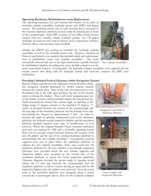
<strong>Rehabilitation</strong> <strong>of</strong> <strong>the</strong> <strong>Hollywood</strong> <strong>Boulevard</strong> (S.R. <strong>820</strong>) <strong>Bascule</strong> <strong>Bridge</strong>Operating Machinery: Refurbishment versus ReplacementThe operating machinery for each bascule leaf consists <strong>of</strong> two pairs <strong>of</strong>hydraulic cylinder assemblies, hydraulic power unit (HPU) and pipingsystem. The hydraulic power unit <strong>of</strong> each movable leaf is mounted to<strong>the</strong> concrete machinery platform located inside <strong>the</strong> bascule pier in front<strong>of</strong> <strong>the</strong> counterweight. Each HPU consists <strong>of</strong>: two 20hp electric motorsintegral with two variable volume hydraulic pumps, one 130 gallonhydraulic oil reservoir with built-in heaters, level, temperature switches,brea<strong>the</strong>r, filters, and one main valve manifoldInitially <strong>the</strong> FDOT was seeking to refurbish <strong>the</strong> hydraulic cylinderassemblies as well as <strong>the</strong> hydraulic power unit. However, Hardesty &Hanover performed a cost analysis that included initial and maintenancecost <strong>of</strong> refurbished versus new cylinder assemblies. The studysuccessfully showed that due to <strong>the</strong> high maintenance typically incurred New Cylinder Assembliesby refurbished cylinders, providing new more durable cylinders was <strong>the</strong>more economical solution. Consequently, <strong>the</strong> hydraulic cylinder assemblies were replaced and <strong>the</strong>electric motors that along with <strong>the</strong> hydraulic pumps and reservoirs compose <strong>the</strong> HPU wererefurbished.Providing Unlimited Vertical Clearance within Navigation Channel<strong>Bascule</strong> bridges typically provide unlimited vertical clearance within<strong>the</strong> navigation channel delineated by fender systems locatedbetween <strong>the</strong> bascule piers. Prior to <strong>the</strong> start <strong>of</strong> construction, it wasdetermined that in <strong>the</strong> fully open position, <strong>the</strong> tips <strong>of</strong> <strong>the</strong> basculeleaves overhung <strong>the</strong> fenders. Thus a tall vessel navigating near one<strong>of</strong> <strong>the</strong> fender systems could potentially impact <strong>the</strong> bascule leaf tip.Field measurements showed <strong>the</strong> current angle <strong>of</strong> opening <strong>of</strong> <strong>the</strong>bridge being 67 degrees instead <strong>of</strong> <strong>the</strong> intended 75 degrees, 17inches <strong>of</strong> clearance between <strong>the</strong> bottom <strong>of</strong> <strong>the</strong> counterweight and<strong>the</strong> top edge <strong>of</strong> <strong>the</strong> machinery platform and <strong>the</strong> bascule leaves tipsencroaching <strong>the</strong> channel by approximately 5 feet. In order toincrease <strong>the</strong> angle <strong>of</strong> opening, components such as <strong>the</strong> machineryplatform, <strong>the</strong> hydraulic system inspection ladders and <strong>the</strong> machineryplatform handrail required some type <strong>of</strong> modification or evenremoval. When <strong>the</strong> original Hopkins Frame mounted machinerygear train was replaced in 1988 with a hydraulic operating system<strong>the</strong>re was not enough vertical clearance between <strong>the</strong> bottom <strong>of</strong> <strong>the</strong>new lift girders and <strong>the</strong> top <strong>of</strong> <strong>the</strong> existing machinery platform toaccommodate <strong>the</strong> new cylinder assemblies. Consequently concretesupports were cast in place below <strong>the</strong> machinery platform tosupport <strong>the</strong> new cylinder assemblies, holes were cored into <strong>the</strong>machinery platform for <strong>the</strong> new cylinders to go through, inspectionplatforms were provided below <strong>the</strong> new cylinder supports andinspection ladders were mounted on <strong>the</strong> vertical face <strong>of</strong> <strong>the</strong>machinery platform to access <strong>the</strong> lower inspection platforms.Clearance diagrams revealed <strong>the</strong> greater angle <strong>of</strong> opening wouldreduce <strong>the</strong> 17 inch gap between <strong>the</strong> counterweight and <strong>the</strong>machinery platform to about 3 inches leaving no space left for <strong>the</strong>inspection ladders; thus, <strong>the</strong> ladders were removed. Next, <strong>the</strong> coredholes in <strong>the</strong> machinery platform were elongated about 6 inchestowards <strong>the</strong> counterweight side to allow for <strong>the</strong> hydraulic cylindersElongated Cored Hole inMachinery PlatformAccess Ladders andInspection PlatformsHardesty & Hanover, LLP 6 <strong>of</strong> 7 12 th Biennial Movable <strong>Bridge</strong> Symposium


