MP 1, SQE-NE, SPA-NE, SP-NE - SCL Water
MP 1, SQE-NE, SPA-NE, SP-NE - SCL Water
MP 1, SQE-NE, SPA-NE, SP-NE - SCL Water
- No tags were found...

Create successful ePaper yourself
Turn your PDF publications into a flip-book with our unique Google optimized e-Paper software.
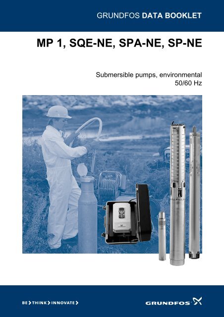
GRUNDFOS DATA BOOKLET<strong>MP</strong> 1, <strong>SQE</strong>-<strong>NE</strong>, <strong><strong>SP</strong>A</strong>-<strong>NE</strong>, <strong>SP</strong>-<strong>NE</strong>Submersible pumps, environmental50/60 Hz
ContentsGeneral dataPerformance range 3Environmental concern 4Product range and applications 5<strong>MP</strong> 1General data 6Technical data 8Material specification (pump) 9Material specification (motor) 9Accessories 11<strong>SQE</strong>-<strong>NE</strong>General data 13Features and benefits 15Examples of applications 18Communication 25Pump selection 30Curve conditions 32Technical data 38Material specification (pump) 39Material specification (motor) 39Material specification (cable) 39Accessories 41Order data 43<strong><strong>SP</strong>A</strong>-<strong>NE</strong>, <strong>SP</strong>-<strong>NE</strong>General data 44Features and benefits 47Curve conditions 49Technical data 58Material specification (pump) 58Material specification (motor) 58Accessories 59Central manangement system 65Head losses in ordinary water pipes 68Head losses in plastic pipes 69Order data 70Pumped liquidsResistance list 71Further product documentationWebCAPS 76WinCAPS 772
General data<strong>MP</strong> 1, <strong>SQE</strong>-<strong>NE</strong>, <strong><strong>SP</strong>A</strong>-<strong>NE</strong>, <strong>SP</strong>-<strong>NE</strong>Performance rangep[kPa]2000H[m]20050 Hz10001008008060060<strong><strong>SP</strong>A</strong>-<strong>NE</strong><strong>MP</strong> 1 <strong>SQE</strong> - <strong>NE</strong> <strong>SP</strong>-<strong>NE</strong>4004030020020100100.6 1 0.8 1 2 4 6 8 10 20 Q [m³/h]0.2 0.4 0.6 0.8 1 2 4 6 8Q [l/s]TM01 9132 0405Fig. 1 Performance range3
General data<strong>MP</strong> 1, <strong>SQE</strong>-<strong>NE</strong>, <strong><strong>SP</strong>A</strong>-<strong>NE</strong>, <strong>SP</strong>-<strong>NE</strong>Environmental concernConcern for the environment is growing.Waste disposal and treatment are being put into a legalframework.Investment in environmental protection is on theincrease and many sectors are taking concrete steps todevelop new solutions to environmental problems.To that end, Grundfos offers a complete product rangefor applications ranging from sampling to pumping ofpolluted drainage water.Sources of pollutionPollution of the groundwater and, thus, potentialcontamination of the drinking water resources can becaused by one or more of the following conditions:• leaking pipes, storage tanks and sewage systems• spills and leaks from tank lorries or wagons• floods, landslides, etc.In these cases, the potential damage to theenvironment can be minimised by pumping away thepollutants or the seepage water.Industrial wasteContinuous and safe production in modern industryrequires regulated disposal of waste. In the past,undesirable by products – such as residual materials orsubstances that could not be used, were often stored bycompanies on site. In the course of time, thesematerials and substances were often forgotten andsome of them seeped into the ground.Local authorities often have to deal with contaminatedsites when the companies responsible for thecontamination no longer exist or cannot afford theclean-up. Thanks to their high reliability and long life,Grundfos pumps offer a cost-effective solution.SamplingThe new Grundfos pump range featuring heads up to200 m and flow rates up to 22 m 3 /h are suitable forsampling of seepage water and groundwater. Inaddition to various geophysical methods, boreholescan be drilled to determine the chemical nature ofseepage water and groundwater in order to determinehow serious the contamination is.The Grundfos pumps are lowered into the borehole topump up water for sampling. After the sampling, thepumps are pulled up again, cleansed and lowered intothe next hole. Alternatively, the pumps are permanentlyinstalled in groundwater sampling wells for continuousduty.Industrial wastewater treatmentMany industries produce highly polluted effluent. Thelarge factories typically have their own treatmentplants, the size and capacity of which match the big cityplants.Today not only industrial process water but also coolingand surface water go through chemical and physicalpurification in separate systems before being led into awater treatment plant and then discharged or recycledinto production.Pumps are an important link between contaminatedand re-usable water. A number of environmentalprotection plants only exists thanks to the developmentof special environmental pumps, such as the costeffective,maintenance-free and highly reliableGrundfos <strong>MP</strong> 1, <strong>SQE</strong>-<strong>NE</strong>, <strong><strong>SP</strong>A</strong>-<strong>NE</strong> and <strong>SP</strong>-<strong>NE</strong> range,based on up-to-date material combinations.TM02 0249 0405Fig. 2 <strong>MP</strong> 1, <strong>SQE</strong>-<strong>NE</strong>, <strong><strong>SP</strong>A</strong>-<strong>NE</strong> and <strong>SP</strong>-<strong>NE</strong> pumps4
General data<strong>MP</strong> 1, <strong>SQE</strong>-<strong>NE</strong>, <strong><strong>SP</strong>A</strong>-<strong>NE</strong>, <strong>SP</strong>-<strong>NE</strong>Product range and applicationsTM01 9174 1300GR9407TM01 9175 1300Technical data <strong>MP</strong> 1 <strong>SQE</strong>-<strong>NE</strong> <strong><strong>SP</strong>A</strong>-<strong>NE</strong>, <strong>SP</strong>-<strong>NE</strong>Motor diameter 2" 3" 4"Nominal flow rate [m 3 /h] 0.1 - 1 2 and 5 3 - 17Max. head [m] 98 153 205Motor power [kW] 1.3 0.6 - 1.7 0.75 - 5.5Voltage supply [V] 1 x 220-240 V 1 x 200-240 V1 x 220-230/240 V3 x 200/220/380-415/500-525 VFrequency [Hz] 50/60 50/60 50Max. current [A] 5.5 11.2 13.0Max. liquid temperature [°C] 35 40 40ApplicationsSampling • • •Remedial pumping • •Withdrawal of contaminated/pollutedgroundwater (from dumps, chemical• •depots, etc.)Pumping in water treatment systems • • •Pumping of industrial process water • •<strong>Water</strong> quality monitoring • • •Mode of operationContinuous • •Intermittent • • •For further information about suitable pump types, see "Resistance list", page 73.5
General dataMonitor pump<strong>MP</strong> 1<strong>MP</strong> 1General dataThe <strong>MP</strong> 1 is an electrically driven 2" submersible pumpfor purging and sampling of contaminated/pollutedgroundwater.The pump is driven via an adjustable <strong>MP</strong> 1 converter inthe 50 to 400 Hz frequency range corresponding to apump speed of max. 23,000 min -1 and thus a nominalperformance of 1 m 3 /h at 75 m head.p[kPa]1000H[m]100400 Hz<strong>MP</strong> 1ISO 9906 Annex A90800807060060300 Hz504004030200 Hz2002010100 Hz000.0 0.4 0.8 1.2 1.6 2.0 2.4 Q [m³/h]0.0 0.2 0.4 0.6 Q [l/s]TM00 7778 2400Fig. 3 Performance range6
General dataMonitor pump<strong>MP</strong> 1ApplicationsThe <strong>MP</strong> 1 is designed for the pumping of contaminated/polluted groundwater for• purging• sampling• water quality monitoring.The <strong>MP</strong> 1 has been specially developed for sampling,i.e. pumping of small quantities of water to be sent tothe laboratory for analysis in order to establish• content of contaminants• concentration of contaminants• extension of contamination plume.The <strong>MP</strong> 1 pump is made of inert materials, which do notaffect the pumped liquid and thus the analysis results.The pump performance is adjusted by means of theconverter which controls the pump speed via thefrequency. In this way a steady, airfree water flow canbe achieved.The <strong>MP</strong> 1 offers efficient purging of the well beforesampling as a high pump performance is achievedwhen the frequency is raised. Maximum performance isat 400 Hz.However, the pump must not pump more water than thewell can yield. Otherwise, the water table may fall to alevel below the suction interconnector and air will besucked into the pump. Besides reducing the cooling ofthe motor, this situation may damage the pump. Inorder to avoid cleaning of the pump and possible crosscontamination,i.e. transfer of contaminants from onewell to another, dedicated installation of the pump isrecommended.This also saves valuable time for the samplingtechnician as he can quickly disconnect the converterand proceed to the next <strong>MP</strong> 1 installation. Thesubmersible drop cable is connected to the convertervia a plug connection so that disconnection is possiblewithout the use of tools.Fig. 4 <strong>MP</strong> 1 with converterType keyExample <strong>MP</strong> 1Monitor pumpRated flow[m 3 /h]Gr3101 - GrA60967
Technical dataMonitor pump<strong>MP</strong> 1Technical dataPumped liquidsContaminated/polluted groundwater, i.e. thin, nonexplosiveliquids without abrasive particles or fibres.Liquid temperature: 0 °C to +35 °C during operation.Maximum sand content: 50 g/m 3 .A larger sand content will reduce the life of service partsconsiderably.Note: The <strong>MP</strong> 1 pump is not built for the pumping ofconcentrated hydrocarbons, chemicals or explosiveliquids. As the pump has not been approved asexplosion-proof, local authorities and regulationsshould be consulted in case of doubt whether the <strong>MP</strong> 1pump may be used.If the density or the kinematic viscosity is higher thanthat of water, a higher input power than the nominalpower will be required, and the maximum number ofrevolutions must therefore be reduced.Overload protectionAs the motor and converter have overload protection,the maximum output at which the overload protectiondoes not switch off can be found through a trial-anderrorprocedure. Restart of the pump after switch-offrequires resetting of the converter on the start/stopswitch located on the front cover of the converter.Product rangeThe <strong>MP</strong> 1 is available in one size for connection to a <strong>MP</strong>1 converter and for Rp 3/4 pipe connection. The pumpcan be delivered from factory with or without motorliquid (demineralized water). The pump is fitted withvarious motor cable lengths, according to the tablebelow.Motor cable length[m]Product number <strong>MP</strong> 1incl. cable, connecting thread Rp 3/4Without motor liquid With motor liquid10 95065394 1A10510320 95065395 1A10520330 95065396 1A10530340 95065397 1A10540350 95065398 1A10550360 95065399 1A10560370 95065400 1A10570380 95065401 1A10580390 95065402 1A105903The <strong>MP</strong> 1 must be operated via a <strong>MP</strong> 1 converter whichis custom-built to Grundfos specifications.The converter is supplied without cable and plug formains connection.DesignationProduct number<strong>MP</strong> 1 converter 96765942<strong>MP</strong> 1 converter incl. cabinet 96765948<strong>MP</strong> 1 converter incl. 2 m cableand schuko plug96835207<strong>MP</strong> 1 converter incl. cabinet, 2 mcable and schuko plug968247218
Technical dataMonitor pump<strong>MP</strong> 1Material specification (pump)Pos. Components Materials DIN W.-Nr.201a Pump housing Stainless steel 1.4401232 Guide vane Stainless steel 1.4401230 Intermediate ring Stainless steel 1.4401285 Washer PTFE213 Impeller Stainless steel 1.4401207 Neck ring PTFE201a232230285213207215 Suction strainer Stainless steel 1.4401214 Suction interconnector Stainless steel 1.4401Material specification (motor)20215214222532Pos. Components Materials DIN W.-Nr.2RotorMagnetic PTFEcoatedsteel sheetsembedded withaluminium24322b224Shaft Stainless steel 1.4460Radial bearing, rotatingTungsten carbide2a2bThrust washerPTFE32 Seal ring FKM12,24,74a4,51O-ringsRadial bearings,stationaryFKMStainless steelCeramics1.4401StatorRotor can Stainless steel 1.4401Stator housing Stainless steel 1.4401P1:1300W U:3x220V Imax:5.5 400Hz n:22800RPMIP58 Tmax AMB:35 C90M Made in USA XXXXXXXX73,222Screws Stainless steel 1.44012074Motor cable (4 x 1 mm 2 ETFE/FEP)(Tefzel)Cable screws Stainless steel 1.4401WashersPTFE/brassCable seal bushes FK<strong>MP</strong>lug pinsGoldplated brassFilling screw(for motor liquid)Stainless steel 1.446047412a731274aTM00 0530 3100Fig. 5 <strong>MP</strong> 19
Technical dataMonitor pump<strong>MP</strong> 1<strong>MP</strong> 1Power consumption:Voltage:Current:Motor protection:<strong>Water</strong> temperature:Continuous operation:1.3 kW3 x 220 V, 400 HzMax. 5.5 APipe connection: Rp 3/4Net weight (pump only):<strong>MP</strong> 1 converterSupply voltage:Built-in thermal switch.0 °C to +35 °C.Maximum 500 hours.2.5 kg.1 x 220-240 V– 15 %/+ 10 %, 50/60 Hz, PEMinimum generator size: With voltage control: 2.5 kVA.4.0 kVA (recommended size).Rated current:Without voltage control:5.0 kVA.10 APower factor: 0.65Connecting cable: 3 x 1.5 mm 23 m with plugOutput voltage:Motor protection:Acceleration time:Deceleration time:Enclosure class: IP 65.Ambient temperatureduring operation:3 x 25 V, 50 Hz to3 x 210 V, 400 HzBuilt-in overcurrent protectivedevice, set to 6.1 A.0 to 400 Hz: Max. 6 sec.400 to 0 Hz: Max. 6 sec.–10 °C to 45 °C.Relative air humidity: Maximum 95 %.Net weight:7.7 kg.287Fig. 6 <strong>MP</strong> 1 dimensions45Rp 3/4TM00 0531 0894ServiceOnly pumps that can be certified as uncontaminated,i.e. pumps containing no hazardous and/or toxicmaterial, may be returned to Grundfos for servicing.To prevent injury to the health of persons involved andto the environment, a document certifying that thepump is clean is required.Grundfos must receive this certificate before theproduct. Otherwise Grundfos will refuse to accept theproduct for servicing. Possible costs of returning theproduct are paid by the customer.TM04 1456 1008 - TM04 1757 1008Fig. 7 Converter dimensions10
AccessoriesMonitor pump<strong>MP</strong> 1AccessoriesConverter cabinetDescriptionFacilitates handling of the converter and protects it against sprinkles andsplashes of water.Enclosure class: IP 65.Product number96765941TM04 1757 1008Straining wireDescription Length [m] Product numberIf a flexible hose is connected to the pump,the use of a straining wire is recommendedto prevent the pump from being droppedinto the well or the motor cable from beingdamaged in case the hose stretches.10 1A505120 1A505230 1A505340 1A5054The wire is supplied with 2 wire locks.50 1A5055TM00 0875 4092Diameter: 2.3 mm.Material:Stainless steel DIN W.-Nr. 1.4401,AISI 316.Separate wire lock.60 1A505670 1A505780 1A505890 1A5059ID5746Wire holder for straining wireDescription Connecting thread Product numberTM00 1277 4992The wire holder is fitted direct on top of thepump and fastened by means of the riserpipe or a hose union.Material:Stainless steel DIN W.-Nr. 1.4401,AISI 316.Rp 3/41A001811
AccessoriesMonitor pump<strong>MP</strong> 1Flexible hoseDescription Length [m] Product number10 1A008120 1A0082Diameter: 18/13 mm.30 1A008340 1A0084Material: PTFE transparent.50 1A0085Pressure: Max. 10 bar.60 1A008670 1A008780 1A008890 1A0089Coupling for flexible hoseDescription Connecting thread Product numberThe flexible hose is available with Rp 3/4compression coupling fitting.TM00 1278 4992Material:Stainless steel DIN W.-Nr. 1.4401,AISI 316.Rp 3/41A5030Flow sleeveDescriptionProduct numberIf the internal borehole diameter exceeds 80 mm, the pump can be fitted with aflow sleeve to ensure cooling of the motor.TM00 1286 4992External diameter: 55 mm.Total length: 310 mm.Material:Stainless steel DIN W.-Nr. 1.4401, AISI 316.1A10840512
General dataSubmersible pumps<strong>SQE</strong>-<strong>NE</strong><strong>SQE</strong>-<strong>NE</strong>General datap[kPa]2000H[m]200<strong>SQE</strong> - <strong>NE</strong>ISO 9906 Annex A1000900800700100806006050040040300<strong>SQE</strong> 2-<strong>NE</strong><strong>SQE</strong> 5-<strong>NE</strong>20020100100 1 2 3 4 5 6 7 8 Q [m³/h]0.0 0.5 1.0 1.5 2.0 Q [l/s]TM01 9343 3704Fig. 8 Performance range13
General dataSubmersible pumps<strong>SQE</strong>-<strong>NE</strong>Applications<strong>SQE</strong>-<strong>NE</strong> pumps are suitable for the followingapplications• sampling• remedial pumping• withdrawal of contaminated water at– dumps– chemical depots– industrial sites– garages and filling stations• pumping in water treatment systems• pumping of industrial process water• water quality monitoring.<strong>SQE</strong>-<strong>NE</strong> pumps are built for both continuous andintermittent operation.Note: For other applications, please contact Grundfos.Pump and motor<strong>SQE</strong>-<strong>NE</strong> pumps offer the following features:• dry-running protection• high efficiency of pump and motor• wear resistance• protection against upthrust• soft starting• overvoltage and undervoltage protection• overload protection• overtemperature protection• variable speed• electronic control and communication.The submersible <strong>SQE</strong>-<strong>NE</strong> pump is fitted with a singlephaseGrundfos MSE 3-<strong>NE</strong> motor, which is available inthree sizes with a maximum power P 2 of 1.7 kW.The MSE 3-<strong>NE</strong> permanent magnet motors are based onstate-of-the-art technology, which is the main reasonfor their high efficiency. The integrated electronic unit ofthe motors comprises a frequency converter for softstarting.The <strong>SQE</strong>-<strong>NE</strong> pump features variable speed which isoffered through frequency control. Consequently thepump can be set to operate in any duty point in therange between the min. and max. pump performancecurves.The <strong>SQE</strong>-<strong>NE</strong> pump features communication with theGrundfos CU 300 control unit, which can be operatedwith the Grundfos R100 remote control.The <strong>SQE</strong>-<strong>NE</strong> pump can also operate without theCU 300.The CU 300 provides full control of the <strong>SQE</strong>-<strong>NE</strong> pump.In case of a pump fault, an alarm will be indicated on thefront of the CU 300.The R100 enables monitoring of the installation andchanging of the factory settings.Pump and motor rangeProduct Description Material<strong>SQE</strong>-<strong>NE</strong> pump 2 and 5 m 3 /hMSE 3-<strong>NE</strong> motorPipe connectionType keyPumped liquidsThe <strong>SQE</strong>-<strong>NE</strong> pump is suitable for use with slightlyaggressive liquids such as contaminated groundwaterand groundwater containing hydrogen carbonate.<strong>SQE</strong>-<strong>NE</strong> pumps can pump liquids with a sand contentof up to 50 g/m 3 . A higher content of sand will reducethe pump life.Operating rangeFlow: 0.3 to 7.5 m 3 /hHead: Max. 153 m.Single-phasemax. 1.7 kWStainless steelDIN 1.4401, AISI 316Stainless steelDIN 1.4401, AISI 316Pump typeThreaded connection<strong>SQE</strong> 2-<strong>NE</strong> Rp 1 1/4<strong>SQE</strong> 5-<strong>NE</strong> Rp 1 1/2Example SQ E 2 -50 <strong>NE</strong>Pump rangeE = Electronic control and communicationRated flow [in m 3 /h]Head at rated flow [in mm]Material code:N = Stainless steel DIN W.-Nr. 1.4401E = Environmental.The pump is suitable for pumping of polluted liquids14
Features and benefitsSubmersible pumps<strong>SQE</strong>-<strong>NE</strong>Features and benefitsDry-running protectionThe <strong>SQE</strong>-<strong>NE</strong> pumps are protected against dry running.A factory-set P cut-out value ensures cut-out of the pumpin case of lack of water in the borehole thus preventinga burnout of the motor.High pump efficiencyThe hydraulic pump components are PVDF CN-Freinforced with 10 % carbon fibre. The hydraulic designgives high pump efficiency meaning low energyconsumption and therefore low energy costs.High motor efficiencyThe MSE 3-<strong>NE</strong> motor is based on a permanent-magnetrotor (PM motor) featuring high efficiency within a wideload range.The high, flat efficiency curve of the PM motor enablesthe same motor to cover a wide power range comparedto conventional AC motors. For <strong>SQE</strong>-<strong>NE</strong> pumps, thismeans fewer motor variants.Wear resistanceThe <strong>SQE</strong>-<strong>NE</strong> pump design features impellers which arenot fastened to the shaft ("floating"). Each impeller hasits own tungsten-carbide/ceramic bearing. The designand materials chosen ensure high wear resistance tosand for long product life.Protection against upthrustStarting up a pump with a very low counter-pressureinvolves the risk of the entire impeller stack being lifted– also called upthrust. Upthrust may cause breakdownof both pump and motor. The MSE 3-<strong>NE</strong> is fitted with atop bearing protecting both pump and motor againstupthrust and thus preventing breakdown during thecritical start-up phase.Eta[%]706560555045HPFig. 9 Dry-running protectionFig. 10 Motor efficiencyP1P cut-out200 250 300 350 400 450 500 550 P2 [W]Fig. 11 Pump parts including bearingsQQMSE MS 3-<strong>NE</strong> 3Conventional 3 3 ph.Conventional 1 1 ph. phTM01 2751 2298TM01 2698 2298TM01 3141 349815
Features and benefitsSubmersible pumps<strong>SQE</strong>-<strong>NE</strong>Excellent starting capabilitiesThe integrated electronic unit of the MSE 3-<strong>NE</strong> motorsfeatures soft starting. Soft start reduces the startingcurrent and thus gives the pump a smooth and steadyacceleration.AmpsDOL (direct on line)The soft starter minimises the risk of pump wear andprevents overloading of the mains during start-up.The excellent starting capabilities are a result of thehigh locked-rotor torque of the permanent-magnetmotor together with the few pump stages. The highstarting reliability also applies in case of low voltagesupply.Soft startFig. 12 DOL versus soft startingsec.TM01 3479 4198Overvoltage and undervoltage protectionOvervoltage and undervoltage may occur in case ofunstable voltage supply.The integrated protection of the MSE 3-<strong>NE</strong> motorsprotects the motor in case the voltage falls outside thepermissible voltage range.The pump will be cut out if the voltage falls below 150V or rises above 315 V. The motor is automatically cutin again when the voltage is again within thepermissible voltage range. Therefore, no extraprotection relay is needed.Overload protectionExposure of the pump to heavy load causes the currentconsumption to rise. The motor will automaticallycompensate for this by reducing the speed to 3000 rpm.Further overload will lead to stop.The same applies if the rotor is being prevented fromrotating. This will automatically be detected and thepower supply cut out. Consequently, no extra motorprotection is required.Overtemperature protectionA permanent-magnet motor gives off very little heat toits surroundings. In combination with an efficientinternal circulation system providing cooling of therotor, stator and bearings, this ensures optimumoperating conditions for the motor.As extra protection, the electronic unit has a built-intemperature sensor. When the temperature rises toohigh, the motor is cut out. When the temperature hasdropped, the motor is automatically cut in again.ReliabilityDesigned with a view to high reliability, the MSE 3-<strong>NE</strong>motors offer the following features• tungsten-carbide/ceramic bearings• thrust bearings protecting against downthrust• product life time equal to conventional AC motors.16
Features and benefitsSubmersible pumps<strong>SQE</strong>-<strong>NE</strong>Variable speedThe MSE 3-<strong>NE</strong> motor enables continuously variablespeed control between the 3000 and 10700 rpm. Thepump can be set to operate in any duty point in therange between the 3000 and 10700 rpm performancecurves of the pump. Consequently, the pumpperformance can be adapted to any specificrequirement.The variable-speed control facility requires the use ofthe CU 300 or CU 301 control unit and the R100 remotecontrol.For the calculation of pump speed, the PC tool "<strong>SQE</strong>speed calculation" is available on CD-ROM as anaccessory, see page 42. On the basis of a requiredhead and flow, the speed of the motor is calculated.Furthermore, the specific pump performance curve canbe illustrated.AllowedFig. 13 Installation of <strong>SQE</strong>-<strong>NE</strong> pumpsNot allowedTM01 1375 1498InstallationThe <strong>SQE</strong>-<strong>NE</strong> is suitable for vertical and horizontalinstallation or any position inbetween.Note: The pump must never be installed below thehorizontal plane in relation to the motor.The following features ensure simple installation of the<strong>SQE</strong>-<strong>NE</strong> pumps:• Built-in non-return valve with spring.• Low weight for user-friendly handling.• Installation in 3" or larger boreholes.• Only an on/off switch is required, meaning that thereis no need for motor starter or starter box.• A cable with plug is available on request(up to 80 m).For horizontal installation a flow sleeve isrecommended• to ensure sufficient flow velocity past the motor andthus provide sufficient cooling and• to prevent the motor and electronic unit from beingburied in sand or mud.ServiceThe modular pump and motor design facilitatesinstallation and service. The cable with plug is fitted tothe pump with screws, which facilitates replacement.Only pumps that can be certified as uncontaminated,i.e. pumps containing no hazardous and/or toxicmaterial, may be returned to Grundfos for servicing.To prevent injury to the health of persons involved andto the environment, a document certifying that thepump is clean is required.Grundfos must receive this certificate before theproduct. Otherwise Grundfos will refuse to accept theproduct for servicing. Possible costs of returning theproduct are paid by the customer.17
Examples of applicationsSubmersible pumps<strong>SQE</strong>-<strong>NE</strong>Examples of applicationsSampling at variable speedFunction and benefitsThe <strong>SQE</strong>-<strong>NE</strong> pump is ideally suited for the sampling ofwater as the pump materials are resistant to aqueoussolutions of chemicals, oils, etc.Prior to sampling, the well must be purged severaltimes at high pump speed to make sure that the sampleis representative. Subsequently the sample must betaken at low pump speed in order not to affect thequality of the water and to avoid degassing.215321 <strong>SQE</strong>-<strong>NE</strong> pump2 Cable3 Cable clips5 CU 300 control unit21 Mains connection, 1 x 200-240 V, 50/60 Hz22 Riser pipe30 Straining wire31 Wire clamp, 2 per lifting eye32 <strong>SP</strong>P 1 potentiometer22Recommendedmin. 0.5 m2330311min. 0.5 mTM01 9028 1000Fig. 14 Sampling at variable speedSampling at variable speedPos. Part Type No. of units Product number Unit price Total price1 Pump <strong>SQE</strong>-<strong>NE</strong>2 Cable3 Cable clips5 Control unit CU 30022 Riser pipe30 Straining wire31 Wire clamp 2 per lifting eye32 Potentiometer <strong>SP</strong>P 118
Examples of applicationsSubmersible pumps<strong>SQE</strong>-<strong>NE</strong>Dewatering systemFunction and benefitsThe dewatering system is ideal in applications wherethe pump often runs dry, e.g. in boreholes with a lowyield or in boreholes where the water table should belowered, e.g. in a building site.Air entering the pump together with water due to a dropin the water level causes the motor load and,consequently, the pump power input to decrease.If the pump power input falls below a minimum powerlimit set via the R100, the pump stops.The pump setting can be made in a workshop by meansof a CU 300, and subsequently the pump can beinstalled in the borehole. If the setting is made in thisway, it is not necessary to include the CU 300 in theapplication below.215R10029Stop timeRun time1 <strong>SQE</strong>-<strong>NE</strong> pump2 Cable3 Cable clips5 CU 300 control unit21 Mains connection, 1 x 200-240 V, 50/60 Hz22 Riser pipe29 R100 remote control30 Straining wire31 Wire clamp31222330311TM01 9412 1900Fig. 15 Dewatering systemDewatering systemPos. Part Type No. of units Product number Unit price Total price1 Pump <strong>SQE</strong>-<strong>NE</strong>2 Cable3 Cable clips5 Control unit CU 30022 Riser pipe29 Remote control R10030 Straining wire31 Wire clamp19
Examples of applicationsSubmersible pumps<strong>SQE</strong>-<strong>NE</strong>Maintaining a constant water tableFunctioning and benefitsThe water table can be maintained at a constant levelby adjusting the pump performance. For example,maintaining a constant water table is useful when thegroundwater should be kept out of a building site orwhen salt water should be kept from penetrating aborehole containing potable water.The example shows how to maintain a constant watertable by adjusting the pump performance. At low or noflow and thereby low performance, the flowmeterensures that the pump stops in order to avoidoverheating of the motor.SensorsLevel Description ReactionLevel sensor (pos. 11)Warning (max.)Desired levelWarning (min.)Too high water level.Possible cause:Insufficient pump capacity.The water level that shouldbe maintained.Too low water level.Possible cause:Too high pump capacity.Alarm relayoperates.Alarm relayoperates.5R10021 291 <strong>SQE</strong>-<strong>NE</strong> pump2 Cable3 Cable clips5 CU 300 control unit11 Level sensor21 Mains connection, 1 x 200-240 V, 50/60 Hz22 Riser pipe29 R100 remote control30 Straining wire31 Wire clamp3122233031111Warning (max.).Desired levelWarning (min.).Recommendedmin. 0.5 m.min. 0.5 mTM01 2459 4801Fig. 16 Maintaining a constant water tableMaintaining a constant water tablePos. Part Type No. of units Product number Unit price Total price1 Pump <strong>SQE</strong>-<strong>NE</strong>2 Cable3 Cable clips5 Control unit CU 30011 Level sensor22 Riser pipe29 Remote control R10030 Straining wire31 Wire clamp20
Examples of applicationsSubmersible pumps<strong>SQE</strong>-<strong>NE</strong>Systems with three sensors connectedFunction and benefitsThe CU 300 enables systems with three sensorsconnected.SensorsLevel Description ReactionpH sensor on ground (pos. 33)WarningAlarmThe pH value is close to themaximum value allowed.The pH value has reachedthe maximum value allowed.Alarm relayoperates.The pump isstopped.The indicator light"sensor alarm" is on.Level Description ReactionLevel sensor in borehole (pos. 11)Warning (top)Max. (start)Min. (stop)Warning(bottom)Too high water level.Possible cause:Insufficient pump capacity.When the water has reachedthis level, the pump starts.When the water has reachedthis level, the pump stops.Too low water level inborehole.Possible cause:Pumping in adjacentboreholes.Alarm relayoperates.Green indicator lightin on/off button isconstantly on.Green indicator lightin on/off buttonflashes.Alarm relayoperates.5R10021 29pH 100 %AlarmWarning09Alarm33311 <strong>SQE</strong>-<strong>NE</strong> pump2 Cable3 Cable clips5 CU 300 control unit9 Pulse flowmeter11 Level sensor21 Mains connection, 1 x 200-240 V, 50/60 Hz22 Riser pipe29 R100 remote control30 Straining wire31 Wire clamp33 pH sensor22233031111WarningMax. (start)Min. (stop)Recommendedmin. 0.5 mmin. 0.5 mTM01 9394 1800Fig. 17 Systems with three sensors connectedSystems with three sensors connectedPos. Part Type No. of units Product number Unit price Total price1 Pump <strong>SQE</strong>-<strong>NE</strong>2 Cable3 Cable clips5 Control unit CU 3009 Pulse flowmeter11 Level sensor22 Riser pipe29 Remote control R10030 Straining wire31 Wire clamp33 pH sensor21
Examples of applicationsSubmersible pumps<strong>SQE</strong>-<strong>NE</strong>Filling a tank from borehole using level controlFunction and benefitsThe <strong>SQE</strong>-<strong>NE</strong> pump with CU 300 is ideal for filling a tankfrom a borehole.SensorsLevel Description ReactionLevel sensor in tank (pos. 11)Warning (top)Max. (stop)Min. (start)Warning(bottom)Too high water level, e.g. dueto rainwater in tank.When the water has reachedthis level, the pump stops.When the water has reachedthis level, the pump stops.Too low water level, e.g. dueto a too small pumpperformance.Level sensor in borehole (pos. 12)AlarmToo low water level, e.g. dueto a too small pumpperformance.Alarm relayoperates.Green indicator lightin on/off buttonflashes.Green indicator lightin on/off button isconstantly on.Alarm relayoperates.The pump stops.Alarm relayoperates, and theindicator light"sensor alarm” is on.521WarningMax. (stop)Min. (start)Warning11R1002922311 <strong>SQE</strong>-<strong>NE</strong> pump2 Cable3 Cable clips5 CU 300 control unit11,12 Level sensor21 Mains connection, 1 x 200-240 V, 50/60 Hz22 Riser pipe29 R100 remote control30 Straining wire31 Wire clamp22233031121AlarmRecommendedmin. 0.5 mmin. 0.5 mTM01 9395 1800Fig. 18 Filling a tank form borehole using level controlFilling a tank from borehole using level controlPos. Part Type No. of units Product number Unit price Total price1 Pump <strong>SQE</strong>-<strong>NE</strong>2 Cable3 Cable clips5 Control unit CU 30011 Level sensor12 Level sensor22 Riser pipe29 Remote control R10030 Straining wire31 Wire clamp22
Examples of applicationsSubmersible pumps<strong>SQE</strong>-<strong>NE</strong>Remedial pumping with water quality monitoringFunction and benefitsBy means of sensor communication, it is possible tocarry out remedial pumping of liquids such as watersolublechemicals, oils, etc.Remedial pumping is carried out, for example, inconnection with the treatment of the groundwatersurrounding a dump. The process can involve bothrecovery and treatment by separating the chemicals oroil from the recovered water. Subsequently the water isled back into the ground.SensorsLevel Description ReactionLevel sensor in borehole (pos. 11)Warning (top)Max. (start)Min. (stop)Warning(bottom)Too high water level inborehole.Possible cause:Insufficient pump capacity.When the water reaches thislevel, the pump starts.When the water reaches thislevel, the pump stops.Too low water level in borehole.Possible cause:Pumping in adjacent boreholes.pH sensor on ground (pos. 33)WarningAlarmThe pH value is close to themaximum value allowed.The pH value has reached themaximum value allowed.Alarm relayoperates.Green indicator lightin on/off button isconstantly on.Green indicator lightin on/off buttonflashes.Alarm relayoperates.Alarm relayoperates.The pump stops.The indicator light“sensor alarm” is on.5R10021 29pH 100 %33AlarmWarning1 <strong>SQE</strong>-<strong>NE</strong> pump2 Cable3 Cable clips5 CU 300 control unit11 Level sensor21 Mains connection, 1 x 200-240 V, 50/60 Hz22 Riser pipe29 R100 remote control30 Straining wire31 Wire clamp33 pH sensor3122233031111WarningMax. (start)Min. (stop)WarningRecommendedmin. 0.5 mmin. 0.5 mTM01 9397 1800Fig. 19 Remedial pumping with water quality monitoringRemedial pumping with water quality monitoringPos. Part Type No. of units Product number Unit price Total price1 Pump <strong>SQE</strong>-<strong>NE</strong>2 Cable3 Cable clips5 Control unit CU 30011 Level sensor22 Riser pipe29 Remote control R10030 Straining wire31 Wire clamp33 pH sensor23
Examples of applicationsSubmersible pumps<strong>SQE</strong>-<strong>NE</strong>Workshop setting of operating parametersUsing the R100 and the CU 300 enables change of themotor speed in a workshop and thereby setting of thepump to a specific performance.A program called "<strong>SQE</strong> Speed Calculation" has beendeveloped for the calculation of the speed in order toobtain the required flow rate and head.Dry-running protectionThe P cut-out value , ensuring dry-running protection isfactory-set for the <strong>SQE</strong>-<strong>NE</strong> pump.If the speed of the <strong>SQE</strong>-<strong>NE</strong> pump is reduced by morethan 1000 min -1 , the P cut-out value must be readjustedby means of the CU 300 and R100.CU 300R100Note: The <strong>SQE</strong>-<strong>NE</strong> pump must not be started until the pump hasbeen completely submerged below the water table.However, the change of the motor speed can be made even if thepump is not running.<strong>SQE</strong>-<strong>NE</strong>TM01 8650 4801Fig. 20 Workshop setting of operating parameteresWorkshop setting of operating parametersPart Type No. of units Product number Unit price Total pricePump<strong>SQE</strong>-<strong>NE</strong>,Remote controlR100Control unit CU 300“<strong>SQE</strong> Speed Calculation”24
Examples of applicationsSubmersible pumps<strong>SQE</strong>-<strong>NE</strong>CommunicationCU 300 control unitThe CU 300 is a control and communication unitspecially developed for the <strong>SQE</strong>-<strong>NE</strong> submersiblepumps.LEDalarmindicationOn/Off buttonwith red andgreen indicatorlightsThe CU 300 control unit provides• easy adjustment to a specific borehole• full control of the <strong>SQE</strong>-<strong>NE</strong> pumps• two-way communication with the <strong>SQE</strong>-<strong>NE</strong> pumps• alarm indication of pump operation by diodes on thefront• the possibility of starting, stopping and resetting thepump simply by means of a push-button.The CU 300 communicates with the pump via the powersupply cable. This is called mains-borne signalling orpower line communication. Using this concept meansthat no extra cables between the CU 300 and the pumpare required.The following alarms can be indicated by the CU 300:• No contact• Overvoltage• Undervoltage• Dry running• Speed reduction• Overtemperature• Overload• Sensor alarm.The CU 300 incorporates• external signal input for two analog sensors and onedigital sensor• relay output for external alarm indication• control according to the signals received, e.g.concerning flow, pressure, water level andconductivity.Furthermore, the CU 300 offers the possibility of remotecontrol.Fig. 21 CU 300 frontPower supply entrySubmersible dropcable entry195Fig. 22 CU 300 cable entriesFig. 23 CU 300 dimensionsDimensions stated in mm.IR communicationExtra cable entriesFieldbus entrySensor entry232 114TM01 2760 4801TM01 2761 4801TM01 2781 4601R100 remote controlWireless infrared remote control of the CU 300 ispossible with the R100.With the R100 it is possible to monitor and change theoperating parameters, see the R100 menu overview onpage 26. The R100 is a strong tool in case fault findingis required.25
CommunicationSubmersible pumps<strong>SQE</strong>-<strong>NE</strong>R100 menu overview for the CU 300SetStartLight0. General 1. OperationContrast2. Status 3. Limits 4. Installation1.12.13.14.11.22.23.24.21.32.33.34.31.42.43.44.41.52.53.54.51.62.63.64.61.72.73.74.71.82.83.84.82.93.94.93.104.10Note: This menu is an example, not the factory-setting.3.113.12TM01 2675 0201Fig. 24 Menu overview26
CommunicationSubmersible pumps<strong>SQE</strong>-<strong>NE</strong>R100 menus for CU 3000. General1. Operation1.1 Setpoint setting1.2 Selection of operating mode1.3 Alarm indication.2. StatusThe indication of:2.1 Actual operating mode2.2 Actual and external setpoint2.3 Actual motor temperature2.4 Actual motor speed2.5 Actual power input and accumulated motor powerconsumption2.6 Accumulated number of operating hours andaccumulated number of starts2.7 Actual values of sensors 1 and 2, respectively2.8 Actual values of the digital input2.9 Accumulated flow and the power used to pump1m 3 .The R100 offers the possibility of making a number ofsettings:4. Installation4.1 Selection of controller4.2 Setting of external setpoint4.3 Setting of automatic restart time4.4 Allocation of individual start delays4.5 Setting of the stop and run times for thedewatering function4.6 Setting of the dry-running stop limit4.7 Activation or deactivation of the dry-runningprotection4.8 Setting of the maximum motor speed4.9 Activation or deactivation of the On/Off button onthe CU 3004.10 Allocation of number where more than one CU 300are installed.3. LimitsThe setting of:3.1 Sensor 1 parameters3.2 Min. and max. stop limits of sensor 13.3 Min. and max. warning limits of sensor 13.4 Min. and max. alarm limits of sensor 13.5 Sensor 2 parameters3.6 Min. and max. stop limits of sensor 23.7 Min. and max. warning limits of sensor 23.8 Min. and max. alarm limits of sensor 23.9 Filling or emptying3.10 Setting of the function of the digital sensorconnected to the digital input3.11 Setting of the water quantity stop limit and settingof the sensor to detect water quantity3.12 Setting of the temperature warning limits of themotor electronics.27
CommunicationSubmersible pumps<strong>SQE</strong>-<strong>NE</strong>Examples of R100 displaysMenu OPERATIONAccumulated number of operating hours and numberof startsSetpoint setting1.1The pump is factory set to maximum speed,10,700 min -1 . The R100 makes it possible to reduce thepump speed by changing the setpoint. The speed canbe set to 3,000 - 10,700 min -1 , at intervals of 100 min -1 .The unit of the setpoint is automatically changedaccording to the unit of the sensor connected to sensorinput 1.Example: Sensor input 1 is connected to a pressuresensor using the unit metre (m) and the range 0-60.Consequently, the setpoint of display 1.1 can be setwithin the range between 0-60 m.Menu STATUSThe displays appearing in this menu are status displaysonly. It is not possible to change settings in this menu.Accumulated flow2.9Display 2.9 shows the water quantity (in m 3 ) pumped.The value shown is the accumulated flow registered bythe sensor selected in display 3.11.The power used to pump 1 m 3 is shown in the displayas energy per m 3 (kWh/m 3 ).It is possible to read the status of the accumulated flowand energy per m 3 at any time.2.6The value of operating hours and the number of startsare values accumulated from the time of installation,and they cannot be reset.Both values are stored in the motor electronics, andthey are kept even if the CU 300 is replaced.The number of operating hours is registered every twominutes of continuous operation.Menu LIMITSSensor 13.1The setting of sensor 1.Depending on the type of sensor, the following settingscan be made:• Sensor output:– (not active), 0-10 V, 2-10 V, 0-20 mA, 4-20 mA.• Setting range unit:m 3 /h, m, %, GPM, ft.• Sensor minimum value: 0-249 (0, 1, 2, 3.....249).• Sensor maximum value: 1-250 (1, 2, 3, 4.....250).28
CommunicationSubmersible pumps<strong>SQE</strong>-<strong>NE</strong>Alarm indicationThe CU 300 offers the following alarm indications.Alarm Description The pump will be restarted automaticallyNo contactNo contact/communication between the CU 300 and the<strong>SQE</strong>-<strong>NE</strong> pump.–Note: This alarm does not affect pump operation.Overvoltage The supply voltage exceeds the limit value. when the voltage is within the specified range.Undervoltage The supply voltage is below the limit value. when the voltage is within the specified range.Dry runningBenefits of CU 300/R100The dry-running protection of the pump has been activated.after 5 minutes (default), or a period set with theR100.Speed reductionThe motor speed is reduced.Note: The speed is resumed when the cause has been –remedied or has disappeared.Overtemperature The motor temperature exceeds the limit value. when the motor electronics has cooled sufficiently.Overloadafter 5 minutes (default), or a period set with theThe current consumption of the motor exceeds the value set.R100.Sensor alarmSensor alarm may be caused by the following:The measured value has dropped outside the measuringrange set.The sensor is defective.The sensor output setting made via the R100 is incorrect.after 5 minutes (default), or a period with the R100.Alarm Description The following items are no longer requiredNo contactProvides knowledge of contact between the <strong>SQE</strong>-<strong>NE</strong> pumpand the CU 300.–Overvoltage The supply voltage is measured. Overvoltage relay.Undervoltage The supply voltage is measured. Undervoltage relay.Dry running Provides dry-running protection of the pump. Level relay, electrodes, cables.Speed reductionEnsures pump operation at a moderate undervoltage andoverload, thereby ensuring that the motor is not overloaded.Urgent need for service.The pump is stopped at a critical temperature. Once theOvertemperaturemotor electronics has cooled sufficiently, the motor will restart –automatically.Overload Provides overload protection of the motor. Motor starter.Sensor alarmSensors can be connected directly to the CU 300.The sensor signals are monitored.External control unit.29
CommunicationSubmersible pumps<strong>SQE</strong>-<strong>NE</strong>Pump selectionDetermining head and flowPump selection should be based on the required flowand head.1. FlowSelection of the most suitable pump size should bebased on the likely maximum flow of liquid expected tobe pumped.2. HeadH [m] = p outlet x 10.2 + H geo + H fp outlet = Required pressure at the outletH geo =H f =Difference in height between the lowest water leveland the pump outletFriction loss in pipes and tubes.See table below.Calculation exampleRequired flow: 3.8 m 3 /hp outlet = 3 barH geo = 25 mThe plastic pipes have a diameter of ∅32 and a lengthof 25 m.This will give:H f = Value from table/100 x length of pipeH f = 18/100 x 25 m = 4.5 mH [m] = p outlet x 10.2 + H geo + H f= 3 x 10.2 + 25 m + 4.5 m = 60.1 mSelected at Q = 3.8 m 3 /h, H = 60.1 mFor selection of the optimum pump type, see the nextpage.Examples of head losses in plastic pipes and ordinary water pipes: H fNote: The material of the riser pipe must be selectedaccording to the pumped liquid.Upper figures indicate the water velocity in m/sec.Lower figures indicate head loss in metres per100 metres of straight pipes.Volume of water Plastic pipes* (PELM/PEH PN 10 PELM) Ordinary water pipes**m 3 /h Litres/min. Litres/sec.0.6 10 0.160.9 15 0.251.2 20 0.331.5 25 0.421.8 30 0.502.1 35 0.582.4 40 0.673.0 50 0.833.6 60 1.004.2 70 1.124.8 80 1.335.4 90 1.506.0 100 1.677.5 125 2.089.0 150 2.5010.5 175 2.92* The table is based on a monogram.Roughness: K = 0.01 mm.<strong>Water</strong> temperature: t = 10 °C.2520.40.491.80.764.01.06.41.310.01.5313.01.7716.02.0522.02.5437.03.0643.03.4350.0Nominal pipe diameter in inches and internal diameter in [mm]3226.20.300.660.461.140.612.20.783.50.934.61.086.01.247.51.5411.01.8515.02.0818.02.4725.02.7830.03.139.03.8650.090 ° bends, slide valves 1.0 1.0 1.1 1.2 1.3T-pieces, non-return valves 4.0 4.0 4.0 5.0 5.04032.60.190.270.30.60.390.90.51.40.61.90.692.00.803.30.994.81.26.51.348.01.5910.51.812.02.016.02.4924.03.0033.03.538.05040.80.120.0850.190.180.250.280.320.430.380.570.440.700.510.930.631.400.761.900.862.501.023.001.153.501.284.61.596.61.918.62.2311.01/2"15.750.8559.9101.28220.111.71033.532.13849.932.56569.342.99391.543/4"21.250.4702.4070.7054.8620.9408.0351.17411.911.40916.501.64421.751.87927.662.34941.402.81957.743.28876.491"27.000.2920.7840.4381.5700.5842.5880.7303.8340.8765.2771.0226.9491.1688.8201.46013.141.75118.282.04324.182.33530.872.62738.302.91946.493.64970.411 1/4"35.750.2490.4160.3310.6770.4151.0040.4981.3790.5811.8110.6642.2900.8303.4030.9964.7181.1626.2311.3287.9401.4949.8281.66011.902.07517.932.49025.112.90433.321 1/2"41.250.2490.3460.3120.5100.3740.7000.4360.9140.4991.1600.6231.7190.7482.3750.8733.1320.9973.9881.1224.9271.2475.9721.5588.9671.87012.532.18216.66** The data are calculated in accordance with H. Lang’s new formula, a =0.02 and on the basis of a water temperature of 10 °C. The head lossin bends, slide valves, T-pieces and non-return valves is equivalent tothe metres of straight pipes stated in the last two lines of the table.30
Pump selectionSubmersible pumps<strong>SQE</strong>-<strong>NE</strong>Pump sizingImportant: The dry-running protection is effective onlywithin the recommended pump duty range, i.e. the boldcurves, see the performance curves.Pump typeDiameter of <strong>SQE</strong>-<strong>NE</strong> pumps: 74 mmExample:Power[kW]0.5/0.141.0/0.281.5/0.422.0/0.56Flow rate Q [m 3 /h] / [l/s]2.5/0.703.0/0.833.5/0.974.0/1.115.0/1.396.0/ 7.0/1.67 1.958.0/2.229.0/2.50Max. head [m](Q = 0 m 3 /h)RatedcurrentI 1/1 [A]PipeconnectionRpHead [m]230 V 200 V<strong>SQE</strong> 2-35 <strong>NE</strong> 0.4 39 37 35 31 26 19 - - - - - - - 41 3.0 3.5 1 1/4 747<strong>SQE</strong> 2-50 <strong>NE</strong> 0.6 58 56 52 47 38 26 - - - - - - - 59 4.1 5.0 1 1/4 747<strong>SQE</strong> 2-65 <strong>NE</strong> 0.8 76 73 68 60 49 34 - - - - - - - 78 5.3 6.2 1 1/4 774<strong>SQE</strong> 2-75 <strong>NE</strong> 1.0 94 89 83 74 60 42 - - - - - - - 97 6.5 7.5 1 1/4 828<strong>SQE</strong> 2-90 <strong>NE</strong> 1.2 111 106 98 87 71 50 - - - - - - - 116 7.6 9.1 1 1/4 864<strong>SQE</strong> 2-105 <strong>NE</strong> 1.4 129 123 113 100 82 58 - - - - - - - 135 8.7 10.4 1 1/4 891<strong>SQE</strong> 2-115 <strong>NE</strong> 1.6 147 139 128 114 94 66 - - - - - - - 153 9.9 11.8 1 1/4 945<strong>SQE</strong> 5-15 <strong>NE</strong> 0.27 - - - - - 14 13 13 11 8 - - - 16 2.3 2.7 1 1/2 747<strong>SQE</strong> 5-25 <strong>NE</strong> 0.54 - - - - - 28 27 25 22 17 - - - 31 3.8 4.6 1 1/2 747<strong>SQE</strong> 5-35 <strong>NE</strong> 0.81 - - - - - 41 39 37 32 24 - - - 46 5.4 6.2 1 1/2 864<strong>SQE</strong> 5-45 <strong>NE</strong> 1.08 - - - - - 54 52 49 42 32 - - - 61 6.9 8.7 1 1/2 864<strong>SQE</strong> 5- 55 <strong>NE</strong> 1.35 - - - - - 67 64 61 52 40 - - - 76 8.4 10.0 1 1/2 945<strong>SQE</strong> 5-65 <strong>NE</strong> 1.62 - - - - - 80 77 73 62 47 - - - 90 9.9 11.8 1 1/2 945Length[mm]Required:Selected:Flow rate: 3.8 m 3 /h => nearest higher value in table is 4.0 m 3 /h.Head: 60.1 m => nearest higher value in table is 61 m.Pump type: <strong>SQE</strong> 5-55 <strong>NE</strong> (as it offers the best pump efficiency for the required flow and head).Required pump power input: 1.35 kW.Rated current: I 1/1 = 8.4 A at 230 V.I 1/1 = 10.0 A at 200 V.Pipe connection: Rp 1 1/2.Length: 945 mm.31
Pump selectionSubmersible pumps<strong>SQE</strong>-<strong>NE</strong>Variable speedThe performance of the <strong>SQE</strong>-<strong>NE</strong> pump can be adjustedto a specific duty point within its performance range.This is done by means of CU 300 and R100.As energy savings can be achieved by reducing thespeed to the required performance, the <strong>SQE</strong>-<strong>NE</strong> pumpis ideally suited to applications where the waterconsumption varies over time and when the duty pointis between two pump curves. The curve chart belowshows the performance of a <strong>SQE</strong> 5-55 <strong>NE</strong> pump atvarious speeds.p[kPa]7006005004003002001000H[m]8075706560555045403530252015105010700 min -110000 min -19000 min -18000 min -17000 min -16000 min -15000 min -14000 min -13000 min -10 1 2 3 4 5 6 Q [m³/h]0.0 0.5 1.0 1.5 Q [l/s]Fig. 25 Variable-speed curves<strong>SQE</strong> 5-55 <strong>NE</strong>3000 - 10700 min -1ISO 9906 Annex AExample: How to select an <strong>SQE</strong>-<strong>NE</strong> pump• A head of 60.1 m and a flow of 3.8 m 3 /h arerequired.• The optimum pump size is <strong>SQE</strong> 3-<strong>NE</strong>. In the curvechart to the right, draw a rightward, horizontal linefrom the head required 60.1 m (1) to the intersectionwith the vertical line from the required flow (2). Inthis example, the intersection point (3) of the twolines is not on one of the pump curves, thereforefollow the pipe characteristic upwards. Theintersection point of the pump curve and the pipecharacteristic (4) gives the size of the pump. Thesize of the pump is <strong>SQE</strong> 5-55 <strong>NE</strong>.• The pump power input per stage (P 2 ) can be read tobe 0.26 kW (5), and the pump effiency is 55 % (6)per stage.• The <strong>SQE</strong> 5-55 <strong>NE</strong> has 5 stages, see page 37.With 5 stages, the total pump power input for the<strong>SQE</strong> 5-55 <strong>NE</strong> is 1.3 kW (0.26 kW x 5) which meansa 1.1 - 1.73 kW MSE 3-<strong>NE</strong> motor.TM02 9919 0405p[kPa]9008007006005004003002001000H[m]1009080706050403020100-65-551-45-35-25-15Fig. 26 Selecting the right pumpCurve conditions<strong>SQE</strong> 5-<strong>NE</strong>P20 1 2 3 4 5 6 Q [m³/h][kW]0.300.250.200.150.100.050.005P2EtaThe guidelines below apply to the performance curveson pages 34 to 36:32General• Curve tolerances are according to ISO 9906, AnnexA, i.e. all curves show mean values.• None of the curves must be used as guaranteecurves.• The bold curves show the recommended dutyrange.• The measurements have been made with airlesswater at a temperature of 20 °C.• The conversion between head H (m) and pressure p(kPa) applies to water with a density of 1,000 kg/m 3 .• The curves apply to a kinematic viscosity of1 mm 2 /s (1 cSt). If the pump is used for liquids witha viscosity higher than that of water, this will reducethe head and increase the power consumption.• Q/H: The curves are inclusive of valve and inletlosses at the actual speed.Operation without non-return valve will increase theactual head at nominal performance by 0.5 to 1.0 m.• Power curve: P 2 curve shows the pump powerinput at the actual speed of each individual pumpsize.• Efficiency curve: The eta curve shows the pumpeffiency per stage.40 1 2 3 4 5 6 Q [m³/h]0.0 0.5 1.0 1.5 Q [l/s]6Eta[%]6050403020100TM02 9920 040532
Performance curvesSubmersible pumps<strong>SQE</strong> 2-<strong>NE</strong><strong>SQE</strong> 2-<strong>NE</strong>p[kPa]H[m]<strong>SQE</strong> 2-<strong>NE</strong>1600160-115ISO 9906 Annex A140-1051200120-90100-7580080-6560-5040040-352000P2[kW]0.250.0 0.4 0.8 1.2 1.6 2.0 2.4 2.8 3.2 Q [m³/h]Eta[%]500.200.15P240300.10Eta200.05100.000.0 0.4 0.8 1.2 1.6 2.0 2.4 2.8 3.2 Q [m³/h]00.0 0.2 0.4 0.6 0.8 Q [l/s]TM01 7399 250034
Technical dataSubmersible pumps<strong>SQE</strong> 2-<strong>NE</strong>Dimensions and weightsPump typeNumber ofstagesTypeMotorOutputpower(P 2 )[kW]Dimensions [mm]ABNet weight[kg]Shippingvolume[m 3 ]<strong>SQE</strong> 2-35 <strong>NE</strong> 2 MSE 3-<strong>NE</strong> 0.1 - 0.63 744 268 4.7 0.0092<strong>SQE</strong> 2-50 <strong>NE</strong> 3 MSE 3-<strong>NE</strong> 0.1 - 0.63 744 268 4.8 0.0092<strong>SQE</strong> 2-65 <strong>NE</strong> 4 MSE 3-<strong>NE</strong> 0.7 - 1.05 771 295 5.4 0.0094<strong>SQE</strong> 2-75 <strong>NE</strong> 5 MSE 3-<strong>NE</strong> 0.7 - 1.05 825 349 5.5 0.0100<strong>SQE</strong> 2-90 <strong>NE</strong> 6 MSE 3-<strong>NE</strong> 1.1 - 1.73 825 349 6.2 0.0104<strong>SQE</strong> 2-105 <strong>NE</strong> 7 MSE 3-<strong>NE</strong> 1.1 - 1.73 888 376 6.3 0.0107<strong>SQE</strong> 2-115 <strong>NE</strong> 8 MSE 3-<strong>NE</strong> 1.1 - 1.73 942 430 6.4 0.0113 including pump, motor and cable guard.TM01 2752 0499Electrical data1 x 200-240 V, 50/60 HzInput power, Output power, Required input Rated current I 1/1 [A] Rated motorPump type Motor type motor (P1) motor (P2) power, pumpefficiency (η)[kW][kW][kW]230 V 200 V[%]<strong>SQE</strong> 2-35 <strong>NE</strong> MSE 3-<strong>NE</strong> 0.69 0.70 0.46 3.0 3.5 70<strong>SQE</strong> 2-50 <strong>NE</strong> MSE 3-<strong>NE</strong> 0.97 0.70 0.66 4.1 5.0 70<strong>SQE</strong> 2-65 <strong>NE</strong> MSE 3-<strong>NE</strong> 1.22 1.15 0.87 5.3 6.2 73<strong>SQE</strong> 2-75 <strong>NE</strong> MSE 3-<strong>NE</strong> 1.48 1.15 1.07 6.5 7.5 73<strong>SQE</strong> 2-90 <strong>NE</strong> MSE 3-<strong>NE</strong> 1.77 1.68 1.28 7.6 9.1 74<strong>SQE</strong> 2-105 <strong>NE</strong> MSE 3-<strong>NE</strong> 2.04 1.68 1.48 8.7 10.4 74<strong>SQE</strong> 2-115 <strong>NE</strong> MSE 3-<strong>NE</strong> 2.30 1.68 1.69 9.9 11.8 7435
Performance rangeSubmersible pumps<strong>SQE</strong> 5-<strong>NE</strong><strong>SQE</strong> 5-<strong>NE</strong>p[kPa]H[m]90-65<strong>SQE</strong> 5-<strong>NE</strong>ISO 9906 Annex A80080-557060060-4550-354004030-2520020-151000P2[kW]0.300 1 2 3 4 5 6 7 Q [m³/h]Eta[%]600.25500.20P2400.15300.10Eta200.05100.000 1 2 3 4 5 6 7 Q [m³/h]00.0 0.5 1.0 1.5 2.0 Q [l/s]TM01 7401 250036
Technical dataSubmersible pumps<strong>SQE</strong> 5-<strong>NE</strong>Dimensions and weightsPump typeNumber ofstagesTypeMotorOutputpower(P 2 )[kW]Dimensions [mm]ABNet weight[kg]Shippingvolume[m 3 ]<strong>SQE</strong> 5-15 <strong>NE</strong> 1 MSE 3-<strong>NE</strong> 0.1 - 0.63 744 268 4.7 0.0100<strong>SQE</strong> 5-25 <strong>NE</strong> 2 MSE 3-<strong>NE</strong> 0.1 - 0.63 744 268 4.8 0.0100<strong>SQE</strong> 5-35 <strong>NE</strong> 3 MSE 3-<strong>NE</strong> 0.1 - 0.63 825 295 5.5 0.0113<strong>SQE</strong> 5-45 <strong>NE</strong> 4 MSE 3-<strong>NE</strong> 0.7 - 1.05 825 349 5.5 0.0113<strong>SQE</strong> 5-55 <strong>NE</strong> 5 MSE 3-<strong>NE</strong> 1.1 - 1.73 942 430 6.4 0.0092<strong>SQE</strong> 5-65 <strong>NE</strong> 6 MSE 3-<strong>NE</strong> 1.1 - 1.73 942 430 6.4 0.0092 including pump, motor and cable guard.TM01 2759 0499Electrical data1 x 200-240 V, 50/60 HzPump typeMotor typeInput power,motor (P2)[kW]Output power,motor (P2)[kW]Required inputpower, pump[kW]Rated current I 1/1 [A]Rated motorefficiency(η) [%]230 V 200 V<strong>SQE</strong> 5-15 <strong>NE</strong> MSE 3-<strong>NE</strong> 0.54 0.70 0.34 2.3 2.7 70<strong>SQE</strong> 5-25 <strong>NE</strong> MSE 3-<strong>NE</strong> 0.89 0.70 0.61 3.8 4.6 70<strong>SQE</strong> 5-35 <strong>NE</strong> MSE 3-<strong>NE</strong> 1.23 1.15 0.88 5.4 6.2 70<strong>SQE</strong> 5-45 <strong>NE</strong> MSE 3-<strong>NE</strong> 1.58 1.15 1.15 6.9 8.7 73<strong>SQE</strong> 5-55 <strong>NE</strong> MSE 3-<strong>NE</strong> 1.95 1.68 1.42 8.4 10.0 74<strong>SQE</strong> 5-65 <strong>NE</strong> MSE 3-<strong>NE</strong> 2.30 1.68 1.69 9.9 11.8 7437
Technical dataSubmersible pumps<strong>SQE</strong>-<strong>NE</strong>Technical data<strong>SQE</strong>-<strong>NE</strong> pumpMains supply to pump1 x 200-240 V – 10 %/+ 6 %, 50/60 Hz, PE.StartingSoft starting.Stopping Soft stopping when stopped via the CU 300.Run-up timeMaximum: 3 seconds.No limitation to the number of starts/stops per hour.Built into the pump.Protection against:Motor protectionDry runningOvervoltage and undervoltage; the motor cuts out below 150 V and above 280 VOverloadOvertemperatureSound pressure levelThe sound pressure level is lower than the limiting values stated in the EEC Machinery Directive.Radio noiseThe <strong>SQE</strong>-<strong>NE</strong> complies with the EMC Directive 89/336/EEC.Standards: EN 50081-1 and 50082-2.Reset function<strong>SQE</strong>-<strong>NE</strong> pumps can be reset via the CU 300 (possibly with the R100).Power factor PF = 1.Operation via generatorEarth-leakage circuit breakerPipe connectionBorehole diameterCU 300 control unitIt is recommended that the generator output is equal to the motor input power P 1 [kW] plus 50 %; min. P 1 + 10 %,however.If the pump is connected to an electric installation where an earth-leakage circuit breaker (ELCB) is used as anadditional protection, this circuit breaker must trip out when earth fault currents with pulsating DC content occur.<strong>SQE</strong> 2-<strong>NE</strong>: Rp 1 1/4.<strong>SQE</strong> 5-<strong>NE</strong>: Rp 1 1/2.Minimum: 76 mm.Maximum: 150 m below static water table (15 bar).For horizontal installation, a flow sleeve is recommended.Installation depthInstallation depth below dynamic water level:Vertical installation with/without flow sleeve: 0.5 m.Horizontal installation with/without flow sleeve: 0.5 m.NPSH Maximum 8 m.StrainerHoles in the strainer: ∅2.3 mm.Liquid temperaturePumped liquids30 °C: Flow velocity past the motor, 0.0 m/s (free convection).40 °C: Flow velocity past the motor, min. 0.15 m/s.pH: 2 to 13.Sand content: Maximum 50 g/m 3 . A larger sand content will considerably reduce the life of service parts.Supply voltage1 x 200-240 V –10 %/+6 %, 50/60 Hz, PEPower consumption5 WCurrent consumptionMaximum 130 mAEnclosure class IP 55Ambient temperatureIn operation: –30 °C to +50 °CIn store: –30 °C to +60 °CRelative air humidity Maximum: 95 %Pump cableMaximum cable length between CU 300 and pump: 200 mBack-up fuseMaximum: 16 ARadio noiseMarkingSensor inputLoadThe CU 300 complies with the EMC Directive 89/336/EEC.Standards: EN 55 014 and 55014-2.CE0-20 mA4-20 mA0-10 VDC2-10 VDCMaximum: 100 mA38
Technical dataSubmersible pumps<strong>SQE</strong>-<strong>NE</strong>Material specification (pump)Pos. Component MaterialDIN W.-Nr.AISI1 Valve casing PVDF CN-F1a Discharge chamber Stainless steel 1.4401 3161d O-ring FKM4 Top chamber PVDF CN-F6 Top bearing FKM7 Neck ring PVDF CN-F7a Lock ring Stainless steel 1.4401 3168 Bearing Ceramics10 Bottom chamber PVDF CN-F13Impeller with tungstencarbidebearingPVDF CN-F14 Suction interconnector PVDF CN-F16 Shaft with couplingStainless steel 1.4401 316Sintered steel18 Cable guard Stainless steel 1.4401 31618a18bScrews for cable guard Stainless steel 1.4401 31632 Guide vanes PVDF CN-F30Cone for pressureequalisationPVDF CN-F55 Pump sleeve Stainless steel 1.4401 31675 Priming screw PVDF CN-F86 Lip seal FKM rubber7a81377555202b1a11d6324101416308618b232222a224225205202a202Material specification (motor)Pos. Component MaterialDIN W.-Nr.AISI201 Stator Stainless steel 1.4401 316202 Rotor Stainless steel 1.4401 316202a Stop ring PP202b Filter Polyester203 Thrust bearing Carbon205 Radial bearingCeramics/tungstencarbide222a Filling plugFKM223 Electronic unit224 O-ring FKM225 Top cover PPS232 Shaft seal FKM250 Nut (M4) Stainless steel 1.4401 316Motor liquidSML-222320120320518Material specification (cable)Pos. Component MaterialDIN W.-Nr.AISI1 Rubber plug FKM2 Plate Stainless steel 1.4401 3163 Filling compound Polyurethane4 Housing PVDF CN-F5 Cable ETFE4 nuts (M4) Stainless steel 1.4401 316Cable with plug12525018a4 3TM01 9171 1300Fig. 27 <strong>SQE</strong>-<strong>NE</strong>39
Technical dataSubmersible pumps<strong>SQE</strong>-<strong>NE</strong>Wiring diagramsMains connection of pump via pressure switchThe motor incorporates a starter device and maytherefore be connected directly to the mains supply.The pump will typically be started and stopped via apressure switch.Note: The pressure switch must be sized for themaximum current of the specific pump type.NLPTM01 1480 4697BYARIFig. 28 Wiring diagramElectrical connection of CU 300PE12PE POWERPOWERPEPE1 23 4PU<strong>MP</strong>5 6 7NCCOMNONCCOMNOALARMRELAY8910AUXRELAY111213 141516171819+24VDCINGNDDIGIN3 4PU<strong>MP</strong>+24VDCINGND+24VDCINGNDSENSOR SENSOR1 2RS485DTRRXDGNDTXDRS232Alarm relay:Potential-free changeover contact.Maximum contact load: AC 250 V. Maximum current 1 A.Minimum contact load: DC 5 V, 10 mA.Auxiliary relay:Potential-free changeover contact.Maximum contact load: Safety extra-low voltage to be used only.Maximum current 1 A.Minimum contact load: DC 5 V, 10 mA.Digital input:External potential-free contact.Logic "0": U in > 3.2 V.Logic "1": U in < 0.9 V.Sensor 1:Voltage signal: DC 0-10 V/2-10 V, R i = 11 kΩ.Tolerance: ±3 % at maximum voltage signal.Screened cable recommended, maximum length of cable: 500 m.Current signal: DC 0-20 mA/4 - 20 mA, R i = 500 Ω.Tolerance: ±3 % at maximum current signal.Screened cable recommended, maximum length of cable: 500 m.Sensor 2:Potentiometer: DC 0-24 V, 10 kΩ (via internal voltage supply).Screened cable is recommended, maximum length of cable: 100 m.Voltage signal: DC 0-10 V/2-10 V, R i = 11 kΩ.Tolerance: ±3 % at maximum voltage signal.Screened cable recommended, maximum length of cable: 500 m.Current signal: DC 0-20 mA/4-20 mA, R i = 500 Ω.Tolerance: ±3 % at maximum current signal.Screened cable recommended, maximum length of cable: 500 m.5678 9 1011 12 1314 15 1617 18 19NCCOMNONCCOMNO+24VDCINGND+24VDCINGND+24VDCINGNDALARMRELAYAUXRELAYDIGINSENSOR1SENSOR2TM01 3008 2898Fig. 29 Electrical connection of CU 30040
AccessoriesSubmersible pumps<strong>SQE</strong>-<strong>NE</strong>AccessoriesStraining wireDescriptionStainless steel DIN W.-Nr. 1.4401.Secures the submersible pump during installation.When ordering please state length [mm].VersionDiameter: 2 mmAdmissible load: 100 kgProductnumberID8957TM00 7897 2296Wire clampDescriptionVersionProductnumberStainless steel DIN W.-Nr. 1.4401. Two clamps per loop ID8960TM00 7898 2296CU 300, control unitDescriptionCU 300 control unit provides full control of the <strong>SQE</strong>-<strong>NE</strong> pump.Language specific CU 300 versions available on request.Productnumber96422775(English)TM01 4356 0199R100 remote controlDescriptionThe R100 is used for wireless communication with CU 300.Communication takes place by means of infrared light.Productnumber96615297TM00 8367 480141
AccessoriesSubmersible pumps<strong>SQE</strong>-<strong>NE</strong>PotentiometerDescriptionExternal potentiometer with cabinetfor wall mounting.Screened cables, 4-wire cable.Max. length of cable: 100 mVersionGrundfos potentiometer, <strong>SP</strong>P1.Enclosure class: IP 55Productnumber625468TM00 2604 4793 - TM01 3291 3798<strong>SQE</strong> Speed calculation programType Description Product numberPC Tool"<strong>SQE</strong> Speed Calculation"Sensors• <strong>SQE</strong> speed calculation program (Windows 95) CD-ROM• Operating manual96478266-Sensors Supplier Type Measuring range Product numberLevel sensor, including 30 m cable JUMO 4390-242 0 - 2.5 bar 96037489Level sensor, including 65 m cable JUMO 4390-242 0 - 6 bar 96037490Level sensor, including 105 m cable JUMO 4390-242 0 - 10 bar 96037491Pressure switch Condor mdr 21/6 1 - 6 bar ID6462Flow switch unit (<strong>SQE</strong> 2) Grundfos mdr 21/6 1" 0 - 5 m 3 /h 96037332Flow switch unit (<strong>SQE</strong> 5) Grundfos FS 200 5 - 7 m 3 /h 96037559Flow meter (pulsating) 1 l/pulse Bdr. Dahl QN 2.5 0 - 5 m 3 /h 96037492Flow meter (pulsating) 2.5 l/pulse Bdr. Dahl QN 6 0 - 12 m 3 /h 96037583Flow meter (pulsating 5 l/pulse Bdr. Dahl QN 10 0 - 20 m 3 /h 96037584Pressure sensor kit for CU 300 incl. 2 m cable Danfoss MBS 30000 - 4 bar 4051600 - 6 bar 405161Pressure sensor kit for CU 301 incl. 2 m cable Grundfos Grundfos type 0 - 6 bar 96437851 Made of PE, the cable is only suitable for short time use in pumped liquids containing organic solvents.42
Order dataSubmersible pumps<strong>SQE</strong>-<strong>NE</strong>Order dataProduct numbersThe pump is supplied complete with motor and cableguard fitted, but without the cable with plug, which mustbe ordered separately.TM01 9173 1300Fig. 30 <strong>SQE</strong>-<strong>NE</strong><strong>SQE</strong> 2-<strong>NE</strong>Pump typeMotorProductType P 2 [kW] number<strong>SQE</strong> 2-35 <strong>NE</strong> MSE 3-<strong>NE</strong> 0.70 96160709<strong>SQE</strong> 2-50 <strong>NE</strong> MSE 3-<strong>NE</strong> 0.70 96160710<strong>SQE</strong> 2-65 <strong>NE</strong> MSE 3-<strong>NE</strong> 1.15 96160711<strong>SQE</strong> 2-75 <strong>NE</strong> MSE 3-<strong>NE</strong> 1.15 96160712<strong>SQE</strong> 2-90 <strong>NE</strong> MSE 3-<strong>NE</strong> 1.68 96160713<strong>SQE</strong> 2-105 <strong>NE</strong> MSE 3-<strong>NE</strong> 1.68 96160714<strong>SQE</strong> 2-115 <strong>NE</strong> MSE 3-<strong>NE</strong> 1.68 96160715<strong>SQE</strong> 5-<strong>NE</strong>Pump typeMotorProductType P 2 [kW] number<strong>SQE</strong> 5-15 <strong>NE</strong> MSE 3-<strong>NE</strong> 0.70 96160723<strong>SQE</strong> 5-25 <strong>NE</strong> MSE 3-<strong>NE</strong> 0.70 96160724<strong>SQE</strong> 5-35 <strong>NE</strong> MSE 3-<strong>NE</strong> 1.15 96160725<strong>SQE</strong> 5-45 <strong>NE</strong> MSE 3-<strong>NE</strong> 1.15 96160726<strong>SQE</strong> 5-55 <strong>NE</strong> MSE 3-<strong>NE</strong> 1.68 96160727<strong>SQE</strong> 5-65 <strong>NE</strong> MSE 3-<strong>NE</strong> 1.68 96160728Cable kits for waste dumpsNote: The cable must be ordered separately.The cables are available in various lengths, see tablebelow:Cable length[m]Net weight[kg]Shippingvolume[m 3 ]Productnumber5 0.8 0.0006 9616088310 1.4 0.0246 9616088415 2.0 0.0246 9616088520 2.6 0.0246 9616088630 3.8 0.0246 9616088740 5.0 0.0246 9616088850 6.3 0.0246 9616088960 7.5 0.0476 9616089070 8.7 0.0476 9616089180 9.9 0.0476 9616089243
General dataSubmersible pumps<strong>SP</strong> Environmental<strong><strong>SP</strong>A</strong>-<strong>NE</strong>, <strong>SP</strong>-<strong>NE</strong>General datap[kPa]2000H[m]200<strong><strong>SP</strong>A</strong>-<strong>NE</strong>, <strong>SP</strong>-<strong>NE</strong>ISO 9906 Annex A1000900800700600500100806040040300<strong>SP</strong> 3A-<strong>NE</strong><strong>SP</strong> 5A-<strong>NE</strong><strong>SP</strong> 8A-<strong>NE</strong><strong>SP</strong> 17-<strong>NE</strong>20020100100.6 1 0.8 1 2 4 6 8 10 20 Q [m³/h]0.2 0.4 0.6 0.8 1 2 4 6 8 Q [l/s]TM00 0520 2400Fig. 31 Performance range44
General dataSubmersible pumps<strong>SP</strong> EnvironmentalApplicationsSpecially designed for environmental protection,the submersible <strong>SP</strong> Environmental pumps (<strong><strong>SP</strong>A</strong>-<strong>NE</strong>,<strong>SP</strong>-<strong>NE</strong>) are resistant to chemical and oily solutions inwater. The pumps are built for the withdrawal ofcontaminated/polluted groundwater from places suchas• dumps• chemical depots• industrial sites• garages and filling stations.Abandoned chemical waste depots as well as ordinaryrefuse dumps constitute an increasing threat to theworld’s groundwater resources. When laboratoryanalyses of water samples have revealed thecontamination, different methods can be applied:• The contaminated/polluted groundwater can bepumped to the surface of the ground and treated invarious processes.The flow direction of the contaminant can bechanged so that it does not flow towards aproduction well but towards a special extractionfrom where it can be withdrawn.• In case the contaminant is hydrocarbon which islighter than water and thus floats on top of thewater, a local cone of depression can be establishedaround the well into which the contaminant will flowand be accumulated. From such a cone ofdepression the contaminant can easily berecovered.As they are made of inert materials, the <strong>SP</strong>Environmental pumps are also suitable for the followingapplications:• sampling and monitoring• pumping in water treatment systems• pumping of industrial process water.<strong>SP</strong> Environmental pumps are built for both continuousand intermittent operations.Type keyExample <strong>SP</strong> 5 A - 12 N EPump rangeRated flow [m 3 /h]GenerationNumber of stagesN = Stainless steel DIN W.-Nr. 1.4401E = Environmental. The pump is suitable for pumping of pollutedliquids.45
General dataSubmersible pumps<strong>SP</strong> EnvironmentalPumpPump typePump diameter[mm]Pipe connection<strong>SP</strong> 3A-<strong>NE</strong> 101 Rp 1 1/4<strong>SP</strong> 5A-<strong>NE</strong> 101 Rp 1 1/2<strong>SP</strong> 8A-<strong>NE</strong> 101 Rp 2<strong>SP</strong> 17-<strong>NE</strong> 131 Rp 2 1/2Multistage, centrifugal pump with radial impellersdirectly coupled to a Grundfos submersible motor. Thepump is made of stainless steel and has waterlubricated,FKM-rubber bearings.MotorThe 2-pole, asynchronous, squirrel-cage MS 4000 REmotor of the canned type with journal bearings is madeentirely of stainless steel. Electric tolerances complywith VDE 0530.All motors have a diameter of 95 mm.Type designation for RE means:RThe motor is suitable for aggressive and slightlycontaminated/polluted liquids, including liquidscontaining oils. Materials in stainless steel DIN W.-Nr.1.4539.Pumped liquidsThin, non-explosive liquids without abrasive particles orfibres.Maximum sand content: 50 g/m 3 .Note: As the <strong>SP</strong> Environmental pump has not beenapproved as explosion-proof, local authorities andregulations should be consulted in cases where there isany doubt whether the <strong>SP</strong> Environmental pump may beused.Operating conditionsFlow: 0.1-22 m 3 /hHead:Max. 200 mOperating pressure: Max. 6.0 <strong>MP</strong>a (60 bar)Max. transportation andstorage temperature: –20 °C to +60 °CMax. liquid temperature: See table below.MotorMS 4000 REMax. temperature of pumped liquidFlow velocityVertical Horizontalpast motorFree convection0.0 m/s20 °CFlow sleeverecommendedMS 4000 RE 0.15 m/s 40 °C 40 °CESuitable for contaminated/polluted liquids(Environmental)Insulation class: F.Enclosure class: IP 58.Standard voltages: 1 x 220-230 V, 50 Hz1 x 240 V, 50 Hz3 x 200 V, 50 Hz3 x 220 V, 50 Hz3 x 380-415 V, 50 Hz3 x 500-525 V, 50 Hz.The motor cable is enclosed in PTFE and is one longcable without joints for increased cable life. Ceramicshaft seals are resistant to oils and chemicals.46
Submersible pumpsSubmersible pumps<strong>SP</strong> EnvironmentalFeatures and benefitsBearings with sand channelsAll bearings are lubricated by the pumped liquid. Thechannels formed by the internal square along the shaftallow sand to be carried away by the pumped liquid.TM00 7301 1096Inlet strainerThe inlet strainer prevents entry of particles over acertain size.Fig. 32 BearingTM00 7302 1096Priming discThe Grundfos <strong><strong>SP</strong>A</strong>-<strong>NE</strong>, <strong>SP</strong>-<strong>NE</strong> pumps are fitted with apriming disc. That prevents dry running as the primingdisc ensures lubrication of pump bearings duringoperation. The priming disc for the <strong><strong>SP</strong>A</strong>-<strong>NE</strong> pump isshown to the right.Fig. 33 Inlet strainerHowever, if the water table is lowered to a level belowthe pump inlet, neither pump nor motor will be protectedagainst dry running.Protection against upthrustThe stop ring prevents damage to the pump duringtransportation and in case of up-thrust in connectionwith start-up.Designed as a thrust bearing, the stop ring limits axialmovement of the pump shaft.ServiceThe modular pump and motor design facilitatesinstallation and service. The cable with plug is fitted tothe motor with a nut which facilitates replacement.Only pumps that can be certified as uncontaminated,i.e. pumps containing no hazardous and/or toxicmaterial, may be returned to Grundfos for servicing.To prevent injury to the health of persons involved andto the environment, a document certifying that thepump is clean is required.Grundfos must receive this certificate before theproduct. Otherwise Grundfos will refuse to accept theproduct for servicing. Possible costs of returning theproduct are paid by the customer.Fig. 34 priming discTM01 9543 210047
Submersible pumpsSubmersible pumps<strong>SP</strong> EnvironmentalOvertemperature protectionAccessories for protection against overtemperature isavailable for the MS 4000 RE submersible motors.When the temperature becomes too high, theprotection device will cut out the motor, thus preventingdamage to pump and motor.The motor can be restarted in two ways after a cut-out:• manual restarting• automatic restarting.The Grundfos MS submersible motors except MS 402are available with a built-in Tempcon temperaturetransmitter for protection against overtemperature. Bymeans of the transmitter it is possible to read out and/or monitor the motor temperature via an <strong>MP</strong> 204 or aPR 5714 relay.The Grundfos MS6 submersible motors can be fittedwith a Pt100. The Pt100 is fitted in the motor andconnected directly to the <strong>MP</strong> 204 or monitored by thePR 5714 relay.Protection against upthrustIn case of a very small counter-pressure in connectionwith start-up, there is a risk that the entire pump bodymay rise. This is called upthrust and it may damageboth pump and motor. Therefore, both Grundfos pumpsand motors are protected against upthrust as standard,preventing upthrust from occurring in the critical startupphase. The protection consists of either a built-instop ring or a hydraulic balancing device.Built-in cooling chambersIn all Grundfos MS submersible motors, type RE,efficient cooling is ensured by means of coolingchambers fitted at the top and at the bottom of themotor, and by internal circulation of motor liquid, seedrawing to the right. As long as the required flowvelocity past the motor is maintained (see "Operatingconditions" page 46) cooling of the motor will beefficient.TM00 5698 0996Fig. 35 MS 4000 RE, internal circulation48
Submersible pumpsSubmersible pumps<strong>SP</strong> EnvironmentalReduced risk of short-circuitThe embedded stator winding in the Grundfos MSsubmersible motor, type RE, is hermetically enclosed instainless steel. The result is high mechanical stabilityand optimum cooling. In addition, the risk of shortcircuitof the windings caused by condensed water iseliminated.Shaft sealThe ceramic/tungsten-carbide shaft seal providesoptimum sealing and wear resistance as well as longlife.The large surface as well as the sand shield of thespring-loaded shaft seal ensure minimum exchange ofpumped liquid and motor liquid and no penetration ofparticles.TM00 7306 2100Curve conditionsThe guidelines below apply to the performance curveson pages 50 to 57:General• Curve tolerances are according to ISO 9906,Annex A.• The performance curves show the pumpperformance at actual speed, cf. standard motorrange.The speed of 4" motors is approximately:n = 2870 min -1 .• The measurements have been made with airlesswater at a temperature of 20 °C.The curves apply to a kinematic viscosity of1mm 2 /s (1 cSt).When pumping liquids with a density higher thanthat of water, a motor with a correspondingly higheroutput must be used.• The bold curves show the recommendedperformance range.• The performance curves are inclusive of possiblelosses such as non-return valve loss.<strong>SP</strong> curves• Q/H: The curves are inclusive of valve and inletlosses at the actual speed.Operation without non-return valve will increase theactual head at nominal performance by 0.5 to 1.0 m.• Power curve: The P 2 curve shows the pump powerinput at the actual speed of each individual pumpsize.• Efficiency curve: The eta curve shows, the pumpefficiency per stage.Fig. 36 Shaft seal, MS 400049
Performance curvesSubmersible pumps<strong>SP</strong> 3A-<strong>NE</strong><strong>SP</strong> 3A-<strong>NE</strong>p[kPa]H[m]18029<strong>SP</strong> 3A-<strong>NE</strong>50 HzISO 9906 Annex A1600160251402212001201810015800801260940040620000.0 0.4 0.8 1.2 1.6 2.0 2.4 2.8 3.2 3.6 4.0 Q [m³/h]0.0 0.2 0.4 0.6 0.8 1.0 1.2 Q [l/s]P2[kW]0.12Eta[%]600.10500.080.06EtaP240300.04200.02100.000.0 0.4 0.8 1.2 1.6 2.0 2.4 2.8 3.2 3.6 4.0 Q [m³/h]0TM01 3498 250050
Technical dataSubmersible pumps<strong>SP</strong> 3A-<strong>NE</strong>Dimensions and weightsB C10195Rp 1 1/4ATM00 0955 1196Motor Dimensions [mm] Net weightPump typePowerBA[kg]TypeC[kW]1 x 230 V 3 x 400 V 1 x 230 V 3 x 400 V 1 x 230 V 3 x 400 V<strong>SP</strong> 3A-6 <strong>NE</strong> MS 4000 RE 2.2 326 573 899 26<strong>SP</strong> 3A-6 <strong>NE</strong> MS 4000 RE 0.75 326 398 724 18<strong>SP</strong> 3A-9 <strong>NE</strong> MS 4000 RE 2.2 389 573 962 27<strong>SP</strong> 3A-9 <strong>NE</strong> MS 4000 RE 0.75 389 398 787 19<strong>SP</strong> 3A-12 <strong>NE</strong> MS 4000 RE 2.2 452 573 1025 28<strong>SP</strong> 3A-12 <strong>NE</strong> MS 4000 RE 0.75 452 398 850 20<strong>SP</strong> 3A-15 <strong>NE</strong> MS 4000 RE 2.2 515 573 1088 29<strong>SP</strong> 3A-15 <strong>NE</strong> MS 4000 RE 1.1 515 413 928 22<strong>SP</strong> 3A-18 <strong>NE</strong> MS 4000 RE 2.2 578 573 1151 30<strong>SP</strong> 3A-18 <strong>NE</strong> MS 4000 RE 1.1 578 413 991 23<strong>SP</strong> 3A-22 <strong>NE</strong> MS 4000 RE 2.2 662 573 1235 31<strong>SP</strong> 3A-22 <strong>NE</strong> MS 4000 RE 1.5 662 413 1075 24<strong>SP</strong> 3A-25 <strong>NE</strong> MS 4000 RE 2.2 725 573 1298 32<strong>SP</strong> 3A-25 <strong>NE</strong> MS 4000 RE 1.5 725 413 1138 25<strong>SP</strong> 3A-29 <strong>NE</strong> MS 4000 RE 2.2 809 573 453 1382 1262 33 28101 mm = Maximum diameter ofpump, inclusive of cable guard andmotorElectrical data3 x 400 V, 50 HzPump typeMotor typePower[kW]RatedcurrentI 1/1 [A]Motor efficiency [%] Power factor [%]η 50 % η75 % η 100 % Cos ϕ 50 % Cos ϕ 75 % Cos ϕ 100 %I------- stI 1/1<strong>SP</strong> 3A-6 <strong>NE</strong> MS 4000 RE 0.75 1.84 68.1 71.6 72.8 0.69 0.79 0.84 4.9<strong>SP</strong> 3A-9 <strong>NE</strong> MS 4000 RE 0.75 1.84 68.1 71.6 72.8 0.69 0.79 0.84 4.9<strong>SP</strong> 3A-12 <strong>NE</strong> MS 4000 RE 0.75 1.84 68.1 71.6 72.8 0.69 0.79 0.84 4.9<strong>SP</strong> 3A-15 <strong>NE</strong> MS 4000 RE 1.1 2.75 70.3 74.0 74.4 0.62 0.74 0.82 5.1<strong>SP</strong> 3A-18 <strong>NE</strong> MS 4000 RE 1.1 2.75 70.3 74.0 74.4 0.62 0.74 0.82 5.1<strong>SP</strong> 3A-22 <strong>NE</strong> MS 4000 RE 1.5 4.00 69.1 72.7 73.7 0.55 0.69 0.78 4.3<strong>SP</strong> 3A-25 <strong>NE</strong> MS 4000 RE 1.5 4.00 69.1 72.7 73.7 0.55 0.69 0.78 4.3<strong>SP</strong> 3A-29 <strong>NE</strong> MS 4000 RE 2.2 6.05 67.9 73.1 74.5 0.49 0.63 0.74 4.5Electrical data1 x 230 V, 50 HzMotor typePower[kW]RatedcurrentI 1/1 [A]Motor efficiency [%] Power factor [%]η50 % η75 % η 100 % Cos ϕ 50 % Cos ϕ 75 % Cos ϕ 100 %I------- stI 1/1Control box for3-wire motorsMS 4000 RE 2.2 14.0 67.0 73.0 75.0 0.91 0.94 0.96 4.4 SA-<strong>SP</strong>M 351
Performance rangeSubmersible pumps<strong>SP</strong> 5A-<strong>NE</strong><strong>SP</strong> 5A-<strong>NE</strong>p[kPa]2000H[m]20033<strong>SP</strong> 5A-<strong>NE</strong>50 HzISO 9906 Annex A180160016025140211200120171008008012608400406420000.0 0.8 1.6 2.4 3.2 4.0 4.8 5.6 6.4 Q [m³/h]0.0 0.4 0.8 1.2 1.6 2.0 Q [l/s]P2[kW]0.12Eta[%]600.100.08P2Eta50400.06300.04200.02100.000.0 0.8 1.6 2.4 3.2 4.0 4.8 5.6 6.4 Q [m³/h]0TM01 3499 250052
Technical dataSubmersible pumps<strong>SQE</strong> 5-<strong>NE</strong>Dimensions and weightsB CEDRp 1 1/2ATM00 0956 1196Motor Dimensions [mm] Net weightPump typePowerBA[kg]TypeCD E[kW] 1 x 230 V 3 x 400 V 1 x 230 V 3 x 400 V 1 x 230 V 3 x 400 V<strong>SP</strong> 5A-4 <strong>NE</strong> MS 4000 RE 2.2 284 573 857 95 101 25<strong>SP</strong> 5A-4 <strong>NE</strong> MS 4000 RE 0.75 284 398 682 95 101 17<strong>SP</strong> 5A-6 <strong>NE</strong> MS 4000 RE 2.2 326 573 899 95 101 26<strong>SP</strong> 5A-6 <strong>NE</strong> MS 4000 RE 0.75 326 398 724 95 101 18<strong>SP</strong> 5A-8 <strong>NE</strong> MS 4000 RE 2.2 368 573 941 95 101 27<strong>SP</strong> 5A-8 <strong>NE</strong> MS 4000 RE 0.75 368 398 766 95 101 19<strong>SP</strong> 5A-12 <strong>NE</strong> MS 4000 RE 2.2 452 573 1025 95 101 28<strong>SP</strong> 5A-12 <strong>NE</strong> MS 4000 RE 1.1 452 413 865 95 101 21<strong>SP</strong> 5A-17 <strong>NE</strong> MS 4000 RE 2.2 557 573 1130 95 101 29<strong>SP</strong> 5A-17 <strong>NE</strong> MS 4000 RE 1.5 557 413 970 95 101 22<strong>SP</strong> 5A-21 <strong>NE</strong> MS 4000 RE 2.2 641 573 453 1214 1094 95 101 30 25<strong>SP</strong> 5A-25 <strong>NE</strong> MS 4000 RE 2.2 725 573 453 1298 1178 95 101 32 27<strong>SP</strong> 5A-33 <strong>NE</strong> MS 4000 RE 3.0 893 493 1386 95 101 30E = Maximum diameter of pump,inclusive of cable guard and motor.Electrical data3 x 400 V, 50 HzPump typeMotor typePower[kW]RatedcurrentI 1/1 [A]Motor efficiency [%] Power factor [%]η 50 % η 75 % η 100 % Cos ϕ 50 % Cos ϕ 75 % Cos ϕ 100 %I------- stI 1/1<strong>SP</strong> 5A-4 <strong>NE</strong> MS 4000 RE 0.75 1.84 68.1 71.6 72.8 0.69 0.79 0.84 4.9<strong>SP</strong> 5A-6 <strong>NE</strong> MS 4000 RE 0.75 1.84 68.1 71.6 72.8 0.69 0.79 0.84 4.9<strong>SP</strong> 5A-8 <strong>NE</strong> MS 4000 RE 0.75 1.84 68.1 71.6 72.8 0.69 0.79 0.84 4.9<strong>SP</strong> 5A-12 <strong>NE</strong> MS 4000 RE 1.1 2.75 70.3 74.0 74.4 0.62 0.74 0.82 5.1<strong>SP</strong> 5A-17 <strong>NE</strong> MS 4000 RE 1.5 4.00 69.1 72.7 73.7 0.55 0.69 0.78 4.3<strong>SP</strong> 5A-21 <strong>NE</strong> MS 4000 RE 2.2 6.05 67.9 73.1 74.5 0.49 0.63 0.74 4.5<strong>SP</strong> 5A-25 <strong>NE</strong> MS 4000 RE 2.2 6.05 67.9 73.1 74.5 0.49 0.63 0.74 4.5<strong>SP</strong> 5A-33 <strong>NE</strong> MS 4000 RE 3.0 7.85 71.5 74.5 75.2 0.53 0.67 0.77 4.5Electrical data1 x 230 V, 50 HzMotor typePower[kW]RatedcurrentI 1/1 [A]Motor efficiency [%] Power factor [%]η50 % η75 % η 100 % Cos ϕ 50 % Cos ϕ 75 % Cos ϕ 100 %I------- stI 1/1Control box for3-wire motorsMS 4000 (RE) 2.2 14.0 67.0 73.0 75.0 0.91 0.94 0.96 4.4 SA-<strong>SP</strong>M 353
Performance rangeSubmersible pumps<strong>SP</strong> 8A-<strong>NE</strong><strong>SP</strong> 8A-<strong>NE</strong>p[kPa]1400H[m]15014025<strong>SP</strong> 8A-<strong>NE</strong>50 HzISO 9906 Annex A13021120012011018100010090158008070126006010504004073052002010000 1 2 3 4 5 6 7 8 9 10 Q [m³/h]P2[kW]0.240.0 0.5 1.0 1.5 2.0 2.5 3.0 Q [l/s]Eta[%]600.20Eta500.16400.12P2300.08200.04100.000 1 2 3 4 5 6 7 8 9 10 Q [m³/h]0TM01 3500 250054
Technical dataSubmersible pumps<strong>SP</strong> 8A-<strong>NE</strong>Dimensions and weightsB CEDRp 2ATM00 0957 1196Motor Dimensions [mm] Net weightPump typePowerBA[kg]TypeCD E[kW] 1 x 230 V 3 x 400 V 1 x 230 V 3 x 400 V 1 x 230 V 3 x 400 V<strong>SP</strong> 8A-5 <strong>NE</strong> MS 4000 RE 2.2 409 573 982 95 101 27<strong>SP</strong> 8A-5 <strong>NE</strong> MS 4000 RE 0.75 409 398 807 95 101 19<strong>SP</strong> 8A-7 <strong>NE</strong> MS 4000 RE 2.2 493 573 1066 95 101 28<strong>SP</strong> 8A-7 <strong>NE</strong> MS 4000 RE 1.1 493 413 906 95 101 21<strong>SP</strong> 8A-10 <strong>NE</strong> MS 4000 RE 2.2 619 573 1192 95 101 30<strong>SP</strong> 8A-10 <strong>NE</strong> MS 4000 RE 1.5 619 413 1032 95 101 23<strong>SP</strong> 8A-12 <strong>NE</strong> MS 4000 RE 2.2 703 573 453 1276 1156 95 101 30 25<strong>SP</strong> 8A-15 <strong>NE</strong> MS 4000 RE 2.2 829 573 453 1402 1282 95 101 32 27<strong>SP</strong> 8A-18 <strong>NE</strong> MS 4000 RE 3.0 955 493 1448 95 101 29<strong>SP</strong> 8A-21 <strong>NE</strong> MS 4000 RE 4.0 1081 573 1654 95 101 35<strong>SP</strong> 8A-25 <strong>NE</strong> MS 4000 RE 4.0 1249 573 1822 95 101 37E = Maximum diameter of pump,inclusive of cable guard and motor.Electrical data3 x 400 V, 50 HzPump typeMotor typePower[kW]RatedcurrentI 1/1 [A]Motor efficiency [%] Power factor [%]η 50 % η75 % η 100 % Cos ϕ 50 % Cos ϕ 75 % Cos ϕ 100 %I------- stI 1/1<strong>SP</strong> 8A-5 <strong>NE</strong> MS 4000 RE 0.75 1.84 68.1 71.6 72.8 0.69 0.79 0.84 4.9<strong>SP</strong> 8A-7 <strong>NE</strong> MS 4000 RE 1.1 2.75 70.3 74.0 74.4 0.62 0.74 0.82 5.1<strong>SP</strong> 8A-10 <strong>NE</strong> MS 4000 RE 1.5 4.00 69.1 72.7 73.7 0.55 0.69 0.78 4.3<strong>SP</strong> 8A-12 <strong>NE</strong> MS 4000 RE 2.2 6.05 67.9 73.1 74.5 0.49 0.63 0.74 4.5<strong>SP</strong> 8A-15 <strong>NE</strong> MS 4000 RE 2.2 6.05 67.9 73.1 74.5 0.49 0.63 0.74 4.5<strong>SP</strong> 8A-18 <strong>NE</strong> MS 4000 RE 3.0 7.85 71.5 74.5 75.2 0.53 0.67 0.77 4.5<strong>SP</strong> 8A-21 <strong>NE</strong> MS 4000 RE 4.0 9.60 77.3 78.4 78.0 0.57 0.71 0.80 4.8<strong>SP</strong> 8A-25 <strong>NE</strong> MS 4000 RE 4.0 9.60 77.3 78.4 78.0 0.57 0.71 0.80 4.8Electrical data1 x 230 V, 50 HzMotor typePower[kW]RatedcurrentI 1/1 [A]Motor efficiency [%] Power factor [%]η 50 % η 75 % η 100 % Cos ϕ 50 % Cos ϕ 75 % Cos ϕ 100 %I------- stI 1/1Control box for3-wire motorsMS 4000 (RE) 2.2 14.0 67.0 73.0 75.0 0.91 0.94 0.96 4.4 SA-<strong>SP</strong>M 355
Performance rangeSubmersible pumps<strong>SP</strong> 17-<strong>NE</strong><strong>SP</strong> 17-<strong>NE</strong>p[kPa]1000H[m]110100109<strong>SP</strong> 17-<strong>NE</strong>50 HzISO 9906 Annex A90880080770660060550440040330220020101000 2 4 6 8 10 12 14 16 18 20 Q [m³/h]0 1 2 3 4 5 6 Q [l/s]P2[kW]0.80.7Eta[%]80700.60.5EtaP260500.4400.3300.2200.1100.00 2 4 6 8 10 12 14 16 18 20 Q [m³/h]0TM01 3501 250056
Technical dataSubmersible pumps<strong>SP</strong> 17-<strong>NE</strong>Dimensions and weightsCERp 2 1/2Motor Dimensions [mm] Net weightPump typePowerBA[kg]TypeCD E[kW] 1 x 230 V 3 x 400 V 1 x 230 V 3 x 400 V 1 x 230 V 3 x 400 V<strong>SP</strong> 17-1 <strong>NE</strong> MS 4000 RE 2.2 314 573 887 95 131 25<strong>SP</strong> 17-1 <strong>NE</strong> MS 4000 RE 0.75 314 398 712 95 131 17<strong>SP</strong> 17-2 <strong>NE</strong> MS 4000 RE 2.2 374 573 947 95 131 27<strong>SP</strong> 17-2 <strong>NE</strong> MS 4000 RE 1.1 374 413 787 95 131 20<strong>SP</strong> 17-3 <strong>NE</strong> MS 4000 RE 2.2 435 573 453 1008 888 95 131 28 23<strong>SP</strong> 17-4 <strong>NE</strong> MS 4000 RE 2.2 495 573 453 1068 948 95 131 29 24<strong>SP</strong> 17-5 <strong>NE</strong> MS 4000 RE 3.0 556 493 1049 95 131 26<strong>SP</strong> 17-6 <strong>NE</strong> MS 4000 RE 4.0 616 573 1189 95 131 31<strong>SP</strong> 17-7 <strong>NE</strong> MS 4000 RE 4.0 677 573 1250 95 131 33<strong>SP</strong> 17-8 <strong>NE</strong> MS 4000 RE 5.5 737 673 1410 95 131 39<strong>SP</strong> 17-9 <strong>NE</strong> MS 4000 RE 5.5 798 673 1471 95 131 40<strong>SP</strong> 17-10 <strong>NE</strong> MS 4000 RE 5.5 858 673 1531 95 131 41BADTM02 7450 3503E = Maximum diameter of pump,inclusive of cable guard and motor.Electrical data3 x 400 V, 50 HzPump typeMotor typePower[kW]RatedcurrentI 1/1 [A]Motor efficiency [%] Power factor [%]η 50 % η 75 % η 100 % Cos ϕ 50 % Cos ϕ 75 % Cos ϕ 100 %I------- stI 1/1<strong>SP</strong> 17-1 <strong>NE</strong> MS 4000 RE 0.75 1.80 68.1 71.6 72.8 0.69 0,79 0,84 4,9<strong>SP</strong> 17-2 <strong>NE</strong> MS 4000 RE 1.1 2.75 70.3 74.0 74.4 0.62 0.74 0.82 5.1<strong>SP</strong> 17-3 <strong>NE</strong> MS 4000 RE 2.2 6.05 67.9 73.1 74.5 0.49 0.63 0.74 4.5<strong>SP</strong> 17-4 <strong>NE</strong> MS 4000 RE 2.2 6.05 67.9 73.1 74.5 0.49 0.63 0.74 4.5<strong>SP</strong> 17-5 <strong>NE</strong> MS 4000 RE 3.0 7.85 71.5 74.5 75.2 0.53 0.67 0.77 4.5<strong>SP</strong> 17-6 <strong>NE</strong> MS 4000 RE 4.0 9.60 77.3 78.4 78.0 0.57 0.71 0.80 4.8<strong>SP</strong> 17-7 <strong>NE</strong> MS 4000 RE 4.0 9.60 77.3 78.4 78.0 0.57 0.71 0.80 4.8<strong>SP</strong> 17-8 <strong>NE</strong> MS 4000 RE 5.5 13.0 78.5 80.1 79.8 0.57 0.72 0.81 4.9<strong>SP</strong> 17-9 <strong>NE</strong> MS 4000 RE 5.5 13.0 78.5 80.1 79.8 0.57 0.72 0.81 4.9<strong>SP</strong> 17-10 <strong>NE</strong> MS 4000 RE 5.5 13.0 78.5 80.1 79.8 0.57 0.72 0.81 4.9Electrical data1 x 230 V, 50 HzMotor typePower[kW]RatedcurrentI 1/1 [A]Motor efficiency [%] Power factor [%]η 50 % η75 % η 100 % Cos ϕ 50 % Cos ϕ 75 % Cos ϕ 100 %I------- stI 1/1Control box for3-wire motorsMS 4000 (RE) 2.2 14.0 67.0 73.0 75.0 0.91 0.94 0.96 4.4 SA-<strong>SP</strong>M 357
Technical dataSubmersible pumps<strong>SP</strong> EnvironmentalTechnical dataMaterial specification (pump)Pos. Component Material DIN W.-Nr.1 Valve casing Stainless steel 1.44012 Top bearing FKM3 Chamber Stainless steel 1.44014 Intermediate bearing FKM5 Impeller Stainless steel 1.44016 Suction interconnector Stainless steel 1.44017 Shaft Stainless steel 1.44018 Strap Stainless steel 1.4401Material specification (motor)Pos. Component Material DIN W.-Nr.9 Radial bearingCeramics/tungsten carbide10 Thrust bearings Carbon/ceramics11 Shaft end Stainless steel 1.446212 Stator housing Stainless steel 1.453913 End shield Stainless steel 1.4539O-ringsFKM15811234769121013TM01 9176 1300Fig. 37 <strong>SP</strong> 8A-<strong>NE</strong>58
AccessoriesSubmersible pumps<strong>SP</strong> EnvironmentalAccessories<strong>MP</strong> 204The <strong>MP</strong> 204 is an electronic motor protector, designedfor the protection of an asynchronous motor or a pump.The motor protector consists of:• a cabinet incorporating transformers and electronics• a control panel with operating buttons and displayfor reading of data.The <strong>MP</strong> 204 operates with two sets of limits:• a set of warning limits and• a set of trip limits.If one or more of the warning limits are exceeded, themotor continues to run, but the warnings will appear inthe <strong>MP</strong> 204 display.Some values only have a warning limit.The warning can also be read out by means of theGrundfos R100 remote control.If one of the trip limits is exceeded, the trip relay willstop the motor. At the same time, the signal relay isoperating to indicate that the limit has been exceeded.ApplicationsThe <strong>MP</strong> 204 can be used as a stand-alone motorprotector.The <strong>MP</strong> 204 can be monitored via a Grundfos GENIbus.The power supply to the <strong>MP</strong> 204 is in parallel with thesupply to the motor. Motor currents up to 120 A arepassed directly through the <strong>MP</strong> 204. The <strong>MP</strong> 204protects the motor primarily by measuring the motorcurrent by means of a true RMS measurement. The<strong>MP</strong> 204 disconnects the contactor if, for example, thecurrent exceeds the preset value.Secondarily, the pump is protected via temperaturemeasuring by a Tempcon sensor, a Pt100/Pt1000sensor and a PTC sensor/thermal switch.The <strong>MP</strong> 204 is designed for single- and three-phasemotors. In single-phase motors, the starting and runcapacitors are also measured. Cos ϕ is measured inboth single- and three-phase systems.The <strong>MP</strong> 204 - many monitoring optionsThe <strong>MP</strong> 204 monitors the following parameters:• Insulation resistance before start-up• Temperature (Tempcon, Pt sensor and PTC/thermalswitch)• Overload/underload• Overvoltage/undervoltage• Phase sequence• Phase failure• Power factor• Power consumption• Harmonic distortion• Operating hours and number of starts.Fig. 38 <strong>MP</strong> 204Product numbersProductProductnumber<strong>MP</strong> 204 96079927R100 96615297TM03 1471 2205BenefitsThe <strong>MP</strong> 204 offers these benefits:• suitable for both single- and three-phase motors• dry-running protection• overload protection• very high accuracy• made for submersible pumps.59
AccessoriesSubmersible pumps<strong>SP</strong> EnvironmentalFunctions• Phase-sequence monitoring• Indication of current or temperature (user selection)• Indication of temperature in °C or °F (user selection)• 4-digit, 7-segment display• Setting and status reading with the R100• Setting and status reading via GENIbus.Ready for bus communicationThe <strong>MP</strong> 204 allows for monitoring and communicationvia GENIbus – a Grundfos-designed bus for exchangeof pump data, alarms, status information, and setpoints.This enables users to connect the <strong>MP</strong> 204 to, forinstance, SCADA systems.Tripping conditions• Overload• Underload (dry running)• Temperature (Tempcon, Pt sensor and PTC/thermalswitch)• Phase failure• Phase sequence• Overvoltage• Undervoltage• Power factor (cos ϕ)• Current unbalance.Warnings• Overload• Underload• Temperature (Tempcon and Pt sensor)• Overvoltage• Undervoltage• Power factor (cos ϕ)Note: In connection with single- and three-phaseconnection.• Run capacitor (single-phase operation)• Starting capacitor (single-phase operation)• Loss of communication in network• Harmonic distortion.Learning function• Phase sequence (three-phase operation)• Run capacitor (single-phase operation)• Starting capacitor (single-phase operation)• Identification and measurement of Pt100/Pt1000sensor circuit.External current transformersWhen fitted with external current transformers, the<strong>MP</strong> 204 can handle currents from 120 to 999 A.Grundfos can supply approved current transformersfrom stock (200/5A, 300/5A, 500/5A, 750/5A, 1000/5A).R100 remote controlThe R100 remote control from Grundfos allows forwireless infrared remote control of your <strong>MP</strong> 204 motorprotector.With the R100, you get access to a full range of optionssuch as factory setting adjustment, service and faultfinding.60
AccessoriesSubmersible pumps<strong>SP</strong> EnvironmentalTechnical data - <strong>MP</strong> 204Enclosure class IP 20Ambient temperature –20 °C to +60 °CRelative air humidity 99 %Voltage range100-480 VACCurrent range3-999 AFrequency50 to 60 HzIEC trip class 1-45Special Grundfos trip class0.1 to 30 sVoltage variation–25 %/+15 % of nominal voltageApprovals EN 60947, EN 60335, UL/CSA 508MarkingCE, cUL, C-tickConsumptionMax. 5 WPlastic typeBlack PC / ABSMeasuring range Accuracy ResolutionCurrent without external current transformers 3-120 A ± 1% 0.1 ACurrent with external current transformers 120-999 A ± 1% 1 APhase-to-phase voltage 80-610 VAC ± 1% 1 VFrequency 47-63 Hz ± 1% 0.5 HzPower 0-1 MW ± 2% 1 WPower factor 0-0.99 ± 2% 0.01Energy consumption 0-4 x 10 9 kWh ± 5% 1 kWhIO 112 Description Product numberThe IO 112 is a measuring module and a 1-channel protection unit for use inconnection with the <strong>MP</strong> 204 motor protection unit. The module can be used forprotection of pump against other factors than the electrical conditions, forinstance dry-running. It can also be used as a stand-alone protection module.The IO 112 interface has three inputs for measured values one potentiometer forsetting of limits indicator lights indicating the• measured value of the input• value of the limit set• alarm source• pump status.96651601Electrical data:• Supply voltage: 24 VAC ±10% 50/60 Hz or 24 VDC ±10%• Supply current: Min. 2.4 A; max. 8 A• Power consumption: Max. 5 WAmbient temperature: –25°C to +65°C• Enclosure class: IP2061
AccessoriesSubmersible pumps<strong>SP</strong> EnvironmentalControl functionsThis table describes the protection provided by the <strong>MP</strong> 204.Control parameters Function Problem AdvantagesTemperatureMSThe motor temperature is measured bymeans of the built-in Tempcon temperaturetransmitter and a signal is sent to the<strong>MP</strong> 204 via the phase leads. In the <strong>MP</strong> 204,the measured temperature is compared withthe factory-set value (75 °C).MMSThe motor temperature is measured bymeans of the Pt100. The signal is sent to the<strong>MP</strong> 204 where the measured temperature iscompared with the factory-set value.Temperature protection requires asubmersible motor with a Pt100.Overload, frequent starts/stops, operation againstblocked discharge pipe,insufficient flow velocitypast the motor.Longer motor life,safe operatingconditions, serviceindication.Overvoltage/undervoltageOverloadUnderload(dry running)Current unbalancePhase sequencePhase failureThe motor temperature must be monitoredduring frequency converter operation.If the set trip value is exceeded, the motorwill stop.The motor power input is measured on eachof the three phases. The registered powerinput is an average of these three values. Ifthe factory-set value is exceeded, the motorwill stop.The motor power input is measured on eachof the three phases. The registered powerinput is an average of these three values. Ifthe average value is lower than the factorysetvalue, the motor will stop.The power input of the motor is measured oneach of the three phases.The <strong>MP</strong> 204 and motor are installed so thatthe phase sequence corresponds to correctdirection of rotation. <strong>MP</strong> 204 monitorschanges in the phase sequence.The <strong>MP</strong> 204 checks the phases connected,phase failure will cause an alarm.The installation is close toa transformer. The mainsdo not absorb loadvariations.Incorrect sizing of pump/motor, voltage supplyfailure, defective cable,blocking, wear orcorrosion.Pump exposed to dryrunning or underload, forexample caused by wear.Mains load is uneven,incipient motor defect,phase voltages diverging.Two phases are wronglyconnected.Phase failure.Important installationparameter,possibility ofimproving operatingconditions.Longer pump life,safe operatingconditions, serviceindication.Conventional dryrunningprotection isno longer necessary,no extra cables.Motor protectionagainst overload,service indication.Ensures correctpump performance.Indication of phasefailure, and alarm.62
AccessoriesSubmersible pumps<strong>SP</strong> EnvironmentalR100 menus0. GE<strong>NE</strong>RALSee the operating instructions for the R100.1. OPERATION• Operating mode• Actual trip• Actual warning 1• Actual warning 2• Alarm log 1• Alarm log 2• Alarm log 3• Alarm log 4• Alarm log 5.2. STATUSDisplay of• Supply overview• Average current• Average voltage• Tempcon sensor• Pt100/Pt1000 sensor• Power input and energy consumption(described in the following)• Energy trip counter• Phase sequence• Current unbalance• Operating hours and number of starts• Trip counter of hours and starts• Starting capacitor• Run capacitor• Insulation resistance• Cos ϕ• Harmonic distortion.3. LIMITSDisplay and setting of warning and trip limits.• Tempcon sensor• Pt sensor• Tripping current• Current warning• Nominal voltage• Voltage limits• Current unbalance• Starting capacitor• Run capacitor• Insulation resistance• Cos ϕ trip• Cos ϕ warning.4. INSTALLATIONSetting and display of• Supply mains• Trip class (described in the following)• Trip delay• External current transformers• Power-on delay• Restarting (described in the following)• Automatic restarting (described in the following)• Tempcon sensor• Pt sensor• Insulation resistance measurement• PTC/hermal switch• Resetting of trip counters• Service interval• Number of automatic restarts• Units/display• <strong>MP</strong> 204 display• GENIbus ID number• Learning function.Power input and energy consumptionActual power input and motor energy consumption.The energy consumption is an accumulated valuewhich cannot be reset.The power is calculated like this:U L1 – L2+ U L2 – L3+ U L3 – L1U average= ------------------------------------------------------------------------------------- [ V]3I L1+ I L2+ I L3I average= -------------------------------------- [ A]3cosϕaveragecosϕL1+ cosϕL2+ cosϕL3= -------------------------------------------------------------------------- [] -3P = U average• I average• 3 • cosϕaverage[ W]63
AccessoriesSubmersible pumps<strong>SP</strong> EnvironmentalTrip classLine 1: Select IEC trip class (1 to 45).If manual indication of trip delay in the case of overloadis required, select trip class "P".Factory setting:• Cls (trip class): P.Line 2: Select trip delay.Factory setting:• Dly (trip delay): 10 s.RestartingSet whether restarting after tripping is to be• Automatic (factory setting)• Manual.Setting of time, see section “Automatic restarting”.Automatic restartingSet the time after which the <strong>MP</strong> 204 is to attemptautomatic restarting of motor after cut-out.The time runs from the moment when the value whichtriggered the fault has returned to normal.Factory setting:• 300 s.64
Port 1POWERPOWER MNCPOWER GENIGENI TxDGENI RxDFAULTGenibus DI ServiceMainNetworkConnectionPort 2DCDRTSTxD1RxD1TxD2RxD2AccessoriesSubmersible pumps<strong>SP</strong> EnvironmentalG100 gateway for communication with GrundfosproductsThe G100 gateway offers a wide selection of options forintegration of Grundfos products provided with GENIbusinterface into main control and monitoring systems.The G100 enables a pump installation to meet futuredemands for optimum pump operation in terms of reliability,operating costs, centralisation and automation.GR5940Fig. 39 G100Central manangement systemRadioModemPLCDirectSMSRadioMain network4 digital inputsRS-232Service port for PCHeatingMAGNA UPE TPE UPS<strong>Water</strong> treatmentGENIbusIndustry<strong>MP</strong> 204 CU 300 DMEE-pumpIO 351Multi-EHydro<strong>MP</strong>CMGEE-pump <strong>MP</strong> 204 IO 351Pump <strong>SQE</strong> SensorsPumpSensors<strong>MP</strong> 204<strong>Water</strong> supplyWastewaterPumpIO112<strong>MP</strong> 204Hydro<strong>MP</strong>CIO 351CUE300Pump Sensors <strong>SQE</strong>Multi-E<strong>MP</strong> 204 IO 351PumpSensorsTM03 9224 3607Fig. 40 Examples of G100 applications65
Port 1POWERPOWER MNCPOWER GENIGENI TxDGENI RxDFAULTGenibus DI ServiceMainNetworkConnectionPort 2DCDRTSTxD1RxD1TxD2RxD2AccessoriesSubmersible pumps<strong>SP</strong> EnvironmentalProduct descriptionThe G100 gateway enables communication of operatingdata, such as measured values and setpoints,between Grundfos products with GENIbus interfaceand a main network for control and monitoring.As indicated in the illustration on page 65, the G100 issuitable for use in applications such as water supply,water treatment, wastewater, building automation andindustry.Common to the above applications is that downtime isusually costly, and extra investments are thereforeoften made to achieve maximum reliability by monitoringselected operating variables.227 mm73 mm 165 mmFig. 41 Dimensional sketchTM01 0621 1102The day-to-day operation, such as starting and stoppingof pumps and changing of setpoints, can also beeffected from the main system by communication withthe G100. In addition, the G100 can be set up to sendevent-controlled status indications such as alarms viathe SMS to mobile phones, and to make automaticalarm call-backs to a central management system.Data loggingBesides the possibility of data communication, theG100 offers logging of up to 350,000 time-stampeddata. The logged data can be transmitted to the mainsystem or a PC for further analysis in a spreadsheet orsimilar program.For the data logging, the "PC Tool G100 Data Log" softwaretool is used. The tool is part of the PC Tool G100package, which is supplied with the G100.Other features• Four digital inputs.• Stop of all pumps in case of failing communicationwith the management system (optional).• Access code for modem communication (optional).• Alarm log.InstallationInstallation of the G100 is effected by the system integrator.The G100 is connected to the GENIbus as wellas to the main network. All units on the GENIbus canthus be controlled from a central management systemon the main network.The G100 Support Files CD-ROM supplied with theG100 contains examples of programs to be used whenthe G100 is connected to the various main network systems.Included is also a description of the data pointsavailable in Grundfos products with GENIbus interface.Technical dataOverview of protocolsMain systemPROFIBUS-DPRadioModemPLCGSM mobile phoneOther possible connectionsGENIbus RS-485: Connection of up to 32 units.Service port RS-232:Digital inputs: 4.Voltage supply:Ambient temperature:Enclosure class: IP 20.Weight:For direct connection to a PCor via radio modem.1 x 110-240 V, 50/60 Hz.In operation: –20 °C to +60 °C.1.8 kg.Accessories• PC Tool G100 package (supplied with the G100)• G100 Support Files CD-ROM (supplied with theG100)Product numbersSoftware protocolDPSatt Control COMLI/ModbusSatt Control COMLI/ModbusSatt Control COMLI/ModbusSMS, UCPProductProductnumberG100 with PROFIBUS-DP expansion board* 96411135G100 with Radio/Modem/PLC expansion board* 96411136G100 Basic Version* 96411137PC Tool G100 package 96415783* CD-ROM with G100 Support Files included.The "PC Tool G100" software tool included can be usedfor the installation and use of the G100.66
AccessoriesSubmersible pumps<strong>SP</strong> EnvironmentalSA-<strong>SP</strong>M control boxesApplicationSA-<strong>SP</strong>M control boxes are used as starting units forsingle-phase, 3-wire motors, types MS 402B andMS 4000.SA-<strong>SP</strong>M 2 is used for single-phase MS 402B motorswith a power input lower than or equal to 0.75 kW.SA-<strong>SP</strong>M 3 is used for single-phase MS 402B andMS 4000 motors with a power input higher than orequal to 1.1 kW. SA-<strong>SP</strong>M 3 incorporates amotorprotective circuit breaker and thus protects themotor against overload.Technical dataEnclosure class: IP 42.Ambient temperature:Relative air humidity:–20°C to 60°C.Maximum 95 %, normal nonaggressiveatmosphere.Product numbersProduct number50 HzSA-<strong>SP</strong>M control boxMS 402B MS 40001 x 220-230 V1 x 240 VSA-<strong>SP</strong>M 2SA-<strong>SP</strong>M 30.37 kW0.55 kW0.75 kW1.1 kW1.5 kW2.2 kW82219512 • • •82219513 • • •82219514 • • •82219315 • • •82219306 • • •82219307 • • •82249512 • • •82249513 • • •82249514 • • •82249315 • • •82249306 • • •82249307 • • •67
Table of head lossesSubmersible pumps<strong>SP</strong> EnvironmentalHead losses in ordinary water pipesUpper figures indicate the velocity of water in m/sec.Lower figures indicate head loss in metres per 100 metres of straight pipes.Quantity of waterm 3 /h Litres/min. Litres/sec.0.6 10 0.160.9 15 0.251.2 20 0.331.5 25 0.421.8 30 0.502.1 35 0.582.4 40 0.673.0 50 0.833.6 60 1.004.2 70 1.124.8 80 1.335.4 90 1.506.0 100 1.677.5 125 2.089.0 150 2.5010.5 175 2.9212 200 3.3315 250 4.1718 300 5.0024 400 6.6730 500 8.3336 600 10.042 700 11.748 800 13.354 900 15.060 1000 16.775 1250 20.890 1500 25.0105 1750 29.2120 2000 33.3150 2500 41.7180 3000 50.0240 4000 66.7300 5000 83.31/2"15.750.8559.9101.28220.111.71033.532.13849.932.56569.342.99391.543/4"21.250.4702.4070.7054.8620.9408.0351.17411.911.40916.501.64421.751.87927.662.34941.402.81957.743.28876.491"27.000.2920.7840.4381.5700.5842.5880.7303.8340.8765.2771.0226.9491.1688.8201.46013.141.75118.282.04324.182.33530.872.62738.302.91946.493.64970.41Head losses in ordinary water pipesNominal pipe diameter in inches and internal diameter in mm1 1/4"35.750.2490.4160.3310.6770.4151.0040.4981.3790.5811.8110.6642.2900.8303.4030.9964.7181.1626.2311.3287.9401.4949.8281.66011.902.07517.932.49025.112.90433.323.31942.754.14964.8690 °bends slide valves 1.0 1.0 1.1 1.2 1.3 1.4 1.5 1.6 1.6 1.7 2.0 2.5T-pieces, non-return valves 4.0 4.0 4.0 5.0 5.0 5.0 6.0 6.0 6.0 7.0 8.0 9.01 1/2"41.250.2490.3460.3120.5100.3740.7000.4360.9140.4991.1600.6231.7190.7482.3750.8733.1320.9973.9881.1224.9271.2475.9721.5588.9671.87012.532.18216.662.49321.363.11732.323.74045.524.98778.172"52.500.2310.2230.2690.2910.3080.3680.3850.5440.4620.7510.5390.9880.6161.2540.6931.5510.7701.8750.9622.8021.1543.9031.3475.1791.5396.6241.92410.032.30914.043.07824.043.84836.714.61851.842 1/2"68.000.2290.1590.2750.2180.3210.2870.3670.3630.4130.4490.4590.5420.5740.8090.6681.1240.8031.4880.9181.9011.1472.8601.3774.0091.8366.8282.29510.402.75314.623.21219.523.67125.204.13031.514.58938.433"80.250.2310.1310.2636.1640.2690.2030.3290.2440.4120.3650.4940.5060.5760.6700.6590.8550.8231.2820.9881.7921.3173.0531.6474.6221.9766.5052.3068.6932.63511.182.96413.973.29417.064.11726.104.94136.973 1/2"92.500.2480.1240.3100.1850.3720.2560.4340.3380.4960.4310.6200.6460.7440.9030.9921.5301.2402.3151.4883.2611.7364.3561.9845.5822.2326.9832.4808.5213.10013.003.72018.424.34024.764.96031.944"105.00.2410.1010.2890.1400.3370.1840.3850.2340.4810.3500.5770.4880.7700.8290.9621.2541.1551.7571.3472.3451.5403.0091.7323.7621.9254.5952.4067.0102.8879.8923.36813.303.85017.164.81226.265"130.00.2510.0840.3140.1260.3770.1750.5020.2940.6280.4450.7530.6230.8790.8311.0051.0661.1301.3281.2561.6161.5702.4581.8833.4682.1974.6652.5115.9953.1399.2163.76713.055.02322.726"155.50.2630.0740.3510.1240.4390.1870.5260.2600.6140.3470.7020.4450.7900.5550.8770.6741.0971.0271.3161.4441.5351.9341.7542.4962.1933.8072.6325.4173.5098.9264.38614.42The table is calculated in accordance with H. Lang's new formula a = 0.02 and fora water temperature of 10 °C.The head loss in bends, slide valves, T-pieces and non-return valves is equivalent to themetres of straight pipes stated in the last two lines of the table.To find the head loss in foot valves multiply the loss in T-pieces by two.68
Table of head lossesSubmersible pumps<strong>SP</strong> EnvironmentalHead losses in plastic pipesUpper figures indicate the water velocity in m/sec.Lower figures indicate head loss in metres per 100 metres of straight pipes.Quantity of water PELM/PEH PN 10m 3 /h Litres/min. Litres/sec.0.6 10 0.160.9 15 0.251.2 20 0.331.5 25 0.421.8 30 0.502.1 35 0.582.4 40 0.673.0 50 0.833.6 60 1.004.2 70 1.124.8 80 1.335.4 90 1.506.0 100 1.677.5 125 2.089.0 150 2.5010.5 175 2.9212 200 3.3315 250 4.1718 300 5.0024 400 6.6730 500 8.3336 600 10.042 700 11.748 800 13.354 900 15.060 1000 16.775 1250 20.890 1500 25.0105 1750 29.2120 2000 33.3150 2500 41.7180 3000 50.0240 4000 66.7300 5000 83.32520.40.491.80.764.01.06.41.310.01.5313.01.7716.02.0522.02.5437.03.0643.03.4350.03226.20.300.660.461.140.612.20.783.50.934.61.086.01.247.51.5411.01.8515.02.0818.02.4725.02.7830.03.139.03.8650.0PELM4032.60.190.270.30.60.390.90.51.40.61.90.692.00.803.30.994.81.26.51.348.01.5910.51.812.02.016.02.4924.03.0033.03.538.03.9950.05040.80.120.0850.190.180.250.280.320.430.380.570.440.700.510.930.631.400.761.900.862.501.023.001.153.501.284.61.596.61.918.62.2311.02.5514.03.1921.03.8228.06351.40.120.630.160.110.20.170.240.220.280.270.320.350.40.500.480.700.540.830.641.200.721.300.81.801.002.501.203.51.414.31.605.52.018.02.4110.53.2119.04.0128.04.8237.05.6447.07561.40.140.0740.170.0920.20.120.230.160.280.220.340.320.380.380.450.500.510.570.560.730.701.100.841.400.991.801.122.401.413.701.694.602.258.02.8111.53.3815.03.9524.04.4926.05.0733.05.6440.09073.60.160.0630.20.090.240.130.260.170.310.220.350.260.390.300.490.500.590.630.690.780.781.00.981.501.181.951.573.601.965.02.356.62.758.03.1311.03.5313.53.9316.04.8925.05.8833.06.8644.011090.00.160.0500.180.0680.20.0840.240.0920.260.120.330.180.390.240.460.300.520.400.660.570.780.771.051.401.312.01.572.601.843.502.094.52.365.52.636.73.279.03.9313.04.5917.55.2323.06.5534.07.8645.0PEH125102.20.180.050.20.070.250.100.300.130.360.180.410.220.510.340.610.450.810.781.021.201.221.501.431.901.622.601.833.202.043.902.545.03.058.03.569.74.0613.05.0818.06.127.08.1343.0140114.60.200.0550.240.0750.280.090.320.120.400.180.480.250.650.440.810.630.970.821.131.101.291.401.451.701.622.22.023.02.424.12.835.73.237.04.0410.54.8514.06.4724.08.0833.0160130.80.250.0650.310.1050.370.130.500.230.620.330.740.450.870.600.990.811.120.951.241.21.551.61.862.32.173.22.484.03.106.03.727.64.9613.06.218.0180147.20.250.060.290.0850.390.150.490.210.590.280.690.400.780.480.080.580.960.751.220.951.471.401.721.91.962.42.453.52.944.43.927.54.8911.0The table is based on a nomogram.Roughness: K = 0.01 mm.<strong>Water</strong> temperature: t = 10 °C.69
Order dataSubmersible pumps<strong>SP</strong> EnvironmentalOrder dataProduct numbersThe pump is supplied complete with motor and cable guard fitted, but without the cable with plug, which must be orderedseparately.<strong>SP</strong> 3A-<strong>NE</strong>, 1 x 230 VPump typeMotorProductTypeP 2 [kW] number<strong>SP</strong> 3A-6 <strong>NE</strong>10222106<strong>SP</strong> 3A-9 <strong>NE</strong> 10222109<strong>SP</strong> 3A-12 <strong>NE</strong> 10222112<strong>SP</strong> 3A-15 <strong>NE</strong> 10222115MS 4000 RE 2.2<strong>SP</strong> 3A-18 <strong>NE</strong> 10222118<strong>SP</strong> 3A-22 <strong>NE</strong> 10222122<strong>SP</strong> 3A-25 <strong>NE</strong> 10222125<strong>SP</strong> 3A-29 <strong>NE</strong> 10222129<strong>SP</strong> 5A-<strong>NE</strong>, 1 x 230 VPump typeMotorProductTypeP 2 [kW] number<strong>SP</strong> 5A-4 <strong>NE</strong>05222104<strong>SP</strong> 5A-6 <strong>NE</strong> 05222106<strong>SP</strong> 5A-8 <strong>NE</strong> 05222108<strong>SP</strong> 5A-12 <strong>NE</strong> 05222112MS 4000 RE 2.2<strong>SP</strong> 5A-17 <strong>NE</strong> 05222117<strong>SP</strong> 5A-21 <strong>NE</strong> 05222121<strong>SP</strong> 5A-25 <strong>NE</strong> 05222125<strong>SP</strong> 5A-33 <strong>NE</strong> 05222133<strong>SP</strong> 8A-<strong>NE</strong>, 1 x 230 VPump typeMotorProductTypeP 2 [kW] number<strong>SP</strong> 8A-5 <strong>NE</strong>11222105<strong>SP</strong> 8A-7 <strong>NE</strong> 11222107<strong>SP</strong> 8A-10 <strong>NE</strong> MS 4000 RE 2.211222110<strong>SP</strong> 8A-12 <strong>NE</strong> 11222112<strong>SP</strong> 8A-15 <strong>NE</strong> 11222115<strong>SP</strong> 17-<strong>NE</strong>, 1 x 230 VPump type<strong>SP</strong> 17-1 <strong>NE</strong><strong>SP</strong> 17-2 <strong>NE</strong><strong>SP</strong> 17-3 <strong>NE</strong><strong>SP</strong> 17-4 <strong>NE</strong>TypeMotorP 2 [kW]MS 4000 RE 2.2CablesMotor cables complete with one motor plug.Cable length [m]Product number10 0079566720 0079566830 0079566940 0079567050 0079567160 0079567270 0079567380 0079567490 00795675100 00795676120 96426909Productnumber12C9210112C9210212C9210312C92104<strong>SP</strong> 3A-<strong>NE</strong>, 3 x 400 VPump typeMotorProductTypeP 2 [kW] number<strong>SP</strong> 3A-6 <strong>NE</strong>10221906<strong>SP</strong> 3A-9 <strong>NE</strong> 0.75 10221909<strong>SP</strong> 3A-12 <strong>NE</strong> 10221912<strong>SP</strong> 3A-15 <strong>NE</strong>10221915MS 4000 RE1.1<strong>SP</strong> 3A-18 <strong>NE</strong> 10221918<strong>SP</strong> 3A-22 <strong>NE</strong>102219221.5<strong>SP</strong> 3A-25 <strong>NE</strong> 10221925<strong>SP</strong> 3A-29 <strong>NE</strong> 2.2 10221929<strong>SP</strong> 5A-<strong>NE</strong>, 3 x 400 VPump typeMotorProductTypeP 2 [kW] number<strong>SP</strong> 5A-4 <strong>NE</strong>05221904<strong>SP</strong> 5A-6 <strong>NE</strong> 0.75 05221906<strong>SP</strong> 5A-8 <strong>NE</strong> 05221908<strong>SP</strong> 5A-12 <strong>NE</strong> 1.1 05221912MS 4000 RE<strong>SP</strong> 5A-17 <strong>NE</strong> 1.5 05221917<strong>SP</strong> 5A-21 <strong>NE</strong>052219212.2<strong>SP</strong> 5A-25 <strong>NE</strong> 05221925<strong>SP</strong> 5A-33 <strong>NE</strong> 3.0 05221933<strong>SP</strong> 8A-<strong>NE</strong>, 3 x 400 VPump typeMotorProductTypeP 2 [kW] number<strong>SP</strong> 8A-5 <strong>NE</strong>0.75 11221905<strong>SP</strong> 8A-7 <strong>NE</strong> 1.1 11221907<strong>SP</strong> 8A-10 <strong>NE</strong> 1.5 11221910<strong>SP</strong> 8A-12 <strong>NE</strong>11221912MS 4000 RE 2.2<strong>SP</strong> 8A-15 <strong>NE</strong> 11221915<strong>SP</strong> 8A-18 <strong>NE</strong> 3.0 11221918<strong>SP</strong> 8A- 21 <strong>NE</strong> 4.0 11221921<strong>SP</strong> 8A- 25 <strong>NE</strong> 4.0 11221925<strong>SP</strong> 17-<strong>NE</strong>, 3 x 400 VPump typeMotorProductTypeP 2 [kW] number<strong>SP</strong> 17-1 <strong>NE</strong>0.75 12C91901<strong>SP</strong> 17-2 <strong>NE</strong> 1.1 12C91902<strong>SP</strong> 17-3 <strong>NE</strong>12C919032.2<strong>SP</strong> 17-4 <strong>NE</strong>12C91904<strong>SP</strong> 17-5 <strong>NE</strong> 3.0 12C91905MS 4000 RE<strong>SP</strong> 17-6 <strong>NE</strong>12C919064.0<strong>SP</strong> 17-7 <strong>NE</strong>12C91907<strong>SP</strong> 17-8 <strong>NE</strong>12C91908<strong>SP</strong> 17-9 <strong>NE</strong>5.512C91909<strong>SP</strong> 17-10 <strong>NE</strong>12C9191070
Pumped liquids<strong>MP</strong> 1, <strong>SQE</strong>-<strong>NE</strong>, <strong><strong>SP</strong>A</strong>-<strong>NE</strong>, <strong>SP</strong>-<strong>NE</strong>Resistance listA number of typical liquids are listed below. The list isto be used as a guide only.Legend– = Not applicable.Pure saturated acids, not specifiedLiquid Chemical formula ConcentrationMax. liquid temperature<strong>SP</strong>(A)-<strong>NE</strong> <strong>SQE</strong>-<strong>NE</strong> <strong>MP</strong> 1Acetic acid CH 3 COOH 15 % 30 °C 30 °C –Benzoic acid C 6 H 5 COOH 100 % 20 °C 20 °C 20 °CBoric acid H 3 BO 3 30 % 40 °C 40 °C 40 °CChromic acid H 2 CrO 4 20 % 20 °C – –Citric acid HOC(CH 2 CO 2 H) 2 COOH 40 % 40 °C 40 °C 40 °CFormic acid HCOOH 100 % 20 °C – 20 °CHydrochloric acid HCl 10 % – – –AcidsHydrogen flouride HF 1 % 20 °C 20 °C 20 °CLactic acid CH 3 CH(OH)COOH 100 % 20 °C – 20 °CLinoleic acid C 17 H 31 COOH 100 % 20 °C – 20 °CNitric acid HNO 3 10 % – – –Oxalic acid (COOH) 2 15 % 40 °C 40 °C 40 °CPhosphoric acid H 3 PO 4 30 % 20 °C 20 °C 20 °CSalicylic acid C 6 H 4 (OH)COOH 40 % 0 °C 40 °C 40 °CSulfuric acid H 2 SO 4 5 % 20 °C 10 °C 20 °CNeutral liquidsMax. liquid temperatureLiquid Chemical formula Concentration<strong>SP</strong>(A)-<strong>NE</strong> <strong>SQE</strong>-<strong>NE</strong> <strong>MP</strong> 1De-ionised water - H 2 O - 40 °C 40 °C 40 °CAlkaline liquidsAlkalisLiquid Chemical formula ConcentrationMax. liquid temperature<strong>SP</strong>(A)-<strong>NE</strong> <strong>SQE</strong>-<strong>NE</strong> <strong>MP</strong> 1Ammonia NH 3 25 % – – –Ammonium hydroxide NH 4 OH 60 % 20 °C – –Barium hydroxide Ba(OH) 2 10 % 40 °C 40 °C 40 °CCalcium hydroxide Ca(OH) 2 10 % 20 °C – 20 °CCalcium hypochlorite Ca(ClO) 2 10 % – – –Potassium hydroxide KOH 1 % – – –Sodium hydroxide NaOH 1 % 20 °C 20 °C 20 °CSodium hypochlorite NaOCl 10 % – – –71
Pumped liquids<strong>MP</strong> 1, <strong>SQE</strong>-<strong>NE</strong>, <strong><strong>SP</strong>A</strong>-<strong>NE</strong>, <strong>SP</strong>-<strong>NE</strong>Salts in aqueous solutionsLiquid Chemical formula ConcentrationMax. liquid temperature<strong>SP</strong>(A)-<strong>NE</strong> <strong>SQE</strong>-<strong>NE</strong> <strong>MP</strong> 1Acetate Sodium acetate CH 3 COONa 1 % 20 °C 20 °C 20 °CBorate Sodium tetra borate Na 2 B 4 O 7 1 % 40 °C 40 °C 40 °CBromate Bromate -BrO 3 1 % 40 °C 40 °C 40 °CCarbonatesChloratesChloridesCarbonates 2-CO 3 1 % 40 °C 40 °C 40 °CPotassium bicarbonate KHCO 3 10 % 40 °C 40 °C 40 °CPotassium carbonate K 2 CO 3 20 % 40 °C 40 °C 40 °CSodium carbonate Na 2 CO 3 20 % 40 °C 40 °C 40 °CSodium hydrogencarbonate NaHCO 3 10 % 40 °C 40 °C 40 °CSodium chlorate NaClO 3 20 % 20 °C – –Sodium perchlorate NaClO 4 30 % 40 °C – –Aluminium chloride AlCl 3 0.1 % – – –Ferric chloride FeCl 3 0.1 % – – –Ferrous chloride FeCl 2 1 % 20 °C 20 °C 20 °CSodium chlorideNaCl1000 ppm(0.1 %)20 °C 20 °C 20 °CChromatesChromates 2-CrO 4 1 % 40 °C 40 °C 40 °CPotassium dichromate K 2 Cr 2 O 7 20 % 20 °C – –Hypochlorite Hypochlorite ClO -
Pumped liquids<strong>MP</strong> 1, <strong>SQE</strong>-<strong>NE</strong>, <strong><strong>SP</strong>A</strong>-<strong>NE</strong>, <strong>SP</strong>-<strong>NE</strong>Gasses, saturated solutionsLiquid Chemical formula ConcentrationMax. liquid temperature<strong>SP</strong>(A)-<strong>NE</strong> <strong>SQE</strong>-<strong>NE</strong> <strong>MP</strong> 1Bromine Br 2 5 ppm – – –Carbon dioxide CO 2 5 ppm 40 °C 40 °C 40 °CChlorine Cl 2 5 ppm 40 °C 40 °C 40 °CGassesHydrogen sulfide H 2 S 5 ppm – – –Iodine I 2 5 ppm – – –Ozone O 3 5 ppm 40 °C 40 °C –Sulfur dioxide SO 2 5 ppm 40 °C 40 °C 40 °COrganic liquidsHomopolar liquids, oilsLiquid Chemical formula ConcentrationMax. liquid temperature<strong>SP</strong>(A)-<strong>NE</strong> <strong>SQE</strong>-<strong>NE</strong> <strong>MP</strong> 1Mineral oilsASTM1 100 % 40 °C 40 °C 40°CASTM3 100 % 40 °C 40 °C 40 °CSilicone Silicone oil 100 % 40 °C 40 °C 40 °CCorn oil 100 % 20 °C 20 °C 20 °COlive oil 100 % 20 °C 20 °C 20 °CVegetable/animal oilsPeanut oil 100 % – – –Rape seed oil 100 % 20 °C 20 °C 20 °CSoya bean oil 100 % 20 °C 20 °C 20 °COrganic liquidsHomopolar liquids, solutions/fuelsLiquid Chemical formula ConcentrationMax. liquid temperature<strong>SP</strong>(A)-<strong>NE</strong> <strong>SQE</strong>-<strong>NE</strong> <strong>MP</strong> 1Alicyclic organic liquidsCyclohexane C 6 H 12 1 % 40 °C 40 °C 40 °CNaphtalene C 10 H 8 1 % – – –Hexane C 6 H 14 1 % 40 °C 40 °C 40 °CAliphaticOctane C 8 H 18 1 % 40 °C 40 °C 40 °CPentane C 5 H 12 1 % 40 °C 40 °C 40 °CDiesel oil 1 % 40 °C 40 °C 40 °CJet fuel 1 % – – –Motor oil 1 % 20 °C 20 °C 20 °CCompoundsParaffin oil 1 % 20 °C 20 °C 20 °CPetroleum 1 % 40 °C 40 °C 40 °CTar oil 1 % – – –Turpentine 1 % 40 °C 40 °C 40 °COrganic liquidsHomopolar liquids, solutions/fuelsLiquid Chemical formula ConcentrationMax. liquid temperature<strong>SP</strong>(A)-<strong>NE</strong> <strong>SQE</strong>-<strong>NE</strong> <strong>MP</strong> 1Benzene C 6 H 6 1 % – – –Aromatic organic liquidsDiphenyl C 6 H 5 C 6 H 5 1 % 25 °C 25 °C 25 °CToluene C 6 H 5 CH 3 1 % 40 °C 40 °C –Xylene C 6 H 4 (CH 3 ) 2 1 % 40 °C 40 °C –73
Pumped liquids<strong>MP</strong> 1, <strong>SQE</strong>-<strong>NE</strong>, <strong><strong>SP</strong>A</strong>-<strong>NE</strong>, <strong>SP</strong>-<strong>NE</strong>Organic liquidsPolar liquids, chlorine-containingLiquid Chemical formula ConcentrationMax. liquid temperature<strong>SP</strong>(A)-<strong>NE</strong> <strong>SQE</strong>-<strong>NE</strong> <strong>MP</strong> 1Chloroform CHCl 3 1 % 40 °C 25 °C 25 °CMethylene chloride CH 2 Cl 2 1 % – – –Polar solutionsPerchloroethylene C 2 Cl 4 1 % 40 °C 25 °C 25 °CTetrachloroethane C 2 H 2 Cl 4 25 % – – –Tetrachloroethylene C 2 Cl 4 25 % – – –Trichlorethylene C 2 HCl 3 25 % 25 °C – 25 °COrganic liquidsPolar liquids, oxygenousLiquid Chemical formula ConcentrationMax. liquid temperature<strong>SP</strong>(A)-<strong>NE</strong> <strong>SQE</strong>-<strong>NE</strong> <strong>MP</strong> 1Acids, low molecularAcetic acid CH 3 COOH 100 % – – –Formic acid HCOOH 100 % – – –Butanol (butyl alcohol) C 4 H 9 OH 100 % 40 °C 40 °C 40 °CEthanol (ethyl alcohol) C 2 H 5 OH 100 % – – –AlcoholsMethanol (methyl alcohol) CH 3 OH 100 % – – –Phenol C 6 H 5 OH 100 % – – –Propanol C 3 H 7 OH 100 % 20 °C 20 °C 20 °CAldehydesBenzaldehyde C 6 H 5 CHO 100 % – – –Formalin (formaldehyde) CH 2 O 30 % – – –Cyclic ether Dioxan C 4 H 8 O 2 100 % – – –EstersEthyl acetate CH 3 COOC 2 H 5 100 % – – –Isobutyl acetate C 6 H 12 O 2 100 % – – –Cellosolve C 2 H 5 OCH 2 CH 2 OH 100 % – – –EthersDiethyl ether C 2 H 5 OC 2 H 5 100 % – – –Methyl ethyl ether C 3 H 8 O 100 % – – –Ethylene glycol HOCH 2 CH 2 OH 100 % 40 °C 25 °C 40 °CGlycolsGlycerine (glycerol) OHCH 2 CH(OH)CH 2 OH 100 % 40 °C 40 °C 40 °CPropylene glycol CH 3 CH(OH)CH 2 OH 100 % 20 °C 20 °C 20 °CAcetone CH 3 COCH 3 100 % – – –Acetophenone C 6 H 5 COCH 3 100 % – – –KetonesCyclohexanone C 6 H 10 O 100 % – – –MEK (methyl ethyl ketone) C 4 H 8 O 100 % – – –MIBK (methyl isobutyl ketone) C 6 H 12 O 100 % – – –Organic liquidsPolar liquids, P-containingPhosphate esterLiquid Chemical formula ConcentrationMax. liquid temperature<strong>SP</strong>(A)-<strong>NE</strong> <strong>SQE</strong>-<strong>NE</strong> <strong>MP</strong> 1Skydrol 500 100 % – – –Skydrol 7000 100 % – – –Tributyl phosphate (C 4 H 9 ) 3 PO 4 100 % – – –74
Pumped liquids<strong>MP</strong> 1, <strong>SQE</strong>-<strong>NE</strong>, <strong><strong>SP</strong>A</strong>-<strong>NE</strong>, <strong>SP</strong>-<strong>NE</strong>Polar liquids, N-containingAdditives for cooling lubricatingliquidsAmidesLiquid Chemical formula ConcentrationMax. liquid temperature<strong>SP</strong>(A)-<strong>NE</strong> <strong>SQE</strong>-<strong>NE</strong> <strong>MP</strong> 1NACE A (water) – – –NACE B (oil)Acetamide C 2 H 5 NO 100 % – – –Formamide CH 3 NO 100 % – – –Aniline C 6 H 5 NH 2 100 % 40 °C 20 °C 40 °CDimethylamine (CH 3 ) 2 NH 100 % – – –AminesEthylamine C 2 H 5 NH 2 100 % – – –Hydrazine H 2 NNH 2 100 % – – –Tert-butylamine (CH 3 ) 3 CNH 2 100 % – – –Triethanolamine (HOC 2 H 4 ) 3 N 100 % – – –Cyclic organic liquid Pyridine C 5 H 5 N 100 % – – –Polar liquids, S-containingLiquid Chemical formula ConcentrationMax. liquid temperature<strong>SP</strong>(A)-<strong>NE</strong> <strong>SQE</strong>-<strong>NE</strong> <strong>MP</strong> 1Certain S-containing additives Corrosion inhibitors – – –EP additives Friction improving bodies – – –Aqueous solutionsLiquid Chemical formula ConcentrationMax. liquid temperature<strong>SP</strong>(A)-<strong>NE</strong> <strong>SQE</strong>-<strong>NE</strong> <strong>MP</strong> 1AcetatesCopper acetate (CH 3 COO) 2 Cu 100 % – – –Sodium acetate CH 3 COONa 100 % – – –Ascorbic acid C 6 H 8 O 6 100 % 40 °C 40 °C 40 °CAcidsBenzoic acid C 6 H 5 COOH 100 % 40 °C 20 °C 40 °CCitric acid C 6 H 8 O 7 40 % 40 °C 40 °C 40 °CFormates Sodium formate HCOONa 100 % – – –Glycols Glycol-based brake fluids – – –Salts of organic amines Tetramethylammonium chloride C 4 H 12 ClN 100 % – – –75
Further productdocumentation<strong>MP</strong> 1, <strong>SQE</strong>-<strong>NE</strong>, <strong><strong>SP</strong>A</strong>-<strong>NE</strong>, <strong>SP</strong>-<strong>NE</strong>WebCAPSWebCAPS is a Web-based Computer Aided ProductSelection program available on www.grundfos.com.WebCAPS contains detailed information on more than185,000 Grundfos products in more than 20 languages.In WebCAPS, all information is divided into 6 sections:• Catalogue• Literature• Service• Sizing• Replacement• CAD drawings.CatalogueThis section is based on fields of application and pump types, andcontains• technical data• curves (QH, Eta, P1, P2, etc) which can be adapted to thedensity and viscosity of the pumped liquid and show thenumber of pumps in operation• product photos• dimensional drawings• wiring diagrams• quotation texts, etc.LiteratureIn this section you can access all the latest documents of a givenpump, such as• data booklets• installation and operating instructions• service documentation, such as Service kit catalogue andService kit instructions• quick guides• product brochures.ServiceThis section contains an easy-to-use interactive service catalogue.Here you can find and identify service parts of both existing anddiscontinued Grundfos pumps.Furthermore, this section contains service videos showing you howto replace service parts.76
0 1Further productdocumentation<strong>MP</strong> 1, <strong>SQE</strong>-<strong>NE</strong>, <strong><strong>SP</strong>A</strong>-<strong>NE</strong>, <strong>SP</strong>-<strong>NE</strong>SizingThis section is based on different fields of application andinstallation examples, and gives easy step-by-step instructions inhow to• select the most suitable and efficient pump for your installation• carry out advanced calculations based on energy consumption,payback periods, load profiles, life cycle costs, etc.• analyse your selected pump via the built-in life cycle cost tool• determine the flow velocity in wastewater applications, etc.ReplacementIn this section you find a guide to selecting and comparingreplacement data of an installed pump in order to replace the pumpwith a more efficient Grundfos pump.The section contains replacement data of a wide range of pumpsproduced by other manufacturers than Grundfos.Based on an easy step-by-step guide, you can compare Grundfospumps with the one you have installed on your site. When you havespecified the installed pump, the guide will suggest a number ofGrundfos pumps which can improve both comfort and efficiency.CAD drawingsIn this section it is possible to download 2-dimensional (2D) and3-dimensional (3D) CAD drawings of most Grundfos pumps.These formats are available in WebCAPS:2-dimensional drawings:• .dxf, wireframe drawings• .dwg, wireframe drawings.3-dimensional drawings:• .dwg, wireframe drawings (without surfaces)• .stp, solid drawings (with surfaces)• .eprt, E-drawings.WinCAPSWinCAPS is a Windows-based Computer AidedProduct Selection program containing detailedinformation on more than 185,000 Grundfos products inmore than 20 languages.The program contains the same features and functionsas WebCAPS, but is an ideal solution if no Internetconnection is available.WinCAPS is available on CD-ROM and updated once ayear.Fig. 42 WinCAPS CD-ROM77
Being responsible is our foundationThinking ahead makes it possibleInnovation is the essenceV7121578 0708Repl. V7121578 0205GBSubject to alterations.GRUNDFOS A/S . DK-8850 Bjerringbro . DenmarkTelephone: +45 87 50 14 00www.grundfos.com