MP 1, SQE-NE, SPA-NE, SP-NE - SCL Water
MP 1, SQE-NE, SPA-NE, SP-NE - SCL Water
MP 1, SQE-NE, SPA-NE, SP-NE - SCL Water
- No tags were found...
Create successful ePaper yourself
Turn your PDF publications into a flip-book with our unique Google optimized e-Paper software.
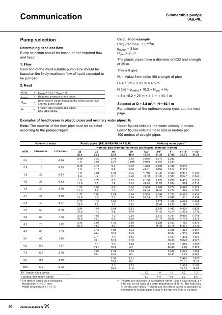
CommunicationSubmersible pumps<strong>SQE</strong>-<strong>NE</strong>Pump selectionDetermining head and flowPump selection should be based on the required flowand head.1. FlowSelection of the most suitable pump size should bebased on the likely maximum flow of liquid expected tobe pumped.2. HeadH [m] = p outlet x 10.2 + H geo + H fp outlet = Required pressure at the outletH geo =H f =Difference in height between the lowest water leveland the pump outletFriction loss in pipes and tubes.See table below.Calculation exampleRequired flow: 3.8 m 3 /hp outlet = 3 barH geo = 25 mThe plastic pipes have a diameter of ∅32 and a lengthof 25 m.This will give:H f = Value from table/100 x length of pipeH f = 18/100 x 25 m = 4.5 mH [m] = p outlet x 10.2 + H geo + H f= 3 x 10.2 + 25 m + 4.5 m = 60.1 mSelected at Q = 3.8 m 3 /h, H = 60.1 mFor selection of the optimum pump type, see the nextpage.Examples of head losses in plastic pipes and ordinary water pipes: H fNote: The material of the riser pipe must be selectedaccording to the pumped liquid.Upper figures indicate the water velocity in m/sec.Lower figures indicate head loss in metres per100 metres of straight pipes.Volume of water Plastic pipes* (PELM/PEH PN 10 PELM) Ordinary water pipes**m 3 /h Litres/min. Litres/sec.0.6 10 0.160.9 15 0.251.2 20 0.331.5 25 0.421.8 30 0.502.1 35 0.582.4 40 0.673.0 50 0.833.6 60 1.004.2 70 1.124.8 80 1.335.4 90 1.506.0 100 1.677.5 125 2.089.0 150 2.5010.5 175 2.92* The table is based on a monogram.Roughness: K = 0.01 mm.<strong>Water</strong> temperature: t = 10 °C.2520.40.491.80.764.01.06.41.310.01.5313.01.7716.02.0522.02.5437.03.0643.03.4350.0Nominal pipe diameter in inches and internal diameter in [mm]3226.20.300.660.461.140.612.20.783.50.934.61.086.01.247.51.5411.01.8515.02.0818.02.4725.02.7830.03.139.03.8650.090 ° bends, slide valves 1.0 1.0 1.1 1.2 1.3T-pieces, non-return valves 4.0 4.0 4.0 5.0 5.04032.60.190.270.30.60.390.90.51.40.61.90.692.00.803.30.994.81.26.51.348.01.5910.51.812.02.016.02.4924.03.0033.03.538.05040.80.120.0850.190.180.250.280.320.430.380.570.440.700.510.930.631.400.761.900.862.501.023.001.153.501.284.61.596.61.918.62.2311.01/2"15.750.8559.9101.28220.111.71033.532.13849.932.56569.342.99391.543/4"21.250.4702.4070.7054.8620.9408.0351.17411.911.40916.501.64421.751.87927.662.34941.402.81957.743.28876.491"27.000.2920.7840.4381.5700.5842.5880.7303.8340.8765.2771.0226.9491.1688.8201.46013.141.75118.282.04324.182.33530.872.62738.302.91946.493.64970.411 1/4"35.750.2490.4160.3310.6770.4151.0040.4981.3790.5811.8110.6642.2900.8303.4030.9964.7181.1626.2311.3287.9401.4949.8281.66011.902.07517.932.49025.112.90433.321 1/2"41.250.2490.3460.3120.5100.3740.7000.4360.9140.4991.1600.6231.7190.7482.3750.8733.1320.9973.9881.1224.9271.2475.9721.5588.9671.87012.532.18216.66** The data are calculated in accordance with H. Lang’s new formula, a =0.02 and on the basis of a water temperature of 10 °C. The head lossin bends, slide valves, T-pieces and non-return valves is equivalent tothe metres of straight pipes stated in the last two lines of the table.30


