Installation Operation Maintenance
Installation Operation Maintenance
Installation Operation Maintenance

You also want an ePaper? Increase the reach of your titles
YUMPU automatically turns print PDFs into web optimized ePapers that Google loves.
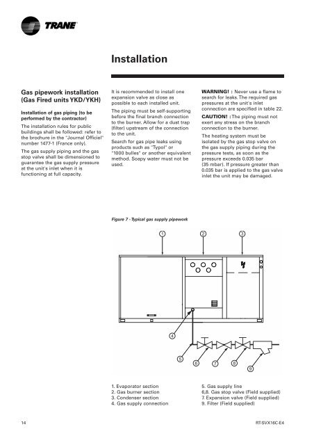
<strong>Installation</strong>Gas pipework installation(Gas Fired units YKD/YKH)<strong>Installation</strong> of gas piping (to beperformed by the contractor)The installation rules for publicbuildings shall be followed: refer tothe brochure in the "Journal Officiel"number 1477-1 (France only).The gas supply piping and the gasstop valve shall be dimensioned toguarantee the gas supply pressureat the unit's inlet when it isfunctioning at full capacity.It is recommended to install oneexpansion valve as close aspossible to each installed unit.The piping must be self-supportingbefore the final branch connectionto the burner. Allow for a dust trap(filter) upstream of the connectionto the unit.Search for gas pipe leaks usingproducts such as "Typol" or"1000 bulles" or another equivalentmethod. Soapy water must not beused.WARNING! : Never use a flame tosearch for leaks. The required gaspressures at the unit's inletconnection are specified in table 22.CAUTION! : The piping must notexert any stress on the branchconnection to the burner.The heating system must beisolated by the gas stop valve onthe gas supply piping during thepressure tests, as soon as thepressure exceeds 0.035 bar(35 mbar). If pressure greater than0.035 bar is applied to the gas valveinlet the unit may be damaged.Figure 7 - Typical gas supply pipework1. Evaporator section2. Gas burner section3. Condenser section4. Gas supply connection5. Gas supply line6,8. Gas stop valve (Field supplied)7. Expansion valve (Field supplied)9. Filter (Field supplied)14RT-SVX16C-E4