Installation Operation Maintenance
Installation Operation Maintenance
Installation Operation Maintenance

Create successful ePaper yourself
Turn your PDF publications into a flip-book with our unique Google optimized e-Paper software.
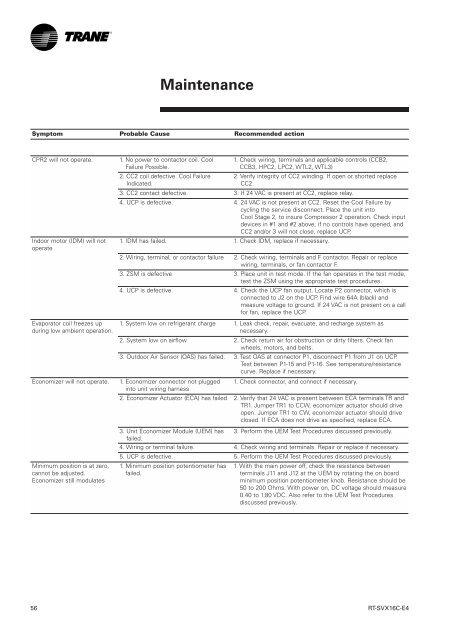
<strong>Maintenance</strong>Symptom Probable Cause Recommended actionCPR2 will not operate.Indoor motor (IDM) will notoperateEvaporator coil freezes upduring low ambient operation.Economizer will not operate.Minimum position is at zero,cannot be adjusted.Economizer still modulates1. No power to contactor coil. CoolFailure Possible.2. CC2 coil defective. Cool FailureIndicated.1. Check wiring, terminals and applicable controls (CCB2,CCB3, HPC2, LPC2, WTL2, WTL3)2. Verify integrity of CC2 winding. If open or shorted replaceCC2.3. CC2 contact defective. 3. If 24 VAC is present at CC2, replace relay.4. UCP is defective. 4. 24 VAC is not present at CC2. Reset the Cool Failure bycycling the service disconnect. Place the unit intoCool Stage 2, to insure Compressor 2 operation. Check inputdevices in #1 and #2 above, if no controls have opened, andCC2 and/or 3 will not close, replace UCP.1. IDM has failed. 1. Check IDM, replace if necessary.2. Wiring, terminal, or contactor failure 2. Check wiring, terminals and F contactor. Repair or replacewiring, terminals, or fan contactor F.3. ZSM is defective 3. Place unit in test mode. If the fan operates in the test mode,test the ZSM using the appropriate test procedures.4. UCP is defective. 4. Check the UCP fan output. Locate P2 connector, which isconnected to J2 on the UCP. Find wire 64A (black) andmeasure voltage to ground. If 24 VAC is not present on a callfor fan, replace the UCP.1. System low on refrigerant charge 1. Leak check, repair, evacuate, and recharge system asnecessary.2. System low on airflow 2. Check return air for obstruction or dirty filters. Check fanwheels, motors, and belts.3. Outdoor Air Sensor (OAS) has failed. 3. Test OAS at connector P1, disconnect P1 from J1 on UCP.Test between P1-15 and P1-16. See temperature/resistancecurve. Replace if necessary.1. Economizer connector not plugged 1. Check connector, and connect if necessary.into unit wiring harness2. Economizer Actuator (ECA) has failed 2. Verify that 24 VAC is present between ECA terminals TR andTR1. Jumper TR1 to CCW, economizer actuator should driveopen. Jumper TR1 to CW, economizer actuator should driveclosed. If ECA does not drive as specified, replace ECA.3. Unit Economizer Module (UEM) has 3. Perform the UEM Test Procedures discussed previously.failed.4. Wiring or terminal failure. 4. Check wiring and terminals. Repair or replace if necessary.5. UCP is defective. 5. Perform the UEM Test Procedures discussed previously.1. Minimum position potentiometer hasfailed.1. With the main power off, check the resistance betweenterminals J11 and J12 at the UEM by rotating the on boardminimum position potentiometer knob. Resistance should be50 to 200 Ohms. With power on, DC voltage should measure0.40 to 1.80 VDC. Also refer to the UEM Test Proceduresdiscussed previously.56RT-SVX16C-E4