

ASPIRE Spring 11 - Aspire - The Concrete Bridge Magazine
ASPIRE Spring 11 - Aspire - The Concrete Bridge Magazine
ASPIRE Spring 11 - Aspire - The Concrete Bridge Magazine

Create successful ePaper yourself
Turn your PDF publications into a flip-book with our unique Google optimized e-Paper software.
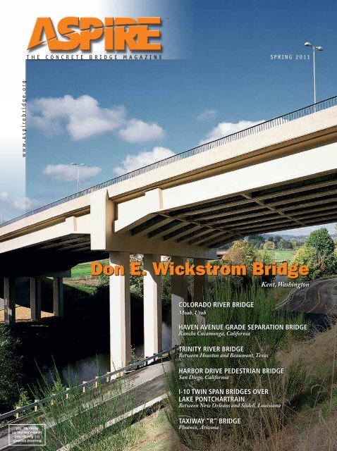
THE CONCRETE BRIDGE MAGAZINESPRING 20<strong>11</strong>www.aspirebridge.orgDon E. Wickstrom <strong>Bridge</strong>Kent, WashingtonCOLORADO RIVER <strong>Bridge</strong>Moab, UtahHaven Avenue Grade Separation <strong>Bridge</strong>Rancho Cucamonga, CaliforniaTrinity River <strong>Bridge</strong>Between Houston and Beaumont, Texasharbor drive pedestrian bridgeSan Diego, CaliforniaI-10 Twin Span <strong>Bridge</strong>s overLake PontchartrainBetween New Orleans and Slidell, LouisianaPresorted StandardU.S. Postage PaidLebanon Junction, KYPermit No. 567Taxiway “R” <strong>Bridge</strong>Phoenix, Arizona
Social, Economic, and Ecological Benefitsof Sustainable <strong>Concrete</strong> <strong>Bridge</strong>s6CONTENTSFeaturesBergerABAM 6One of the first firms involved with prestressed concrete looksto new innovations.Colorado River <strong>Bridge</strong> 14Utah’s first segmental bridge constructed from above tominimize impact on scenic national park.Haven Avenue Separation <strong>Bridge</strong> 18A world-class design utilizing precast concrete turns anunderpass bridge into a city attraction.Photo: BergerABAM.14Trinity River <strong>Bridge</strong> 22A combination of concrete solutions.Harbor Drive Pedestrian <strong>Bridge</strong> 26An iconic bridge for one of America’s finest cities.I-10 Twin Span <strong>Bridge</strong>s over Lake Pontchartrain 30Replacement of the I-10 Twin Span <strong>Bridge</strong>s overLake Pontchartrain.Taxiway “R” <strong>Bridge</strong> 34<strong>The</strong> evolution of the PHX Sky Train’s crossing of Taxiway“Romeo.”DepartmentsEditorial 2Photo: ©Figg <strong>Bridge</strong> Engineers.Photo: City of Rancho Cucamonga.18<strong>Concrete</strong> Calendar 4Perspective—Financially SustainableIndividual Mobility 10Aesthetics Commentary 17FHWA—Every Day Counts 38STATE—Idaho 40CITY—Middlebury, Vermont 44CCC—NEXT Beam <strong>Bridge</strong> 46Safety and Serviceability 48<strong>Concrete</strong> Connections 50AASHTO LRFD—20<strong>11</strong> Interim RevisionsRelated to <strong>Concrete</strong> Structures 52Photo: Tampa Hillsborough Expressway Authority.Advertisers IndexBentley Systems Inc. .................33CABA ............................... 3Dywidag-Systems International USA Inc..12Enerpac ............................49FIGG .................Inside Front CoverGRL Engineers Inc. ...................52Helser Industries ....................47Holcim Cement .....................25Larsa USA .........................13Mapei .............................29Mi-Jack Products .................... 21Parsons Brinckerhoff (PB) ......Back CoverPCI ..............................5, 43Poseidon Barge .....................37Reinforced Earth .................... 51T.Y. Lin International .... Inside Back CoverBeijing Wowjoint Machinery Co. .......45<strong>ASPIRE</strong>, <strong>Spring</strong> 20<strong>11</strong> | 1
EDITORIALPhoto: Ted Lacey Photography.When we started <strong>ASPIRE</strong> more than 4 years ago,none of the staff realized how much we woulddiscover about concrete bridges and their applications. Weknew that we wanted to present solutions that used cast-inplaceconcrete; precast, prestressed concrete; and segmentalconstruction. Within these broad categories, we have showna host of options: arches, box beam bridges, bulb-tee beambridges, cable-stayed bridges, I-beam bridges, spliced-girderbridges, stress ribbon bridges, and suspension bridges. Now,we even have new double-tee beam bridges (see page 46).We also set out with the goal of including transit andrailway bridges, pedestrian bridges, and aircraft runway ortaxiway bridges as well as highway bridges.In addition, concrete is no longer plain vanilla concrete!<strong>Bridge</strong>s can now be built with a variety of concretes:• High-performance concrete for durability• High-strength concrete to achieve longer spansand shallower beam cross sections• Lightweight concrete to reduce dead loads andprovide internal curing• Flowable concrete to make consolidation easier• Self-consolidating concrete to eliminate the needfor vibration to achieve consolidation• Ultra-high-performance concrete that willfacilitate a new generation of bridgesIn every issue, we include a variety of topics to illustratethe available options. We also show how bridges are built,particularly when there are environmental, traffic, space,or time restrictions that prevent the traditional methods ofconstruction from being used.<strong>The</strong> articles in this issue continue to meet our goals ofillustrating the many applications of concrete. On page 26,we feature a cast-in-place, horizontally curved pedestrianbridge. However, it is not as simple as that. <strong>The</strong> bridge is alsoa self-anchored suspension bridge supported by an inclinedmast. <strong>The</strong> author explains how equilibrium of forces wasmaintained and geometric compatibility was achieved.<strong>The</strong> Many Applications of <strong>Concrete</strong>Log on NOW at www.aspirebridge.org and take the <strong>ASPIRE</strong> Reader Survey.Precast/Prestressed <strong>Concrete</strong> InstituteHenry G. Russell, Managing Technical EditorAmerican Segmental <strong>Bridge</strong> Institute<strong>The</strong> Phoenix Sky Harbor International Airport isconstructing a 5-mile transit system to connect the variousairport facilities. This system crosses an active taxiwayrequiring a 340-ft main span using a cast-in-place, posttensioned,box-girder bridge (page 34).In the process of producing <strong>ASPIRE</strong>, we have also noticedthe pride that communities take in their bridges. Such isthe case of the grade-separation railway bridge in RanchoCucamonga, Calif., where the new bridge provides a citylandmark that complements the dramatic backdrop of themountains. See page 18.In this issue, we feature three highway bridges to showtheir diverse applications. <strong>The</strong> Trinity River <strong>Bridge</strong> in Texas,described on page 22, uses a combination of structuralsystems with precast, prestressed concrete beams for theapproach spans and variable depth, cast-in-place, twinsegmental box girders for the main spans. <strong>The</strong> ColoradoRiver <strong>Bridge</strong> in Moab, Utah, (page 14) is also a cast-inplace,twin segmental box-girder bridge, which is designedto blend with the surrounding environment.When it comes to quantities of concrete components,it is hard to compete with the new I-10 Twin Span<strong>Bridge</strong>s over Lake Ponchartrain in Louisiana (see page30). Four manufacturers were needed to produce thenecessary components for this bridge. <strong>The</strong> bridge had tobe constructed rapidly because the I-10 traffic was usingthe old bridge that had been patched together followingHurricane Katrina. And talking of rapid construction, readabout the FHWA Every Day Counts Initiative on page 38.None of these articles would be possible without theingenuity, creativity, and innovation of the bridgecommunity. To the authors of our articles, we offer a big“Thank you.”Don’t forget, we are always looking for innovativeapplications. If you have a project that you would like tohave considered, whether large or small, please contact usat www.aspirebridge.org and select “Contact Us.” We lookforward to hearing from you.Epoxy Interest GroupExecutive EditorJohn S. DickManaging Technical EditorDr. Henry G. RussellManaging EditorCraig A. ShuttEditorial AdministrationJames O. Ahtes Inc.Art DirectorPaul GrigonisLayout DesignTressa A. ParkAd SalesJim OestmannPhone: (847) 838-0500 • Cell: (847) 924-5497Fax: (847) 838-0555joestmann@arlpub.comReprint SalesPaul Grigonis(312) 360-3217e-mail: pgrigonis@pci.orgPublisherPrecast/Prestressed <strong>Concrete</strong> InstituteJames G. Toscas, PresidentEditorial Advisory BoardWilliam N. Nickas, Precast/Prestressed <strong>Concrete</strong>Institute (PCI)William R. Cox, American Segmental <strong>Bridge</strong> Institute(ASBI)David McDonald, Epoxy Interest Group (EIG)Dr. Henry G. Russell, Henry G. Russell, Inc.John S. Dick, J. Dick Precast <strong>Concrete</strong> Consultant LLCPOSTMASTERSend address changes to <strong>Aspire</strong>200 W. Adams St., Suite 2100Chicago, IL 60606.Standard postage paid at Chicago, IL, and additionalmailing offices.<strong>Aspire</strong> (Vol. 5, No. 2),ISSN 1935-2093 is published quarterlyby the Precast/Prestressed <strong>Concrete</strong> Institute200 W. Adams St., Suite 2100Chicago, IL 60606.Copyright 20<strong>11</strong>, Precast/Prestressed <strong>Concrete</strong> Institute.If you have a project to be con sidered for <strong>Aspire</strong>, sendinformation to <strong>Aspire</strong>200 W. Adams St., Suite 2100Chicago, IL 60606phone: (312) 786-0300www.aspirebridge.orge-mail: info@aspirebridge.orgCoverDon E. Wickstrom <strong>Bridge</strong> in Kent, WashingtonPhoto: BergerABAM.Silica Fume AssociationExpanded Shale Clay and Slate InstitutePortland Cement Association2 | <strong>ASPIRE</strong>, <strong>Spring</strong> 20<strong>11</strong>
CONTRIBUTING AUTHORSM. Myint Lwin is directorof the FHWA Office of <strong>Bridge</strong>Technology in Washington, D.C.He is responsible for the NationalHighway <strong>Bridge</strong> Programdirection, policy, and guidance,including bridge technologydevelopment, deployment andeducation, and the National<strong>Bridge</strong> Inventory and InspectionStandards.Dr. Dennis R. Mertz isprofessor of civil engineeringat the University of Delaware.Formerly with Modjeski andMasters Inc. when the LRFDSpecifications were first written,he has continued to be activelyinvolved in their development.Kenneth C. Saindon isa principal bridge engineerwith PBS&J, an Atkinscompany in Denver, Colo.He has 17 years of complexbridge project experienceencompassing aesthetics,durability, constructability,project management, and riskmanagement.CONCRETE CALENDAR 20<strong>11</strong>/2012For links to websites, email addresses, or telephone numbers for these events, go towww.aspirebridge.org and select “EVENTS.”April 18-19, 20<strong>11</strong>ASBI 20<strong>11</strong> Grouting CertificationTrainingJ.J. Pickle Research Campus<strong>The</strong> Commons CenterAustin, Tex.April 26-27, 20<strong>11</strong>ASBI Construction PracticesSeminarHyatt Harborside HotelBoston, Mass.May 1-3, 20<strong>11</strong>PTI Technical Conference &Exhibition<strong>The</strong> Westin Crown CenterKansas City, Mo.May 9-12, 20<strong>11</strong>World of Coal AshMarriott Tech CenterDenver, Colo.May 15-19, 20<strong>11</strong>AASHTO Subcommittee on <strong>Bridge</strong>sand Structures Annual MeetingMarriott Norfolk WatersideNorfolk, Va.October 16-20, 20<strong>11</strong>ACI Fall ConventionMillennium Hotel & Duke Energy CenterCincinnati, OhioOctober 22-25, 20<strong>11</strong>PCI Annual Convention andExhibition and National <strong>Bridge</strong>ConferenceSalt Lake City Marriott Downtown andSalt Palace Convention CenterSalt Lake City, UtahNovember 7-8, 20<strong>11</strong>ASBI 23rd Annual ConventionWashington Marriott Wardman ParkWashington, D.C.January 22-26, 201291st Annual MeetingTransportation Research BoardMarriott Wardman Park, OmniShoreham, and Hilton WashingtonWashington, D.C.March 18-22, 2012ACI <strong>Spring</strong> ConventionHyatt Regency DallasDallas, Tex.EXECUTIVE EDITORPhoto: Ted Lacey Photography.Frederick Gottemoelleris an engineer and architect,who specializes in the aestheticaspects of bridges and highways.He is the author of <strong>Bridge</strong>scape,a reference book on aestheticsand was deputy administratorof the Maryland State HighwayAdministration.John S. Dick is an engineeringconsultant who has beeninvolved with the design,application, and promotion ofprecast concrete for 41 years. Heformerly served with PCI stafffor 22 years.June 5-8, 20<strong>11</strong>International <strong>Bridge</strong> ConferenceDavid L. Lawrence Convention CenterPittsburgh, Pa.August 9-12, 20<strong>11</strong>Ninth International Symposium onHigh Performance <strong>Concrete</strong>Christchurch Convention CentreChristchurch, New ZealandSeptember 25-28, 20<strong>11</strong>Western <strong>Bridge</strong> Engineers’ Seminar(Abstract Proposals due April 22)<strong>The</strong> Arizona Grand ResortPhoenix, Ariz.October 2-6, 20<strong>11</strong>7th World Congress on Joints,Bearings and Seismic Systems for<strong>Concrete</strong> StructuresGreen Valley Ranch ResortLas Vegas, Nev.July 8-12, 20122012 AASHTO Subcommittee on<strong>Bridge</strong>s and Structures MeetingTexasSeptember 29–October 2, 2012PCI Annual Convention andExhibition and National <strong>Bridge</strong>ConferenceNashville, Tenn.October 21-25, 2012ACI Fall ConventionSheraton CentreToronto, Ontario, Canada4 | <strong>ASPIRE</strong>, <strong>Spring</strong> 20<strong>11</strong>
FOCUSBergerABAMContinues toPioneerby Craig A. ShuttA precast, prestressed concrete spliced girder design was used in the Don E. Wickstrom <strong>Bridge</strong> in Kent, Wash., to avoid any piers orfalsework in the river. <strong>The</strong> girders feature 60-ft-long variable-depth haunched segments balanced on the piers. All photos: BergerABAM.One of the firstfirms involved withprestressed concretelooks to newinnovationsIn the 1950s, the founders ofBergerABAM created a revolutionaryinstrumentation and testing procedureto validate the use of prestressedconcrete, thereby ushering in a newera for bridge construction. Today,the firm remains a leader in the useof prestressed concrete for a variety ofprojects, including routine and first-ofits-kindapplications for transportation,marine, and building structures. And,with its eye firmly set on the challengesfacing the industry, it plans to continueto innovate with concrete in the future.“<strong>Concrete</strong> is generally consideredmore durable than steel and requiresless maintenance, especially in a marineenvironment,” says Bob Fernandes, vicepresident of BergerABAM’s Public Works‘We have a design-for-construction mentalityand we enjoy overcoming obstacles.’& Transportation Department. “<strong>The</strong> useof prestressed concrete allows the useof longer spans when required.”Although clients benefit from the firm’stechnical expertise with concrete, theyare also looking for other qualities whenthey hire the firm, he says. “Each clientis different, but I suspect the qualitiesthey appreciate most are the onesthat our founders used to succeed:creativity and persistence. Our companywas founded by individuals who wereentrepreneurs and contractors. We havea design-for-construction mentality andwe enjoy overcoming obstacles.”Constructability is a critical ingredientfor today’s projects, he notes. “<strong>The</strong>need goes beyond a bridge’s actualdesign to include a strong sensitivityto environmental concerns. Due toan increasingly complex regulatoryenvironment, we are generally requiredto document the entire constructionprocess in great detail in order to securepermits for the project. Obviously, thisneeds to be done early in the processif the design is to be completed in anefficient manner.”In some cases, the firm is required toengineer aspects of the constructionprocess, which it previously left to thecontractor, to ensure the client canfollow through on commitments madeto the regulatory agency issuing thepermits.“Following through and helping thecontractor execute the design are alsoimportant,” adds Chuck Spry, seniorproject manager, with BergerABAM’sPublic Works & TransportationDepartment. “Wherever possible, wetry to be open to project improvementssuggested by contractors that areconsistent with the client’s goals forthe project and the permits. In somecases, we have been able to get permitsaltered to implement a contractor’sideas that benefit the project. As6 | <strong>ASPIRE</strong>, <strong>Spring</strong> 20<strong>11</strong>
‘As projectsbecome more complex. . . we need goodrelationships with thecontractor.’projects become more complex andhave more requirements, we need goodrelationships with the contractor toensure the design becomes reality.”Devising designs that meet all theowners’ needs has been foremost sincethe firm’s inception. BergerABAM’sheritage dates to 1951. <strong>Concrete</strong>Engineering Co., which wouldbecome <strong>Concrete</strong> Technology Corp.,was founded by brothers Art andTom Anderson. Using his innovativeinstrumentation (strain gauge) andtesting program, Art proved prestressedconcrete was reliable to early skepticson the Walnut Lane <strong>Bridge</strong> inPhiladelphia. Built during 1949 and1950, the bridge became famous forits first use of prestressed concrete ina structure built in the United States,leading to many more bridges using thisinnovative technique.Art’s work ultimately led to the foundingof Anderson, Birkeland, Anderson andMast, shortened to ABAM Engineersin 1966. It became an affiliate of <strong>The</strong>Louis Berger Group Inc. in the late1980s, creating BergerABAM. “<strong>The</strong>firm essentially was founded due to theWalnut Lane <strong>Bridge</strong>, and bridges havebeen a major focus of our work eversince,” says Bob Mast, senior principaland the last remaining namesake<strong>The</strong> Elwha River <strong>Bridge</strong> in Clallam County,Wash., combines a cast-in-place segmentalconcrete bridge with a precast concretepedestrian bridge hung beneath thestructure. <strong>The</strong> three-span bridge separatesvehicle traffic from pedestrians using theOlympic Discovery Trail.partner. (For more on the company’shistory, see the sidebar.)Long Spans Reduce ImpactLong spans are becoming more popularto reduce environmental impact andto simplify complex geometries atinterchanges, where ramps andjunctions create traffic congestion. Thishas been aided by the Washington StateDepartment of Transportation (WSDOT)devising its own precast concrete girdershapes, which it encourages designersto use.Longer spans and more slendergirders are heavier and more difficultto handle than shorter shallowergirders. This challenge has required theindustry to develop new engineeringpractices. Mast has added to thatbody of knowledge, having workedat BergerABAM for over 50 years,including serving as president from1972 to 1986. Among his contributionshas been intensive study to developstandards and procedures for handlinglong precast concrete beams to ensuretheir stability during transport anderection.“<strong>The</strong> ways that long and heavycomponents are shipped have reallychanged, which has had an impact onwhat’s possible for bridge designs,”Mast says. “<strong>The</strong>re is much moreavailability of specialized equipmentto ensure that large, complex piecescan be handled easily. When I began,the absolute limit for transportingcomponents on the highway was 60tons. Now it’s double that, and we’repushing 200-ft for long plant-madebeams.”An example of the creative use ofprecast concrete to construct longerspans is the Don E. Wickstrom <strong>Bridge</strong>,a precast concrete spliced-girder design,created for the City of Kent, Wash. Akey reason for selecting the precastconcrete option was that the city didnot want any piers, or even falsework,to impact the Green River. <strong>The</strong> site alsodid not have good access.<strong>The</strong> design allowed the deliveryand erection of precast concrete inreasonable sizes so they could be siteassembledinto the final structure. <strong>The</strong>bridge also required a curving alignmenton a 9% grade, adding challenges. <strong>The</strong>three-span bridge includes a 183-ft-longmain span using 7-ft-deep WSDOTsuper girders.<strong>The</strong> firm also uses cast-in-place concreteto build slender and longer spans. Acreative example is the State Route 509(SR 509) <strong>Bridge</strong> that spans I-705 and theOn the State Route 509 interchange that spans I-705 and the BNSF Railway track in Tacoma, Wash., BergerABAM created a curving, elevatedsingle point urban interchange, the first in Washington state and one of the first in the country. <strong>The</strong> structure features cast-in-place, posttensionedconcrete box girders with variable-depth webs.<strong>ASPIRE</strong>, <strong>Spring</strong> 20<strong>11</strong> | 7
BergerABAM value-engineered thedesign for a new bridge spanning SR520 in Redmond, Wash., to connecta new Microsoft campus with theoriginal one. Although the cityenvisioned a steel-plate girder bridge,BergerABAM used precast, prestressedconcrete girders, 83 in. deep withan 8-in.-thick, cast-in-place concretedeck. <strong>The</strong> large, flat surfaces providedlandscaping and trail amenities toenhance aesthetics.BNSF Railway mainline tracks in Tacoma,Wash. <strong>The</strong> bridge supports an elevatedsingle-point urban interchange (SPUI),the first elevated SPUI designed in thestate of Washington and one of the firstin the country. <strong>The</strong> superstructure is acast-in-place, post-tensioned concretebox girder with superelevation, variabledepthwebs, and complex geometry. Itshows the material’s ability to be formedinto almost any shape.<strong>The</strong> SR 509 <strong>Bridge</strong> created acombination of needs for long spans toclear railroad tracks, vertical clearancesover the railroad, and freewayrestricted design options, Spry says.Cast-in-place concrete girders withcurved exterior webs were used, withthe overall bridge measuring 340 ftwide and 320 ft long with scallopedcutouts. “We had to completely rethinkhow we prepare design drawings inorder to communicate the complexreinforcement requirements to thecontractor on this project,” he explains.“In retrospect, this was really an earlyexample of using computers to createthree-dimensional models of thestructure in order to build it.”Speed Becomes a FocusIn all types of projects, the designersare seeing more emphasis on speed ofconstruction to minimize user costs andtraffic congestion. <strong>The</strong> firm’s focus onconstructability aids this process.BergerABAM is taking that focus furtherthrough a grant from the FederalHighway Administration’s Highwaysfor LIFE Technology PartnershipsProgram. <strong>The</strong> grant is being used todevelop a precast pier system foraccelerated bridge construction (ABC)in high-seismic areas. Dr. Lee Marsh,seismic specialist with BergerABAM,is managing the project, with a teamcomprising WSDOT, the University ofWashington, <strong>Concrete</strong> TechnologyCorp., and TriState Construction.A demonstration project for the piersystem will be constructed for WSDOTin 20<strong>11</strong>.Marsh is also leading a team that isdeveloping a synthesis of practice forthe National Cooperative HighwayResearch Program in Washington,D.C. <strong>The</strong> synthesis will summarize theinnovative techniques for applying ABCconcepts in moderate to high-seismicareas and will recommend the nextsteps the bridge industry should take tomake ABC a reality in these areas.<strong>The</strong> firm recently completed a notableproject in Redmond, Wash., in which<strong>The</strong> ways that longand heavy componentsare shipped have reallychanged.additional attention was paid toaccelerating construction while creatinga dramatic design. BergerABAM deviseda unique design for a roadway thatcrossed SR 520 at a skew of 70 degrees.Offset spans allowed the structuralframing to be skewed at 30 degreesand provided additional surface areafor landscaping and park-like amenities.<strong>The</strong> resulting design was a cost-effectivesolution that ideally suited the goal ofthe project, which was to connect theMicrosoft campuses on both sides of SR520.To speed construction, precast concretecolumns were used, minimizingconstruction time for an intermediatepier in the medians. “High-seismicforces require close attention to theconnections,” says Spry. Meeting thoserequirements, while also incorporatingABC concepts, necessitates the properbalance to ensure all needs are met.8 | <strong>ASPIRE</strong>, <strong>Spring</strong> 20<strong>11</strong>
<strong>The</strong> Tacoma Spur, designed by BergerABAMfor the Washington State Departmentof Transportation, involved more than14,500 lineal ft of elevated post-tensionedconcrete box girder freeway bridges anda complex interchange connecting thedowntown business district with I-5 inTacoma, Wash. <strong>The</strong> design included 2200linear ft of retaining wall on a difficultsloping site.Innovations Continue<strong>The</strong> firm continues to look toinnovative approaches, includingcombining materials and girder typesto create the most effective designs.“We’re combining post-tensionedconcrete box girders on end spansand precast, prestressed concretegirders over waterways more oftento meet individual project needs,”says Fernandes. Recently, designerscombined 210-ft-long, post-tensionedconcrete box girders over a railroadsite with precast, prestressed concretegirders for the approaches.In the case of the Elwha River <strong>Bridge</strong>in Clallam County, Wash., the firmcombined precast concrete and cast-inplaceconcrete to achieve multiple usergoals. <strong>The</strong> bridge features cast-in-placesegmental concrete spans that support aprecast concrete pedestrian bridge hungbeneath the main structure.<strong>The</strong> bridge was built with two endspans of cast-in-place concrete formedon falsework while two center,cantilevered sections were placed with aform traveler. For the pedestrian bridgeunderneath, which connects to theOlympic Discovery Trail, precast concretepanels were suspended from the mainsuperstructure, while precast concretedeck bulb-tee girders were used forthe section that runs perpendicular tothe main structure. (For more on thisproject, see the <strong>Spring</strong> 2010 issue of<strong>ASPIRE</strong>.)“We’re proud of the way we’recombining materials to maximize theireffectiveness and eliminate expansionjoints,” says Fernandes. “We primarilyuse precast, prestressed concretegirders and post-tensioned concretebox girders, but there are many ways tocombine those to get the most out ofthem.”Innovative designs will continue to berequired, Spry notes, but BergerABAM’sdesigners are up to the challenges.“<strong>The</strong>re are a lot of people here whohave spent all of their careers with thecompany, even though they had a lotof other options. That’s one reason wehave succeeded. Each generation haspassed down its knowledge and createda strong working environment that givesus continuity and encourages us toinnovate.”For additional photographs orinformation on this or other projects,visit www.aspirebridge.org and openCurrent Issue.BergerABAM completed a type, size, and location study and prepared plans, specifications,and cost estimates for the replacement of two bridges and approach roadway along ValleyAvenue in Tacoma, Wash. <strong>The</strong> new 662-ft-long, four-span, Valley Avenue <strong>Bridge</strong> designincludes a 215-ft-long, cast-in-place, post-tensioned concrete box girder main span thatcantilevers 30 ft beyond piers to support the ends of precast, prestressed concrete girderapproach spans.Prestressed <strong>Concrete</strong>Inspires BergerABAMArthur Anderson learned about thepotential of prestressed concrete whileproviding instrumentation for the150-ft-long, full-scale test beam used forthe Walnut Lane <strong>Bridge</strong> in Philadelphia,Pa., in 1949. That insight eventually led tothe founding of ABAM.Seeing opportunity, Anderson joined withhis brother Tom, also a contractor, to form<strong>Concrete</strong> Engineering Co. That companylater became <strong>Concrete</strong> Technology Corp.,a precast concrete manufacturer thatremains an industry leader. <strong>The</strong> brothers,both with advanced engineering degrees,discovered they were conflicted out ofbidding on engineering projects, so theycreated a sister company called Anderson& Anderson Consulting Engineers todesign prestressed concrete projects.<strong>The</strong> firm thrived by creating small,prestressed concrete bridges for loggingcompanies that originally constructed onlyshort-term timber bridges. “It’s alwaysmore difficult to introduce new ideas tolarge groups, so the smaller the unit, theeasier new ideas will be accepted,” saysBob Mast, senior principal, about startingout on small projects. From there, the firmdeveloped strong relationships with anumber of city and county officials, whotook advantage of the company’s turnkeycapabilities and innovative approaches.Hal Birkeland joined the firm in 1957 asa partner, and Mast joined in 1959 as ajunior engineer, becoming a partner in1963. <strong>The</strong>y became Anderson, Birkeland,Anderson and Mast, creating ABAMEngineers. A downturn in two keymarkets—offshore and transit—duringthe late 1980s led to the affiliation with<strong>The</strong> Louis Berger Group Inc., which owns51% of the firm’s stock, with the restowned by BergerABAM key employees.Today, BergerABAM operates six offices(Federal Way, Seattle, and Vancouver,Wash.; Portland, Ore.; Las Vegas, Nev.; andHouston, Tex.) with over 200 employees.In addition to its transportation (roadway,bridge, and transit) department, it alsooperates waterfront and marine, offshoreand energy, building, planning, and naturalresources, construction administration,and underwater services sectors. Revenuesare approximately $37.4 million.<strong>ASPIRE</strong>, <strong>Spring</strong> 20<strong>11</strong> | 9
PERSPECTIVEFinancially SustainableIndividual MobilityEquating benefits and costs via pricing systemsby Kenneth C. Saindon,PBS&J, an Atkins companyYou have to love the irony—transportation is at a crossroads!Why? Because aggregate demandfor individual mobility has renderedthe traditional funding mechanismfor surface transportation, the federalgas tax, obsolete. Unsustainable bestdescribes this funding mechanism, in itscurrent form, to meet current and futuremobility demands. Individual mobility isthe freedom of where to go, when togo, and how to go; the challenge to thetransportation industry is how best tomeet the demand for individual mobilityin a financially sustainable manner.“Free” MobilityGeneral highway mobility and thecongestion experienced in many areasrepresent a classic case of economicsrelated to “free” resources. <strong>The</strong>perception to drivers that drivingon highways is “free” causes trafficcongestion, with highway capacitybeing the resource in short supply. It isnot difficult to see why highway mobilitydemand is growing. <strong>The</strong> individualfreedom offered by traditional highwaymobility is unmatched in terms ofunrestricted arrival/departure times anddestinations, scalability to group size, allweatheroperation, protection of usersfrom the elements, and accommodationof personal belongings (e.g., groceries orrecreational equipment). From this reality,demand management strategies that seekto equate supply and demand via pricingsystems represent the best practice foraccommodating individual mobility in afinancially sustainable manner. Althoughan increase in the federal gas tax wouldgenerate more revenue, it does notpermit the establishment of equilibriumbetween supply and demand that wouldnaturally develop through the use of apricing system.Selmon Expressway with Tampa, Fla.,skyline. Photo: Tampa HillsboroughExpressway Authority.Cost Versus BenefitSustainability in transportation hasthus far focused almost exclusively onthe cost side of the mobility equation.Increased effort has been spentrecently on discernment of incremental“impacts” to the environment. <strong>The</strong>seare used in part as a means to justifyeverything from subsidizing transit withfederal gas tax revenues, to growthboundaries, and to transit-orienteddevelopment (including high-densityhousing). Nevertheless, the only sanedefinition of sustainability related tothe cost side of the mobility equation isadopting lowest life-cycle costing andasset management methodologies.What about the benefit side of themobility equation? Is there a way toquantify the benefits of individualmobility? Quantification of the mobilitybenefit via pricing systems wouldenable appropriate decision makingregarding future expenditures, such ashow much capacity should be addedand what mode or modes should beadvanced. Many fine examples offinancially sustainable transportationincorporating pricing systems supportthe hypothesis that users value theirindividual mobility highly. So what doesfinancially sustainable individualmobility look like?Selmon ExpresswayPerhaps the best example of financiallysustainable transportation that respondsto individual mobility demand isthe Tampa Hillsborough ExpresswayAuthority (THEA) Selmon Expresswayin Tampa, Fla. <strong>The</strong> Selmon Expresswayis an important east-west link neardowntown Tampa funded entirely with10 | <strong>ASPIRE</strong>, <strong>Spring</strong> 20<strong>11</strong>
user fees since its inception in 1976.Elevated reversible express lanes (REL)were added to the median in 2005,ushering in the use of electronic tollcollection for the REL and conversionof the local lanes to electronic tolling in2010. <strong>The</strong> Selmon Expressway has metprojected traffic and revenue data andcurrently generates revenues in excessof annual operation and maintenance(O&M) expenses, with excessesreinvested in other transportationprojects within THEA’s jurisdiction.<strong>The</strong> REL currently operates at freeflow conditions. Variable-price tolling(congestion pricing) has been discussedfor the REL should the need arise in thefuture to maintain free-flow conditions.<strong>The</strong> successful financial performanceof the Selmon Expressway is strongevidence of the effectiveness of pricingsystems. By adopting tolling from thebeginning, the Selmon Expressway hasbeen able to respond to user demandvia a pricing system that provides asustainable revenue stream.Summary<strong>The</strong> time has come for thetransportation industry to reprioritizepublic perception of individualmobility, particularly with respectto the often overlooked benefit.Individual mobility is not a luxury, it isa necessity. In the modern exchangeeconomy, individual mobility is on parwith energy in terms of importanceto the modern fabric of life. Demandfor individual mobility continues toWeekend individual mobility demand in theI-70 Mountain Corridor; westbound lookingeast near El Rancho, Colo., January 15, 20<strong>11</strong>.Photo: Kenneth C. Saindon.Other OpportunitiesAre there other opportunities toimplement financially sustainableindividual mobility? You bet! Neverbefore has there been a more idealopportunity to embrace similarfinancially sustainable mobility thanthe I-70 Mountain Corridor in centralColorado. Peak weekend travel demandin this corridor, between metro Denverand Glenwood <strong>Spring</strong>s, is primarilycomprised of recreational travel withsignificant unmet travel demandcurrently and in the future. Weekendrecreational travel demand is typicallydouble that of weekday demand for allother purposes combined (i.e., excludingrecreation). <strong>The</strong> addition of reversible,variable-price high occupancy/toll(HOT) lanes to supplement the existing“free” general purpose lanes is an idealsolution to pay for the construction ofthe HOT lanes (likely elevated in certainsegments) and assure a steady revenuestream for ongoing O&M expenses inthe corridor. A transit alternative hasbeen proposed for this corridor despitethe fact that such an alternative, evenheavily subsidized by highway users, willnot benefit individual mobility in thiscorridor given the recreational nature ofthe travel demand.Concept rendering of elevated HOT lane facility in I-70 Colorado Mountain Corridor. Image:©Kenneth C. Saindon.grow, and the transportation industryneeds to respond to this demand byfacilitating individual mobility becausethe individual is the ultimate client weserve. Institution of pricing systemsto attain financial sustainability is theindustry’s best path forward to achievingprominence in the modern exchangeeconomy. Mode choice and the splitof future expenditures across modesshould be determined via pricingsystems to ensure financial sustainability.Elimination of mode subsidies is implicitin such pricing systems.A financially sustainable model fortransportation, applicable to all modes,would include the following:• Pricing systems• Maximizing individual mobility• Minimizing cost through life-cyclecosting and asset managementmethodologies• Clean accounting, whereby eachmode must pay for itselfReference: Economics in One Lesson,Henry Hazlitt, 1946; reproducedby Ludwig von Mises Institute byarrangement with Three Rivers Press,2008.Acknowledgement: <strong>The</strong> author wishesto thank Sue Chrzan, communicationsmanager of the Tampa HillsboroughExpressway Authority, for informationand photographs of the SelmonExpressway. Chrzan may be reachedat (813) 272-6740 or through theauthority’s website at www.tampa-xway.com.Editor’s Note<strong>The</strong> above article presents the opinionsof the author and not necessarily thoseof the publisher and sponsors of <strong>ASPIRE</strong>.We welcome comments that contribute to allperspectives concerning this article. Emailinfo@aspirebridge.org.<strong>ASPIRE</strong>, <strong>Spring</strong> 20<strong>11</strong> | <strong>11</strong>
12 | <strong>ASPIRE</strong>, <strong>Spring</strong> 20<strong>11</strong>
PROJECTInHarmonywithNatureby Fred Doehring, Utah Department ofTransportation and Stephen E. Fultz,Figg <strong>Bridge</strong> EngineersConstruction was completed in December 2010, on the U.S. 191 Colorado River <strong>Bridge</strong> inMoab, Utah, the state’s first concrete segmental bridge. <strong>The</strong> bridge’s sustainable design keptthe focus on the natural wonder of the environment. All photos: ©Figg <strong>Bridge</strong> Engineers.Utah’s firstsegmental bridgeconstructed fromabove to minimizeimpact on scenicnational park<strong>The</strong> new U.S. 191 <strong>Bridge</strong> over theColorado River in Moab, Utah, blendswith the spectacular Canyonlandsregion and offers a number of featuresto ensure that the landscape remainedpristine during and after construction.<strong>The</strong> state’s first segmental concretebridge was constructed in a way thatallowed continual recreational use ofthe river and surrounding area duringconstruction. Long spans ensured aminimal bridge footprint, while a uniquepublic involvement process provided acontext-sensitive design representativeof the community’s vision.<strong>The</strong> pristine environment surroundingMoab was acknowledged in thesolution by the Utah Department ofTransportation (UDOT) and Figg <strong>Bridge</strong>Engineers. <strong>The</strong> twin, 1022-ft-longbridges consist of cast-in-place, posttensionedconcrete segmental structuresbuilt from above using the balancedcantilever method of construction toprotect the environment. Piers andabutments were staggered 38 ft toalign the substructure with the riverflowdirection, which is skewed to theroadway alignment. <strong>The</strong> bridges are 39ft 10 in. wide including two 12-ft-widelanes, a 7-ft-wide outside shoulder anda 6-ft-wide inside shoulder. Pedestrians,mountain bikers, and casual riders areseparated from the highway trafficby using a new pedestrian bridgeupstream.Unique Site Characteristics<strong>The</strong> bridge is in one of the most highprofilelocations in the region, drawingmore than 1.5 million visitors a year toits picturesque landscapes. It providesa gateway to Arches National Park,Canyonlands National Park, Dead HorsePoint State Park, and the Sand FlatsRecreation Area.Designated wetlands along the southbank required careful consideration. Inaddition, water levels in the river can varygreatly, historically causing flooding of theMoab Valley. Flows in excess of 100,000ft 3 /sec have been recorded at the bridgesite. <strong>The</strong> design had to accommodateseasonal variations in water-surfaceelevation of more than 15 ft. A sitespecifichydraulic analysis completed forthe project ensures that the new bridgeprofile14 | <strong>ASPIRE</strong>, <strong>Spring</strong> 20<strong>11</strong>colorado river bridge / moab, utahEngineer: Figg <strong>Bridge</strong> Engineers, Denver, Colo.CONSTRUCTION ENGINEERing inspection: Figg <strong>Bridge</strong> Engineers, Denver, Colo.CONSTRUCTION ENGINEER: Summit Engineering Group Inc., Littleton, Colo.Roadway engineers: Lochner, Salt Lake City, Utahsurvey, row, and geotechnical engineering: RB&G Engineering, Provo, UtahPRIME CONTRACTOR: Wadsworth Brothers Construction, Draper, UtahCONCRETE SUPPLIER: Legrand Johnson, Moab, UtahPost-tensioning contractor: Dywidag-Systems International USA Inc., Bolingbrook, Ill.
will survive the predicted 500-yearevent. <strong>The</strong> river also is home to severalendangered fish species. Constructionactivities that disturb the river cannotbe conducted during the fish-spawningseason of May through August.Segmental SolutionTo meet these challenges, a threespan,segmental bridge was selectedusing cast-in-place, single cell, concretetrapezoidal box girders. <strong>The</strong> spansconsist of two 292-ft-long end spansand a 438-ft-long main span. <strong>The</strong>superstructure depth varies from 19 ft2½ in. to 9 ft 2½ in. <strong>The</strong> deck variesin thickness from <strong>11</strong>½ in. at the centerand wing tips to 1 ft 8½ in. over thewebs. <strong>The</strong> deck thickness includes a 2½in. integral wearing surface. Webs aretypically 1 ft 2 in. thick, and the bottomslab varies in thickness from 9 in. atmidspan and near the abutments to 3 ft0 in. at the piers.<strong>The</strong> design creates open space beneaththe bridge and minimizes its footprint.Only one pier of each structure islocated in the river, strategically placedto maintain the navigational channel.<strong>The</strong> other pier is located well outside thechannel and adjacent wetlands, whichstreamlined the permitting process. Longside spans allow enhanced and new trailsbeneath the bridge at each end.Building from above using balancedcantilevers, construction began with45-ft-long sections of the superstructureatop each pier. <strong>The</strong>se “pier tables” serveas launching points for form travelersthat advance horizontally away fromeach pier to construct segments of thebridge. Casting in an alternating fashion,first on one side of the pier and then onthe other, ensured that pier-constructionloads remained balanced.<strong>The</strong> segmental concrete designeliminated the need for large groundbasedequipment, which wouldhave been difficult to place. <strong>The</strong> riverconditions are often less than 5 ft deepin winter and more than 20 ft deepin summer. This would have madeconstruction of other bridge typesdifficult. UDOT also benefited from thesustainable, low-maintenance natureof this bridge type, which featuresbi-directional post-tensioning.Substructuresand Materials<strong>The</strong> southbound bridge was constructedadjacent to the existing bridge, whichcontinued in operation during thisinitial phase. <strong>The</strong> work began with 7-ftdiameter, 150-ft-long drilled shafts for theland pier (Pier 3) using polymer slurry. <strong>The</strong>7-ft-diameter, 100-ft-long shafts for Pier 2in the river were installed after completionof a cofferdam and used oscillatorcasings.Footings at the piers are 30 ft squareand 8 ft thick. A mass concrete planFeatures ensuredthat the landscaperemained pristine duringand after construction.ensured controlled thermal stresses arisingfrom the heat of hydration. A 4000 psicompressive strength concrete with TypeII cement mixture and 30% Class F fly ashwas specified for piers and foundations.<strong>Concrete</strong>s were tested for chloridepermeability to make sure they fell withinthe “low” range for long-term durability.Cylindrical columns 24 ft in diameterwere selected for aesthetics and tofacilitate a four-bearing configuration,eliminating the need for temporaryworks during cantilever construction. <strong>The</strong>circular profile also enhanced pier-shapecharacteristics against the river flow. Pierswere cast hollow and filled with concreteflow-fill, eliminating mass concreteconcerns. Pier 2 on the south bank is 13ft tall, while Pier 3 in the river is 33 ft tall.<strong>The</strong> construction of a temporarycauseway and work trestle over thefloodplain and river was completed as thefoundation work progressed. It had to beaccomplished before the May-to-Augustrestriction on work in the river began dueto fish habitat concerns.Balanced cantilever constructionextended out from both sides of thesingle river pier to create long, archingspans of 438 ft over the water thatprotected the environment below.TWIN, 1022-FT-LONG, THREE-SPAN SEGMENTAL CAST-IN-PLACE CONCRETE BOX-GIRDER BRIDGES / UTAHDEPARTMENT OF TRANSPORTATION, OWNERreinFORCIng STEEL: Masco Inc., Centerville, UtahEpoxy-coated reinforcing steel: Western Coating, Ogdan, UtahForm Travelers: NRS-USA, Aventura, Fla.bridge description: Twin, three-span, cast-in-place concrete segmental box-girder bridges with end spans of 292 ft and a center span of 438 ft,built with form travelers to minimize impact on the environment<strong>Bridge</strong> Construction Cost: $25.9 millionawards: Roads & <strong>Bridge</strong>s Top Ten, 2010<strong>ASPIRE</strong>, <strong>Spring</strong> 20<strong>11</strong> | 15
Only one pier of the 1022-ft-longstructure is located in the river,strategically placed to maintain thenavigational channel preferred byrecreational users. <strong>The</strong> other pier islocated well outside the channel andadjacent wetlands.SuperstructureA minimum concrete compressivestrength of 6000 psi was required bythe design with high-performanceconcrete specified to ensure long-termdurability. <strong>The</strong> concrete contained30% Class F fly ash and was pumpedfrom the shore area and from thework trestle as needed. <strong>The</strong> segmentswere 16 ft 6 in. long. <strong>Concrete</strong> wascured in all weather conditions usingcuring compound, heating, andinsulating blankets. High early strengthconcrete was critical to the contractor’sproduction schedule, with stressing andtraveler-launching strengths achieved inless than 36 hours.span. Transverse tendons in the deckcomprised 4 x 0.6-in.-diameter strandsspaced typically at 3 ft 3 5 ⁄8 in. centers.Cost-Effective DesignA cost-plus-time format determinedthe winning bidder in accordancewith UDOT’s statewide focus onaccelerated bridge construction.<strong>The</strong> low bid saved UDOT $3.1million compared to the engineer’sestimate. <strong>The</strong> bid schedule of 659days was met with 18 days to spare,completing work in early December2010. That was accomplisheddespite construction taking placeduring the coldest Moab winter inmore than 40 years, with consistentbelow-zero temperatures.<strong>Bridge</strong> Blends In<strong>The</strong> bridge’s aesthetic goals weredesigned to blend the structure withthe scenery as much as possible ratherthan allow it to serve as a focal point.To achieve this, a special mineral-basedLong, sweeping spans, stone textures on the piers, smooth barrier details, and bridgecolors were selected by the Moab community during special feedback sessions early inthe design process.Once the southbound bridge wasconstructed, the original structure wasdemolished and the northbound bridgewas built in its location, following thesame procedure. <strong>The</strong> form traveler andforms were used for the 6-ft closuresegments joining the cantileverstogether over the river. End sections ofthe bridge were cast on falsework ateach abutment.<strong>The</strong> closure segment in Span 1, onthe south side, was completed first,followed by the Span 3 segment on thenorth side. Finally, the main-span closurewas completed in Span 2. Once closureswere cast, the continuity tendons werepost-tensioned.Post-TensioningLongitudinal top-slab cantilever posttensioningtendons were embeddedin the deck and anchored on eachsegment face. Fifty 12 x 0.6-in.-diameterstrand tendons were used in eachcantilever, with 25 over each girderweb. Six 27 x 0.6-in.-diameter strandexternal continuity tendons were usedin the box girder, three per web, in eachspan. Bottom slab continuity tendonsconsisted of 12 x 0.6-in.-diameterstrands embedded in the bottom slabwith 6 tendons used in the end spansand 14 tendons used in the main<strong>The</strong> bridge incorporates a special mineral-based stain that reacts with the concrete tobring out its natural texture and color. Extra care was taken to achieve the ideal color,as the scenery coloration changes throughout the day and year with the sun’s positionand season.16 | <strong>ASPIRE</strong>, <strong>Spring</strong> 20<strong>11</strong>
stain that reacts with concrete wasused to bring out the natural textureand color of the concrete. Extra carewas taken to achieve the ideal color,as the scenery coloration changesthroughout the day and year with thesun’s position and season. Formlinersalso were used to create a rock textureon the mechanically-stabilized earth wallpanels and piers matching the textureof nearby canyon wall relief, providinga natural rock appearance for river andtrail users.Long concrete spans, efficientlycombined with post-tensionedsegmental technology, resulted ina delicate footprint, and buildingfrom above protected the cherishedenvironment during construction.Balanced cantilever construction allowedfor continual recreation on the river,which was important to this region ofoutdoor enthusiasts. <strong>The</strong> cast-in-placesegmental post-tensioned concretebox girders will offer long service life,resulting in low life-cycle cost for thecitizens of Utah.__________Fred Doehring is deputy bridge designengineer for the Utah Department ofTransportation in Salt Lake City, Utah,and Stephen E. Fultz is assistant regionaldirector with Figg <strong>Bridge</strong> Engineers inDenver, Colo.For additional photographs orinformation on this or other projects,visit www.aspirebridge.org and openCurrent Issue.Visual SensitivityA guiding theme of “A <strong>Bridge</strong> in Harmony with Nature” shaped the context-sensitive design. A stakeholdergroup representing the community guided the design to ensure realization of the community’s vision.Stakeholders included in the discussions included city and county leaders, property owners, businesses, theLions Club, the Bureau of Land Management, the National Park Service (including Arches), and the MoabTrails Alliance.<strong>The</strong> arching shape of the variable-depth superstructure reflects the spirit of nearby Landscape Arch, aprominent feature in Arches National Park. <strong>Bridge</strong> piers were located to avoid the trail network, andoverhead construction allowed trail use and many recreational events to continue during construction.AESTHETICSCOMMENTARYby Frederick GottemoellerLow and close to the Colorado River, surrounded by stunning high desert buttes androck formations, this bridge occupies a very small part of the total visual field. Its designerswere wise to design it so that it seems to be an integral part of the topography. Itsmost obvious feature, its color, captures the color of the surrounding rocks perfectly.But, there’s more. <strong>The</strong> girder is very well proportioned. <strong>The</strong> significant difference ingirder depth between haunch and midspan, and end spans makes visible the concentrationof forces over the piers. <strong>The</strong> clear desert sunlight causes the overhang to cast adeep shadow across the top of the girder that makes the midspan and end spans seemeven thinner. <strong>The</strong> piers are too short to make a visual statement on their own, so thedesigner has not made the attempt. Instead, the piers have been designed as simple cylinders.<strong>The</strong>y are notched at their tops and seem to cradle the haunches. As a result, theyact as visual foils for the girder. <strong>The</strong>ir visual mass contrasts with the relative thinness ofthe girder, reinforcing its delicate appearance.Because the bridge is so low to the water, the view of the bridge interacts with its ownreflection, which reinforces initial impressions. Altogether the bridge seems delicate,almost liquid, a fitting contrast to the robust formations in the background.<strong>Bridge</strong>s don’t always have to be foreground elements. Sometimes it is best when theyjust blend in, become a part of a beautiful scene that was strong before they got there,and is strong still.Snow covers the mountain landscape in Moab, showcasing the elegant, gracefulcurves of Utah’s longest concrete bridge span.<strong>ASPIRE</strong>, <strong>Spring</strong> 20<strong>11</strong> | 17
Rancho Cucamonga’sHaven Avenue Grade Separation <strong>Bridge</strong>by Miguel A. Carbuccia and Sam S. Xie, PBS&J, an Atkins companyA world-class design utilizing precast concrete turns an underpassbridge into a city attraction<strong>The</strong> award-winning Haven AvenueGrade Separation <strong>Bridge</strong> has becomea stunning new landmark in RanchoCucamonga, Calif. Built with precastconcrete, the colorful and innovativebridge has remedied multiple problems,including massive traffic congestion.By using architecturally enhancedprefabricated concrete elements, inthe hands of a highly effective team,the project was completed aheadof schedule and under budget. Thisproject puts to rest the notionthat bridge underpasses have to beutilitarian to meet schedule andbudgetary constraints.Rancho Cucamonga lies at the base ofthe picturesque San Gabriel Mountainsand is located roughly 39 miles east ofLos Angeles. <strong>The</strong> city’s population hasgrown by about 35% in the last decadedue in large part to two east-westhighways—I-10 and State Route 210—that traverse the city. <strong>The</strong>se highwaysare connected perpendicularly by HavenAvenue, a six-lane divided arterial thatleads to Rancho Cucamonga’s city center.Increasing traffic and demand fortransportation services have also grownalong with the city’s population. <strong>The</strong>Metrolink commuter train and BurlingtonNorthern Santa Fe (BNSF) tracksintersected Haven Avenue at grade nearthe freeway interchanges. In recent years,rail service has increased to roughly 40trains per day, which resulted in longtraffic delays for the nearly 20,000 dailymotorists traveling north and south onHaven Avenue. Before the bridge wasbuilt, vehicular traffic idled roughly 64minutes daily, while emitting about2.5 tons of carbon dioxide into theatmosphere.<strong>The</strong> solution was to separate vehicleand train traffic by lowering the HavenAvenue roadbed by 28 ft and building<strong>The</strong> Haven Avenue Grade Separation<strong>Bridge</strong> stands as a dramatic addition tothe City of Rancho Cucamonga, Calif.Photo: City of Rancho Cucamonga.profile18 | <strong>ASPIRE</strong>, <strong>Spring</strong> 20<strong>11</strong>haven avenue grade SEPARATION bridge / rancho cucamonga, california<strong>Bridge</strong> Design Engineer: PBS&J, an Atkins company, Orange, Calif.roadway design and general engineering services: URS Corporation, Santa Ana, Calif.prime contractor: KEC Engineering, Covina, Calif.beam precaster: Pomeroy Corporation, Perris, Calif., a PCI-certified producerpilaster, balustrade, and medallion precaster: QuickCrete, Norco, Calif.cast-in-place concrete supplier: Chaparral <strong>Concrete</strong> Company, Glendora, Calif.post-tensioning contractor: Dywidag-Systems International USA Inc., Long Beach, Calif.
<strong>The</strong> tops of the piers, which supported the beams, were flared to match thearch shape. Seats on the noses of the piers will receive the precast concretepilasters. Photo: PBS&J, an Atkins company.an underpass bridge to support the twotrain tracks. Instead of a typical bridgeunderpass, the city and its residentswanted a monumental gateway to thetown center.<strong>The</strong> Haven Avenue underpass bridgewas planned to be built less than amile away from Rancho Cucamonga’snew city hall along a corridor that isemerging as a retail and commercial hub.<strong>The</strong> aesthetic treatment of the bridgewas extremely important, though thecity had a relatively low budget of $28million for the entire bridge and roadwayseparation project. Furthermore, in orderto minimize traffic disruption, the bridgeneeded to be built quickly.A Landmark Design withPrecast <strong>Concrete</strong><strong>The</strong> innovative design for the HavenAvenue <strong>Bridge</strong> preserved the verticalrailroad alignment, and won approvalfrom the city, the Southern CaliforniaRegional Rail Authority, and theCalifornia Public Utilities Commission. Tospeed bridge construction and reducecosts, the design called for use of precastcolored concrete arched girders to spanarched piers. Precast bridge pilasterswere used because of the limited spacebetween the bridge structure andshoring that was necessary to supportthe adjacent bypass railroad tracks (calledshoofly tracks). <strong>The</strong> precast method alsocut construction time by allowing thecompletion of concurrent construction ofthe bridge and road project.C L SCRRA MAINLINETRACKC L BRIDGE39'–1 1 / 2 "C L SCRRA SIDING TRACK1'–0"2'–6"7'–7 1 / 2 " 8'–5 1 / 4 " 6'–6 3 / 4 "9'–6" 2'–6" 1'–0"HANDRAIL TYPBALLASTT/RPROFILE GRADET/RWATERPROOFING1 1 / 2 " TYPARCHITECTURALTREATMENT1'–0"4'–<strong>11</strong> 1 / 2 "MIN &VARIES9'–10 1 / 2 " MAX& VARIESP/C, P/S CONCBOX GIRDER, TYP1'–9"10 @ 3'–6 3 / 4 " = 35'–7 1 / 2 "1'–9"PARTIAL TYPICAL SECTION AT MID SPANPARTIAL TYPICAL SECTION AT END DIAPHRAGMTYPICAL SECTION SPANS 2 AND 3Typical section of the Haven Avenue Grade Separation <strong>Bridge</strong> in one of the main spans. Drawing: PBS&J, an Atkins company.FOUR-SPAN, 172-FT-LONG URBAN RAILROAD BRIDGE WITH ARCHED PRECAST, PRESTRESSED CONCRETE BOXBEAMS / CITY OF RANCHO CUCAMONGA, CALIFORNIA, OWNERbridge description: A 172-ft-long bridge with four spans of 33.25, 53, 53, and 33.25 ft, 39 ft 1½ in. wide comprising 44 arched precast, posttensionedconcrete abutted box girders, which are simply supported on cast-in-place concrete bents and abutments. <strong>The</strong> bridge also used precast concretepilasters at the piers and abutments and a precast concrete balustrade railing.bridge construction cost: $4.7 million ($650/ft 2 )awards: 2009-2010 ASCE Riverside/San Bernardino Chapter, Project of the Year; 2010 ASCE Los Angeles Chapter, “OutstandingGovernment Civil Engineering Project, Honorable Mention; 2010 PCI <strong>Bridge</strong> Design Award, Best Non-Highway <strong>Bridge</strong>; 2010 ACI,Outstanding Achievement in Excellence in <strong>Concrete</strong> Construction; 20<strong>11</strong> ASCE, California Engineering Excellence Merit Award<strong>ASPIRE</strong>, <strong>Spring</strong> 20<strong>11</strong> | 19
Fascia beams with vertical faceprojections are 2.45 ft deeper providingconfinement for the roadbed ballast anda base for the balustrade railings. Photo:PBS&J, an Atkins company.Placement of balustrade railings onbeam face projections and architecturalprecast concrete pilasters on the edges ofbents 2, 3, and 4. Photo: City of RanchoCucamonga.PrefabricationSupports ScheduleGirders, pilasters, and balustrade railingswere prefabricated off site utilizingreusable forms to avoid the need forhandling intricate forming details inthe field. Prefabricating these units alsoaccelerated construction, which furtherreduced costs.Precast, Post-tensioned<strong>Concrete</strong> Arched Girders<strong>The</strong> four-span, 172-ft-long bridge is 39ft 1½ in. wide with 44 arched precastconcrete box girders; <strong>11</strong> in each span.<strong>The</strong>se are simply supported at the piersupports and the abutments and areplaced edge to edge, allowing a ¾-in.-wide joint. <strong>The</strong> span lengths were 53ft in the center spans over the roadwayand 33 ft in the approach spans over thesidewalks. <strong>The</strong> design utilized large girderunits with depths of 9.88 ft and 12.33 ftand weighing up to 70 tons. <strong>The</strong> girderswere designed to be cast on their sidesand post-tensioned after removal fromthe forms and being set upright. In orderto achieve a uniform appearance, thegirders were cast so the exposed facewas down-in-form to achieve a more<strong>The</strong> City of Rancho Cucamonga has abold new landmark—a precast concretebridge that compliments the San GabrielMountain range while welcoming visitorsto the town center. Photo: City of RanchoCucamonga.uniform distribution of aggregate alongthat face. <strong>The</strong> design compressivestrength of the girder concrete was 6000psi. Since the width of the units wasapproximately 3.5 ft, casting sidewayshad the further benefit of reducingformwork costs. <strong>The</strong> use of precastelements accelerated the constructionschedule. All girders were erected in just4 days.Piers and PilastersFlared cast-in-place concrete piersconsisting of arched concrete unitssupporting pilasters provide contrast andenhance the concrete arched girders. Insection, each pier and abutment flaresto match the arch of the supportedgirder. <strong>The</strong> piers are rounded at eachend supporting a total of 10 decorativepilasters. <strong>The</strong> pilasters were precast andinstalled on supports on the piers. Bydoing so, the contractor was able toeliminate intricate forming at each pierand accelerate the construction schedule.<strong>The</strong> pilasters surrounding the main spanswere 19 ft tall, 9 ft wide, and 4.5 ftdeep.Balustrade Railingsand MedallionsMore than <strong>11</strong>00 individual precastconcrete pieces were required for therailings. Four custom logo medallionswere produced and attached at thecrowns of the arches.Utilities and Traffic IssuesUtilities were a problem and caused morethan minor delays. Haven Avenue is autility corridor that includes buried wetand dry utilities, in addition to overheadpower and communication lines.During project construction, utility linerelocation caused a 5-month delay inthe construction schedule. Aggressiverescheduling was required to keep thebridge and roadway project on track.Throughout construction of the bridge,rail traffic continued on schedule withoutdisruption. Two lanes of vehicle traffic ineach direction remained open on HavenAvenue during peak travel times, usinga temporary bypass parallel and adjacentto the west side of Haven Avenue. <strong>The</strong>avenue was closed to traffic on onlytwo limited occasions when an alternatetraffic detour was constructed and laterremoved.Low Price,Inestimable Value<strong>The</strong> Haven Avenue underpass bridgewas completed in only 13 months—ahead of schedule—between November2008 and December 2009. Accordingto the Southern California Regional RailAuthority, this was the fastest gradeseparation construction of this scale tobe completed in the region. Even better,the architecturally significant projectcost $2 million less than the engineer’sestimate of $16 million (excluding rightof-wayand engineering costs).<strong>The</strong> innovative bridge has remediedmultiple problems. <strong>The</strong> traffic bottleneckat grade has been removed, resulting insmoother flowing traffic and improvedmotorist safety. Fuel emissions fromidling vehicles has been greatly reduced,which contributes to better air qualityand a healthier environment. New20 | <strong>ASPIRE</strong>, <strong>Spring</strong> 20<strong>11</strong>
sidewalks have increased mobility forpedestrians and bicyclists.<strong>The</strong> bridge’s ornamental railing, boldcolor, massive columns, and curvilinearform has given Rancho Cucamongaan impressive city landmark thatcompliments the dramatic backdropprovided by the mountain range. Havingan architecturally significant entrymonument to Rancho Cucamonga ishelping to improve the livability of thecommunity, attract new businesses, andenhance property values—all of whichcontribute to improving the lives of localresidents.__________Miguel A. Carbuccia and Sam S. Xie aretransportation project managers with PBS&J,an Atkins company, in Orange, Calif.For additional photographs orinformation on this or other projects,visit www.aspirebridge.org and openCurrent Issue.<strong>ASPIRE</strong>, <strong>Spring</strong> 20<strong>11</strong> | 21
Design and Construction of thei-10 Trinity River <strong>Bridge</strong>by Michael D. Hyzak, David P. Hohmann, David Collins,and Brian Merrill, Texas Department of TransportationBy February 20<strong>11</strong>, traffic was using thewestbound bridge. <strong>The</strong> total project was75% complete. All photos and drawings:Texas Department of Transportation.A combination ofconcrete solutions<strong>The</strong> Trinity River <strong>Bridge</strong> carries heavilytraveled I-10 over the Trinity Riverbetween Houston and Beaumont.<strong>The</strong> existing bridge built in the 1950sconsisted of twin structures with acombined roadway width of 52 ftfor two lanes in each direction. <strong>The</strong>existing bridge also had steep 4%grades to provide for 73 ft of navigationclearance. <strong>The</strong> main span consisted offracture-critical steel through-girdersystems. <strong>The</strong> existing bridge representeda choke point for the current trafficvolume of 47,000 vehicles/day. <strong>The</strong>roadway to the west had already beenwidened to three or more lanes in eachdirection, and similar work is beingdone to the east. For these reasons, theproject will provide welcome relief to avital route.Design SolutionAn original concept was conceivedusing twin continuous steel plate girderswith piers in the water for the mainriver crossing and precast, prestressedconcrete I-beams on the approaches.On the river crossing, this would havenecessitated a significant amount ofriver access for construction. In addition,construction and maintenance of thepier fender systems would be required.With a river opening of 400 ft andenvironmental and navigational reasonsto span the entire waterway, the mostviable option became a segmental boxgirder bridge built using the balancedcantilever method. To minimize projectcosts, the approach spans remainedprecast, prestressed concrete I-beams.With the resulting reduced lengthof segmental spans, a cast-in-placesegmental box girder cast with formtravelers was the preferred structure type.<strong>The</strong> project was let to contract in 2006.In February 20<strong>11</strong>, the project wasapproximately 75% complete. <strong>The</strong> newTrinity River <strong>Bridge</strong> has twin structures3636 ft long with approach spansof 72-in.-deep precast, prestressedconcrete I-beams supported onreinforced concrete bents using 18-in.-square, precast, prestressed concretepiles. Twin 990-ft-long segmentalbox girder units carry traffic over thenavigable Trinity River with 50 ft ofvertical clearance. Each cast-in-placeconcrete box girder unit consists of a450-ft-long main span flanked by two270-ft-long end spans. <strong>The</strong> girder depthvaries between 25 ft at the piers to 10.5ft at midspan. This span arrangementwith a back span-to-main span lengthratio of 0.60 required a nominal amountof shored construction at each end.This was required to avoid conflict withexisting multi-pile footing foundationsfrom the existing structure.<strong>The</strong> twin cell box girder structures are62 ft wide at the top slab level. <strong>The</strong> 60ft roadway width provides space forfour lanes plus shoulders for each ofthe twin structures, for a total of eightlanes of capacity. <strong>The</strong> project phasingdictated the complete construction ofthe westbound bridge. <strong>The</strong>n, all trafficwas rerouted onto the new structure topermit removal of the existing bridgeprofiletrinity river <strong>Bridge</strong>/ between houston and beaumont, texasbridge design Engineer: Texas Department of Transportation, <strong>Bridge</strong> Division, Austin, Tex.segmental construction engineer: Summit Engineering Group, Littleton, Colo.prime contractor: Williams Brothers, Houston Tex.precaster: Valley Prestress Products Inc., Eagle Lake, Tex.post-tensioning contractor: Williams Brothers, Houston, Tex.post-tensioning hardware and services: VSL, Grand Prairie, Tex.22 | <strong>ASPIRE</strong>, <strong>Spring</strong> 20<strong>11</strong>
<strong>The</strong>re wereenvironmental andnavigational reasonsto span the entire400-ft-wide waterway.and construction of the eastboundbridge on the footprint of the formerbridge.<strong>The</strong> bridge features twin wall piers 42ft tall spaced 20 ft 0 in. out-to-out inthe longitudinal direction. Inclined piertable “A-frame” diaphragms 2 ft 9 in.thick, provide a requisite load path tothe top of the piers during the balancedcantilever construction. <strong>The</strong> piers havesufficient longitudinal flexibility to reducestresses from substructure restraint.Post-Tensioning Provisions<strong>The</strong> primary longitudinal post-tensioningincludes both cantilever and continuitytendons. To simplify construction,balanced cantilever segmental bridgesin Texas typically have each set ofcantilever tendons anchored withinthe top slab at the stiff web to flangejunction. Having the cantilever tendonanchorages at this location at thebulkhead face simplifies the travelerformwork in each typical segment.For each segment that is constructed,a single cantilever tendon containingthirteen 0.6-in.-diameter strands ineach web is stressed with the live endat the bulkhead face of the segmentpreviously cast and the dead end atthe free end of the last segment inthe opposite cantilever. As such, eachsegment has two anchorages in eachweb-to-flange joint. <strong>The</strong> end resultis a series of cantilever tendons thatincrease in number as the constructionprogresses with the maximum numberof tendons occurring at the pier tableand decreasing in each segment movingaway from the pier.Nearing closure of the 450-ft-long main span of the eastbound bridge. <strong>The</strong> girder is 10.5ft deep at midspan.SustainabilityIn Texas, alkali-silica reaction (ASR) is a very real problem that threatens the service lifeof concrete structures. Nearly 90% of the fine aggregate sources and over 60% of thecoarse aggregate sources have the potential to develop ASR. To combat this problem,TxDOT uses prescriptive specifications, based on over $8M in research, to mitigate ASR.<strong>The</strong>se specifications go hand-in-hand with the specifications used for high-performanceconcrete (HPC), which provides low-permeability concrete. <strong>The</strong> result is very high-qualityconcrete in all structural elements to ensure long-term performance.<strong>The</strong> prescriptive approach provides mix design options for contractors without the needfor additional material testing. TxDOT’s ASR mitigation options include the following:• various supplementary cementitious materials (fly ash, silica fume, or groundgranulatedblast-furnace slag)• lithium nitrate admixture• cement-only mixes with a limit on the total alkali content• custom mix designs based on aggregate test resultsIn addition to the ASR mitigation requirements, TxDOT also has the following specialrequirements for mass concrete used for the footings and twin-wall piers:• a maximum concrete temperature at time of placement of 75 °F• a maximum temperature differential between the central core and the exposedsurface of 35 °F during the heat dissipation period• a maximum core temperature of 160 °F during the heat dissipation period<strong>The</strong> contractor supplied several different concrete mixes for this project. <strong>The</strong> two mainconcrete mixes used for the segmental superstructure and the main pier substructurehad a Class F fly ash content of 25% and 30%, respectively, of the total cementitiousmaterials content to comply with TxDOT’s ASR mitigation requirements. Both mixesproduced concrete compressive strengths greater than 9000 psi during trial batchevaluations. <strong>The</strong> additional strength was not required by the design but was desired tokeep the casting and stressing operations on schedule. <strong>The</strong>se strengths were obtainedwith only 464 lb/yd 3 of cement and 155 lb/yd 3 of fly ash and a water- cementitiousmaterials ratio of 0.40.TWIN BRIDGES USING BOTH CAST-IN-PLACE CONCRETE BALANCED CANTILEVER SEGMENTAL MAIN SPANS ANDPRECAST, PRESTRESSED CONCRETE BEAM APPROACH SPANS / TEXAS DEPARTMENT OF TRANSPORTATION, OWNERconcrete supplier: ANT Enterprises, Baytown, Tex.form travelers: Mexpresa, Mexico City, Mexicobridge description: Twin bridges, 3636 ft long, 62 ft wide with a 990-ft-long, three-span, cast-in-place concrete segmental, variable-depth boxgirder unit (270, 450, and 270 ft span lengths) and 2646 ft of precast, prestressed concrete I-beam approach spans with AASHTO Type VI beams, up to150 ft long, and 18-in.-square precast, prestressed concrete piles<strong>Bridge</strong> Construction Cost: $67 million total project cost, $37.5 million for bridges ($164/ft 2 for segmental units and $53/ft 2 for I-beam approaches)<strong>ASPIRE</strong>, <strong>Spring</strong> 20<strong>11</strong> | 23
This is one of the first TxDOT segmentalbridges to incorporate an integral wearing surface.<strong>The</strong> continuity tendons resist therelatively smaller positive moments fromsubsequent dead loads (and eventuallive loads and long-term effects)once full continuity in the structure isachieved. <strong>The</strong> continuity tendons areanchored in blisters that rise out of thebottom slab at the stiff web-to-bottomflange junction. <strong>The</strong> Trinity River <strong>Bridge</strong>used 18 tendons each consisting ofeleven 0.6-in.-diameter strands for theback spans and 30 tendons with thesame configuration for the main spantendons.<strong>The</strong> Texas Department of Transportation(TxDOT) specifies the use of plasticpolypropylene ducts for internal posttensioning.Compared to corrugatedgalvanized steel ducts, the plasticducts are noncorrosive, provide betterencapsulation of the grouted bondedtendons, and exhibit lower frictionlosses. <strong>The</strong> plastic ducts being used onthe Trinity River <strong>Bridge</strong> require largerbending radii because of the stiffness ofthe ducts as compared to metal ductsand to avoid excessive abrasion whenstressing the tendons.Transverse post-tensioning is provided<strong>The</strong> westbound bridge was completedfirst followed by demolition of theexisting bridge and construction of theeastbound bridge in its footprint.by four 0.6-in.-diameter strand tendonsin flat ducts, used in conjunction withnonprestressed reinforcement for thecantilever and interior spans of thebridge deck. Three webs, 20 in. thickwith nonprestressed reinforcementprovide requisite shear capacity withoutthe need for additional web posttensioningto limit principal tensilestresses.Integral Wearing Surface<strong>The</strong> Trinity River <strong>Bridge</strong> is one of the firstTxDOT segmental bridges to incorporatean integral wearing surface. <strong>The</strong> bridgesare constructed with 3-in.-thick clearcover to the top mat of reinforcing steelin the deck, providing a maximum of 1in. available for grinding to obtain thefinal surface profile and grading. <strong>The</strong>segmental superstructure called for aconcrete design compressive strength of6000 psi at 28 days.Approach SpansApproach spans on the bridge utilizeconventional precast, prestressedconcrete AASHTO Type VI beams withspans that range from <strong>11</strong>6 ft to 150ft. Span lengths were dictated by thelocations of existing substructure pilesand footings combined with the desireto maximize span lengths and minimizefootprint in the environmentallysensitive wetlands.Conclusion<strong>The</strong> new Trinity River <strong>Bridge</strong> on I-10between Houston and Beaumontprovides a significant increase intraffic capacity for this vital eastwestroute in Texas. <strong>The</strong> selection oftwin, balanced cantilever segmentalbridges also provides a solution thatcompletely spans the 400-ft-widecommercial waterway while maintainingnavigational clearances. Whencompared to alternative structuretypes, segmental construction providesbetter long-term durability in theaggressive environment found in thecoastal regions of Texas. Long-termmaintenance of the bridges is alsoenhanced through the elimination oflabor intensive inspections requiredwith certain other structure types.Economical precast, prestressed I-beamapproach spans help limit the overalllength of the more costly segmentalportion of the bridge thus reducingthe overall cost. This also provides theeconomic advantage of proven longtermdurability of precast, prestressedconcrete.__________Michael D. Hyzak is transportationengineer, David P. Hohmann is the <strong>Bridge</strong>Division director, Brian Merrill is theConstruction and Maintenance Branchmanager, all with the Texas Department ofTransportation in Austin, Tex., and DavidCollins is assistant area engineer with theTexas Department of Transportation inBeaumont, Tex.For additional photographs orinformation on this or other projects,visit www.aspirebridge.org and openCurrent Issue.A nominal amount of shoring wasrequired for the ends of the 270-ft-longend spans as they approached thetransition to the I-beam approach spans.Forming of a pier segment showingcantilever tendon ducts and transversedeck tendon ducts.
<strong>The</strong> Harbor Drive Pedestrian <strong>Bridge</strong>by Joe Tognoli and Dan Fitzwilliam,T. Y. Lin InternationalAn Iconic <strong>Bridge</strong> forOne of America’sFinest CitiesFor an engineer, a pedestrian bridgeis like a child’s blank canvas, allowingnearly unlimited creativity in structuralform. <strong>The</strong>re simply are not therestrictions with geometry, structuralsystems, and details that constrain theengineer on a conventional vehicularbridge design. Winding ramps andstairs, inclined members, challengingcable geometry; are all possible on apedestrian bridge.With far more freedom than with avehicular bridge, the pedestrian bridgeallows for greater expression. <strong>The</strong>re areless geometric constraints. Cars justdon’t like highly curved superstructures,but people do. In addition, the practicalmonetary constraints on a vehicularbridge can be greatly reduced on apedestrian bridge. <strong>The</strong>ir smaller scalemakes them inherently less costly, eventhough their unit cost is much higher.<strong>The</strong>refore, a community may be ableto spend several million dollars morefor a unique pedestrian bridge, whilethis same amount spent on a vehicular<strong>The</strong> bridge carries pedestrians over a series of railroad lines including heavy freight,passenger rail, and trolley lines. It also allows pedestrians to cross over a busy downtownstreet and connects directly with a multi-level parking structure. Photo: Paul Savage. Allother photos and drawings: T.Y. Lin International.bridge would certainly enhance it,but may not be enough to allow foran iconic structure. Fine detail canbe incorporated into the design andappreciated by pedestrians, whereas, ona vehicular bridge, a motorist travelingat highway speed cannot possibly seeor appreciate such detail. With thesefreedoms, and the beautiful SanDiego, Calif., downtown landscape asthe canvas, we were able to create adynamic, dramatic, and iconic structure.<strong>The</strong> City of San Diego downtownarea is situated on the San Diego Bay.For many years, it has been the goalof the city to complete a pedestrianand bicycle link between the historicBalboa Park and the picturesque SanDiego Bay, dubbed the Park-to-BayLink. <strong>The</strong> last section of the Link wasblocked by local trolley tracks, severalsets of freight train tracks, and a busydowntown thoroughfare. In 2004,the city commissioned the Centre CityDevelopment Corporation (CCDC),the city’s redevelopment agency, todesign and build a bridge to completethe approximately 2-mile-long Park-to-Bay Link. <strong>The</strong> site chosen for the finalbridge link is adjacent to the recentlyconstructed Petco Park, home of MajorLeague Baseball’s San Diego Padresand the San Diego Convention Centeron the San Diego Bay, covering over 1million ft 2 .High-Profile SolutionCCDC recognized that the high-profileproject location needed a landmarkstructure to act as the gateway to thecity and as an icon of the revitalizeddowntown area of San Diego. <strong>The</strong>yhired the design team to develop aconcept and plans for the bridge andsurrounding plazas. Although manyalternatives were considered for the site,the final bridge type selection was aself-anchored suspension bridge with aninclined pylon.<strong>The</strong> horizontally-curved superstructureof the 355-ft-long main span is a3-ft-deep, single-cell, hollow, boxgirder section. <strong>The</strong> full 19-ft 7-in.-section width includes a 9-ft 1-in.-wideprofileharbor drive pedestrian bridge/ san diego, californiaclient: Centre City Development Corporation, San Diego, Calif.bridge design Engineer: T. Y. Lin International, San Diego, Calif.architect: Safdie Rabines Architects, San Diego, Calif.CONCEPT COLLABORATION AND INDEPENDENT CHECK: Strasky and Anatech, San Diego, Calif.prime contractor: Reyes Corporation, National City, Calif.concrete supplier: Hanson, San Diego, Calif.26 | <strong>ASPIRE</strong>, <strong>Spring</strong> 20<strong>11</strong>
Ideally, the line of action of thesuspenders should pass through thecenter of gravity of the section to achieveequilibrium for dead loads.cantilevered slab extending out on oneside from the thin-walled closed boxportion of the deck. <strong>The</strong> asymmetricsection shifts the centroid of the shapeas close as possible toward the edgeof the deck that is supported by thesingle row of inclined suspensionhangers. <strong>The</strong> typical thickness for thedeck slab, webs, and soffit of the box is5½ in. Transverse deck ribs and internaldiaphragms spaced at 10 ft on centercombine with the 8000 psi compressivestrength concrete to add stiffness to thestructure.<strong>The</strong> pylon is 130 ft tall and inclinedat a 30-degree angle from vertical.It leans over the deck to support thesuspension cables. Thirty-four individualsuspenders are attached to the maincable to support the deck from thetop of the railing at only one edge ofthe superstructure. <strong>The</strong> pylon crosssectionhas a tear drop shape that is aconstant 5 ft 10 in. wide transverse tothe bending direction for the full heightof the pylon. <strong>The</strong> length of the shapein the primary bending direction tapersfrom 14 ft 0¾ in. at the base to 5 ft 2½in. at the top. <strong>The</strong> pylon is constructedusing 6000 psi compressive strengthconcrete and was internally posttensionedwith 128 0.6-in.-diameterprestressing strands. <strong>The</strong>se werestressed from anchors in the footing atfour stages during construction.Main Cable TrajectoryFor most bridges, the structuralsystem is relatively straightforward. Inthis case, the mechanics of the selfanchoredsuspension system presentedthe first challenge. In conventionalsuspension bridges, the main cableelement is typically draped betweentwo main pylons. <strong>The</strong> tension in themain cable, caused by the weight ofthe suspended bridge deck, is resistedby massive cable anchorages in theground. In a self-anchored suspensionbridge, the tension in the main cable isresisted by longitudinal compression inthe superstructure.Consequently,the completesuperstructurehas to be inplace before anypart of it can besuspended fromthe main cable.For this bridge,the main cable<strong>The</strong> 130-ft-tall concrete pylon is inclinedat 30 degrees from vertical and reachesover the deck to produce a lateral curvein the main cable necessary to provideequilibrium to the structure.configuration is further complicatedby the bridge deck not being linear. Ithas a vertical kink at the ends of thebridge due to the approach span stairs.<strong>The</strong> solution was to continue the maincables all the way to the base of thestairs and anchor them in the abutmentsat the bottom of each set of stairs.In order to handle the angle changefrom the deck to the stairs, the cablepasses through a steel deviator deviceplaced at the top of each stair span andembedded in the concrete bent cap atthese locations. This solution means thatsome of the tension in the main cablesis resisted by the abutment foundation,but the majority of the force from themain cable is still resisted by the muchstiffer stair and superstructure section.<strong>The</strong> Harbor Drive Pedestrian <strong>Bridge</strong> is a self-anchored suspensionbridge with a 355-ft-long concrete main span situated indowntown San Diego adjacent to Petco Park, home of the SanDiego Padres.SELF-ANCHORED, CAST-IN-PLACE CONCRETE BOX GIRDER SUSPENSION PEDESTRIAN BRIDGE WITH CAST-IN-PLACE CONCRETE INCLINED PYLON / CITY OF SAN DIEGO, OWNERpost-tensioning contractor: Dywidag-Systems International USA Inc., Bolingbrook, Ill.steel FABRICATOR: AMECO, Cleveland, Ohiocables: Pfeifer, Memmingen, Germanybridge description: Self-anchored suspension bridge with 355-ft-long main span comprising a cast-in-place concrete single-cell box girdersuperstructure with 16-ft-wide walkway and cast-in-place concrete pylon, 130 ft tall inclined at 30 degrees from vertical<strong>Bridge</strong> Construction Cost: <strong>Bridge</strong> cost $15 million ($1760/ ft 2 ); Project cost $21 million (includes dual glass elevators and plazas)<strong>ASPIRE</strong>, <strong>Spring</strong> 20<strong>11</strong> | 27
Asymmetric EquilibriumSupporting the bridge deck with cablesattached to only one side of the deckwas an extremely challenging designfeature. Looking at a typical section ofthe bridge, the unbalanced nature of thedeck becomes very apparent. It seemsas if the weight of the deck wants toroll the section about the suspendersupport. <strong>The</strong> torsion generated by theunbalanced support location must becompensated in some way. <strong>The</strong> bestsolution would be to get the line ofaction of the suspender supporting forceto pass through the center of gravity ofthe bridge section. An unsymmetricalcross-section was developed to try tomove the center of gravity of the sectionas far toward the suspenders as possible.Unfortunately, the center of gravitycould not be shifted far enough towardthe suspenders to achieve a balanceddesign. <strong>The</strong> support point was thenmoved to the top of the railing in aneffort to shift the line of action farthertoward the center of gravity of thesection and thereby achieve a balancebetween the dead load of the bridgeand the suspender force.It turns out, it wasn’t quite that simple.<strong>The</strong> dead load torsional force was stillgreater than the resisting horizontalcomponent of the suspenders; thebridge wasn’t balanced for torsionaldead loads. In order to achieveequilibrium, an additional horizontalresisting force was needed. To providethis necessary horizontal balancingforce, an additional longitudinal posttensionedcable was added along thetop of the railing post. Due to the curveof the bridge in plan, this created anadditional radial inward force at the topof the railing to provide the balancingtorsion needed.Main Cable andHangers<strong>The</strong> main cable is 36strands of 0.6-in.-diameterwaxed and sheathedstrands inside a groutedstainless steel guide pipe.<strong>The</strong> cables from eachside of the main span areanchored at the top ofthe pylon. <strong>The</strong> bundle of36 individual strands waslaid out adjacent to thebridge and taped togetherin a compact bundle. <strong>The</strong>entire bundle was pulledthrough the stainless steel guide pipewhich was suspended in position usinga temporary support wire. <strong>The</strong> hangerswere cut to a predetermined length.<strong>The</strong>y were attached to the main cableguide pipe while the pipe was in a slackposition. After all the hangers wereattached, the main cable was stressed,which removed the slack and put thefinal load in the hangers and lifting thebridge off the falsework. <strong>The</strong> pipe wasthen grouted.It’s in the DetailsFor a pedestrian bridge, the user is muchcloser to the details of the bridge and istravelling at walking speeds. <strong>The</strong> detailsof the connections and hardware on thebridge take on a much more importantrole in these types of bridges. <strong>The</strong> guidepipe eliminates the need for cable bandsand provides a smooth line along thelength of the main cable without anydiscontinuities. <strong>The</strong> suspenders are in turnattached to gusset plates on the piperather than directly fastened to the maincable via a cable band, also providing asmooth, clean look and further adding tothe pedestrian experience.An additional longitudinal tendon wasstressed at the top of the railing. Coupledwith the curvature of the bridge, thistendon creates an inward radial force toprovide the restoring torsion needed forequilibrium.Conclusion<strong>The</strong> Harbor Drive Pedestrian <strong>Bridge</strong>completes the final piece of the Cityof San Diego’s Park-to-Bay Link, andprovides the city with a structuralicon for the community. <strong>The</strong> new selfanchoredsuspension bridge, withits 130-ft-tall pylon inclined over thehorizontally curved bridge deck, andsuspenders only attached to one side ofthe bridge deck, truly is a bridge fittingfor one of America’s Finest Cities.__________Joe Tognoli is vice president and principalbridge engineer and Dan Fitzwilliam issenior bridge engineer, both with T. Y. LinInternational in San Diego, Calif.For additional photographs or informationon this or other projects, visit www.aspirebridge.org and open Current Issue.<strong>The</strong> stainless steel cable stays attachedto only one edge of the concrete deckprovide a sense of openness and create adramatic cantilever effect.
Replacement of theI-10 Twin Span <strong>Bridge</strong>s over Lake Pontchartrainby Artur W. D’Andrea, Louisiana Department of Transportation and Development<strong>The</strong> damage that Hurricane Katrinacaused to the I-10 Twin Spans over LakePontchartrain created a need for bothtemporary repairs and a permanentreplacement. <strong>The</strong> size and nature of theproject, the schedule, and the project’slocation, demanded a very efficientsolution for the replacement bridge.<strong>The</strong> I-10 Twin Spans cross LakePontchartrain between Slidell andNew Orleans, La. This crossing isapproximately 5.5 miles long resultingin a project with a total bridge lengthof <strong>11</strong> miles. This corridor is importantboth nationally and locally. It connectsthe city of New Orleans, New Orleans’ports, and the petro-chemical industryalong the Mississippi River. <strong>The</strong> mainnavigational channel provides 73ft of vertical clearance and 200 ft ofhorizontal clearance and serves bothcommercial and personal boat traffic.<strong>The</strong> new bridges provide three lanes ineach direction and serve as one of themain evacuation routes for New Orleans.<strong>The</strong> concerns by the owner and publicfor expedient construction had tobe tempered with the realities of theemergency recovery budget. This$753 million project, entirely fundedby the Federal Highway Administration,was constructed by two separatecontracting teams. Project budget andschedule had to take into accounttraffic maintenance, building withinthe state’s rights-of-way, and thelimitations of undertaking a constructionof this magnitude in a post-Katrinaenvironment. <strong>The</strong> project is currentlyover 97% complete and the newbridges should be delivered ahead ofschedule.Design Goals<strong>The</strong> goals for these replacementstructures included better stormprotection, safe accommodation of sixtraffic lanes, enhanced barge collisionresistance, and utilization of well-knownmaterials and techniques to provide forlow maintenance and a long servicelife. Seven requirements became theblueprint for the project planning.1. Meet I-10 traffic demands2. Design a structure that can bothresist storm surge and barge impact3. Provide a 100-year service life4. Provide for rapid service5. Minimize environmental impactduring construction and operation6. Avoid interference with existingtraffic patterns7. Work within existing rights-of-way<strong>The</strong> twin, 5.5-mile-long structures weredivided into three parts depending onthe structure type.Part 1 consisted of building thehorizontal and vertical transitions andramps with flaring widths. Approximatelya ½ mile of structure needed to bedesigned to resist storm surge.Part 2 consisted of constant widthand level-grade spans set above thelevel of wave force impacts to theConstruction of the new Twin <strong>Bridge</strong>sof I-10 that shows the relationship ofthe new bridges to the original bridgeswith the New Orleans skyline in thebackground.profileI-10 twin span bridges over lake ponchartrain/ between new orleansand slidell, louisianabridge design Engineer: Louisiana Department of Transportation and Development (LaDOTD), Baton Rouge, La.construction engineering and inspection: Volkert Inc. and LaDOTD, Baton Rouge, La.general contractor, parts 1 and 2: Boh Bros. Construction Company LLC, New Orleans, La.general contractor, part 3: Traylor, Kiewit, Massman JV, Slidell, La.30 | <strong>ASPIRE</strong>, <strong>Spring</strong> 20<strong>11</strong>
superstructure. <strong>The</strong>se spans weredesigned to minimize the number ofbents used and minimize impacts toboat traffic on the lake.Part 3 consisted of twin, 1-milesections over the navigational channel.<strong>The</strong>se portions of the twin bridgeswere designed to resist large bargeimpacts, provide higher navigationalclearance, and resist wave loads on thesubstructure elements. <strong>The</strong>se sectionshave a significant number of abovewaterfootings. Parts 1 and 2 werein a single contract and Part 3 in asecond contract. Both contracts wereconventional design-bid-build.PrefabricationIn consideration of their location,size, and functional requirements,the bridges were designed to takeadvantage of prefabrication as theprimary construction method.Typical moment connections were madebetween piles and footings by placing6-ft-long reinforced plugs in the ends ofthe piles.Piles<strong>The</strong> geological structure of the Louisianacoastal region favors large precast,prestressed concrete displacement piles.<strong>The</strong>y are capable of developing largeaxial capacity with side friction, pilesetup, and sometimes point bearing.This project utilizes 36-in.-squarehollow piles containing twenty-eight0.6-in.-diameter strands. This pileshape and strand configuration arecapable of developing large momentcapacity. It also enables fabricationand transportation in long lengths thatvaried between 100 ft and 180 ft. Morethan 433,000 linear ft of piles wereused on the project.Pile-to-Cap andPile-to-Footing MomentConnectionDepending on specific designrequirements, the 36-in., precastconcrete pile hollow core was reinforcedby placing a 6-ft-long cast-in-placeconcrete moment plug in the top end.<strong>The</strong> project has atotal bridge length of <strong>11</strong>miles.In other situations, the solid plug wasextended to 30 ft in length. Piles areexpected to resist moments and in somecases significant uplift loads.Precast <strong>Concrete</strong> CapsWhenever they could, the Contract1 contractor elected to use a precastconcrete pile cap alternate offered in theoriginal design. Working with the precastmanufacturer, Gulf Coast Pre-StressInc., and the owner, the original designwas modified to accommodate verticaland batter piles, as well as the momentconnection of the cap and restrainingwalls. <strong>The</strong> precast cap weighed about80 tons and contained conventionalnonprestressed reinforcement. <strong>The</strong>secaps were used for the majority of thespans where span length, bridge width,and pile configurations were the same.Over 20,000 yd 3 of concrete were usedin the 496 pile caps.<strong>The</strong> precast bridge elements include:• 36-in.-square hollow precast,prestressed concrete piles• 4 ft by 5.5 ft by 59.25-ft-longprecast concrete bent caps• 135-ft long, 78-in.-deep FloridaBulb-tee girders• stay-in-place precast concrete boxforms for the footings on the piles<strong>The</strong> majority of the spans were builtwith Florida Bulb-tee girders supportedby pile bents. <strong>The</strong> higher elevationsections of the bridges near the mainchannel crossing contain column bentstructures supported on two main pilefootings. <strong>The</strong> main navigational channelspans used steel plate girders.Precast concrete elements being readied for use as a stay-in-place footing form.TWIN, 5.5-MILE-LONG PRECAST, PRESTRESSED CONCRETE TRESTLES / LOUISIANA DEPARTMENT OFTRANSPORTATION AND DEVELOPMENT, OWNERprecasters: Gulf Coast Pre-Stress Inc., Pass Christian, Miss., a PCI-certified producer, Prestress Services Industries LLC, Memphis Tenn., a PCI-certifiedproducer, Boykin Brothers Inc., Baton Rouge, La., a PCI-certified producer, and Traylor, Kiewit, Massman JV, Slidell, La.bridge description: Parallel bridges that incorporate high-performance concrete in all of their components and include precast, prestressedconcrete piles, AASHTO I-beams, Florida Bulb-tee beams, precast concrete pile caps, and precast concrete footing forms<strong>Bridge</strong> Construction Cost: $753 million<strong>ASPIRE</strong>, <strong>Spring</strong> 20<strong>11</strong> | 31
<strong>The</strong> design provides a 100-yearservice life.PermanentPrecast Footing Form<strong>The</strong> typical footing dimension was 44ft by 44 ft by 7 ft thick on 24 piles. <strong>The</strong>footings were set above the low waterelevation to facilitate construction. <strong>The</strong>plans allowed the use of stay-in-placeprecast concrete segments for formworkto support all footing construction andaccommodate all pile arrangements.<strong>The</strong> footing forms were fabricated bythe contractor.Superstructure GirdersContracts for the bridges specifiedAASHTO Type III precast, prestressedconcrete girders in the vertical transitionportion of the bridges (Part 1). Type IIIgirders are very economical and versatilein the 70-ft-span range in conditionswhere grade flares and ramps exist.In locations below the design waveelevation, the girders were anchored toresist uplift. Approximately 29,500 linearft of Type III girders were used.On Parts 2 and 3 of the bridge, FloridaBulb-tee 78-in.-deep girders were usedin the majority of situations. <strong>The</strong> shapeis very efficient in the 130-ft-spanrange. This shape permits the use ofwide girder spacing and significantlylarger prestressing forces. Siteconditions facilitated the use of largebarges to transport the bulb-tee girderseliminating any land transportationPrecast concrete pile caps were used onthe 36-in.-square piles in 496 bents.issues associated withlong precast members.Some 317,500 linear ftof 78-in.-deep bulb teeswere used. Specifiedconcrete compressivestrength for the girderswas 8500 psi.All girders were requiredto age a minimum of90 days prior to makingthe span continuousthrough the cast-inplaceconcrete deck. <strong>The</strong> maximumdistance between expansion joints is810 ft.<strong>Concrete</strong> DecksCast-in-place concrete on stay-inplacemetal forms was required by theowner. Spans were made continuousthus minimizing expansion joints.In order to control shrinkage, closureplacements were not made until aftera predetermined waiting period. <strong>The</strong>decks encompassed 3,770,000 ft 2 andrequired 130,000 yd 3 of concrete.Demolition ofthe Original <strong>Bridge</strong>s<strong>The</strong> original bridges were retired in April2010, and two additional contractslet to demolish them. <strong>The</strong>se contractsinvolved removing two 5.4-mile-longbridges using an environmentallysensitive process. <strong>The</strong> material will beused to create shoreline protection,create fishing reefs, and provide fishingpiers in the region. <strong>The</strong>se efforts werepartially funded by various entitiestasked with protecting and enhancingthe environment.AcknowledgementsDisasters often bring out the best inpeople. Many from the private sector,agencies, and organizations worldwidelent assistance. Louisiana thankseveryone who helped so willingly.__________Artur W. D’Andrea is bridge engineeradministrator with the LouisianaDepartment of Transportation andDevelopment in Baton Rouge, La.<strong>The</strong> typical spans included 135-ft-long, 78-in.-deep FloridaBulb-tee beams set on precast pile caps on 36-in.-square,hollow, precast, prestressed concrete piles.For additional photographs orinformation on this or other projects,visit www.aspirebridge.org and openCurrent Issue.SustainabilitySustainability was a focus throughout thisproject in several ways:• maximize the use of precast elements• minimize the construction footprintnear and around the bridge site• design for 100-year service life• restore service to the original twinspans while constructing the newbridges• recycle bridge material for shorelineprotection and aquatic life habitattLong-Term DurabilityIncreased concrete cover and controlledpermeability of the concrete mixes willextend the design life of the componentsfor the bridges. <strong>The</strong> extensive use of highperformanceconcrete was a key elementspecified to ensure a 100-year design lifefor this project situated in brackish water.Design concrete compressive strengthsranged from 4500 psi to 8500 psi andthe permeability threshold was set at amaximum of 1000 coulombs at 28 days.Other mix improvements included the use ofClass F fly ash or ground-granulated blastfurnaceslag for portland cement. A minimumof 5% silica fume was also required. Detailedcuring criteria were established such asmatch-curing of test cylinders to establish thestrength of precast elements at transfer of theprestressing force. In addition, temperatureranges were monitored for all mass concreteused throughout the project.32 | <strong>ASPIRE</strong>, <strong>Spring</strong> 20<strong>11</strong>
<strong>ASPIRE</strong>, <strong>Spring</strong> 20<strong>11</strong> | 33
Phoenix Sky Harbortransit guideway bridgeby David A. Burrows, Gannett Fleming<strong>The</strong> evolution ofthe PHX Sky Train’scrossing of Taxiway“Romeo”At one of the 10 busiest airports inthe United States, cast-in-place, posttensionedconcrete was used to providesuperior value, meet an aggressiveconstruction schedule, squeeze intoa tight construction corridor, andaccomplish the world’s first transitcrossing of an active aircraft taxiway.Taxiway “R” looking north showing removal of end span falsework. Photo Rights:Hensel Phelps Construction Co.; Photo Credit: Visions in Photography.<strong>The</strong> Phoenix Sky Harbor InternationalAirport is constructing the PHX SkyTrain, a 5-mile-long automatedtransit system that will run throughand connect key existing and futureairport facilities with strategically locatedstations at terminals, parking areas,ground transportation centers, MetroLight Rail, and the Rental Car Center.<strong>The</strong> development of this system requiresseveral very unique design features.<strong>The</strong> lead designers and the AviationDepartment developed a predominantlyelevated train alignment that offeredthe most economical facilities andthe best level of service for stationconnections to airport facilities.<strong>The</strong> construction of the PHX Sky Trainwill be implemented in two stages tospread the overall capital costs. Stage1 is currently under construction with aplanned opening in early 2013. Stage 2is still in conceptual design developmentand is scheduled for opening in 2020.Stage 1 consists of three stations and12,000 linear ft of guideway, of which9000 ft will be elevated. One of thebiggest challenges to Stage 1 was thecrossing of Taxiway Romeo (Taxiway“R”), the first time in the world that atransit system would cross over an activetaxiway. In fact, the taxiway itself crossesover Sky Harbor Boulevard, therebyputting planes, trains, and automobilesall within close proximity.Design Constraints<strong>The</strong> main span of the bridge is 340 ftlong and 75 ft above the taxiway inorder to provide the clearance requiredfor Group V Aircraft. Additionally, tostay below the ceiling established bythe Federal Aviation Administration forsafe aircraft operations, the height ofthe bridge was limited. Thus, a narrowvertical band approximately 40 ft deepremained within which the bridgecould be built. Equally daunting to thegeometric constraints was the task ofconstructing the bridge above an activetaxiway, which could only be shut downfor a short period of 2 months.In 2007, a selection process was begunto determine the structure type thatwould best meet project objectives,while minimizing impacts to airportoperations, facilities, and security andmeeting or exceeding establisheddesign criteria. Because of advantagesin constructability, maintenance,serviceability, inspection, and total lifecyclecost, a precast concrete segmentalbox girder was recommended. Evidentfrom a drive on metro-Phoenix’sfreeway system, concrete box girdersare a popular choice. <strong>The</strong>y requirelittle maintenance and only routineinspection and thus have a reducedlife-cycle cost. Aesthetically, the boxgirder was the most streamlined andleast obtrusive choice, fitting nicely withsurrounding concrete structures andadjacent guideway.Cast-in-PlaceBox Girder SelectedAfter preliminary design of the precastconcrete segmental box girder wascompleted, the contract for constructionmanager at risk was awarded. <strong>The</strong>nbegan an investigation into reducingthe projected $10.5 million constructionprofiletaxiway “r” bridge/ PHOENIX SKY HARBOR INTERNATIONAL AIRPORT, PHOENIX,ARIZONAbridge design Engineer: Gannett Fleming, Phoenix, Ariz.construction manager at risk: Hensel Phelps Construction Company, Phoenix, Ariz.subcontractor, piers and superstructure: Austin <strong>Bridge</strong> & Road, Phoenix, Ariz.Subcontractor, drilled shafts: Case Foundation Company, Tempe, Ariz.concrete supplier: CEMEX, Phoenix, Ariz.34 | <strong>ASPIRE</strong>, <strong>Spring</strong> 20<strong>11</strong>
<strong>The</strong> world’s first transit crossing of an activeaircraft taxiway.cost. <strong>The</strong> initial restriction to a taxiwayshutdown period longer than 2 monthswas extended to 6 months based on theAviation Department’s ability to diverttraffic to two parallel taxiways crossing SkyHarbor Boulevard. <strong>The</strong> shutdown timingwas an additional factor to be managed.Due to seasonal traffic volumes, closurehad to occur between <strong>Spring</strong> Break andThanksgiving. If this window was missed,it would delay the construction of thebridge thus delaying the entire project.Once the longer closure time appearedpossible, several other advantages fora cast-in-place concrete option becameapparent: the cost and difficulty oftransporting precast segments would beeliminated, or a large staging area nearthe taxiway to cast segments on-sitewould not be needed, end spans couldbe constructed without cast-in-placeclosure placements, and significantlymore experience within the localconstruction community building cast-inplaceconcrete box girders would resultin more competitive bids. All of theseissues led to the decision by the city toadopt cast-in-place concrete in lieu ofprecast concrete segmental construction.Construction contracts were awarded inSeptember 2009. With the demand forconstruction impacted by the recession,the contractor had access to anabundant supply of falsework materialand proposed supporting all three spanssimultaneously until post-tensioning wascomplete.<strong>Bridge</strong> DetailsWith the design adjusted to takeadvantage of the simultaneousfalsework configuration, the followingdimensions and reinforcement resulted:• Three-span continuous cast-in-placeconcrete box-girder bridge with200-ft-long end spans and a 340-ftmain span• A deck width of 27 ft toaccommodate dual train tracks• A trapezoidal three-cell box-girdersection with depth varying from 8ft 9 in. to 17 ft 6 in.• Box girder cross section with an8-in.-thick top slab; 12-in.-thickwebs; and a bottom slab that variesfrom 12 in. to 24 in. thick• Specified concrete compressivestrengths of 6000 psi and 4000psi for the superstructure and the<strong>The</strong> erection of falsework for the centerspan showing the proximity of SkyHarbor Boulevard crossing under Taxiway“R.” Photo: Gannett Fleming Inc.substructure, respectively• Post-tensioning consisting of fourtendons in each of the four webs.Each tendon contains twenty-seven0.6-in.-diameter strands• 5900 yd 3 of concrete and1.2 million lb of uncoated,nonprestressed reinforcementTaxiway “R” looking west showing deckand curb east of bridge complete. PhotoRights: Hensel Phelps Construction Co.;Photo Credit: Visions in Photography.THREE-SPAN, CAST-IN-PLACE CONCRETE, POST-TENSIONED BOX GIRDER TRANSIT BRIDGE / CITY OF PHOENIX,ARIZONA, OWNERpost-tensioning contractor: DYWIDAG-Systems International USA Inc., Long Beach, Calif.bridge description: Three span, 740-ft-long (200-ft end spans, 340-ft main span) cast-in-place concrete, post-tensioned box-girder transit bridge,75 ft above an airport active taxiwaystructural components: Three-cell box girder, 27-ft 0-in.-wide deck with depth varying from 8 ft 9 in. to 17 ft 6 in., 13-ft-diameter integralmain piers and 8-ft-diameter end piers founded on 8-ft-diameter drilled shafts<strong>Bridge</strong> Construction Cost: $6.7 million ($335/ft 2 )<strong>ASPIRE</strong>, <strong>Spring</strong> 20<strong>11</strong> | 35
Below: Taxiway “R” looking north, showingshoring under 340-ft-long main span andfloor and webs complete. Photo Rights:Hensel Phelps Construction Co.; PhotoCredit: Visions in Photography.Above: Taxiway “R” re‐opening event on October 10, 2010, with a Southwest Airlines737, the first plane to taxi under the completed bridge. Photo: City of Phoenix AviationDepartment.While the taxiway remained open,construction began with pierfoundations. <strong>The</strong> foundations includeda group of four 8-ft-diameter drilledshafts 90 ft deep with a 10-ft-thick capfor the main piers and one 8-ft-diameterdrilled shaft 75 ft deep for each endpier. Pier construction included8-ft-diameter end piers first, followedby 13-ft-diameter main piers. <strong>The</strong> mainpiers required a limitation on the sizeof aircraft accessing the taxiway duringtheir construction. Falsework towersand formwork for the end spans tookapproximately 2 months to build. Oncethe floor and webs of the girders forthe end spans were constructed, thetaxiway was shut down in April 2010to begin the construction of the mainspan. A milestone was celebrated atthe construction site when the floorand webs of the bridge were completedon July 2, 2010. <strong>The</strong> deck was placedcontinuously over all three spans, andpost-tensioning of the bridge occurredin early September 2010.Taxiway ReopeningA celebration to mark the re-openingof the taxiway was held by the city onOct. 10, 2010, with members of thecity’s Aviation Department, designers,contractors and media watching asthe first two planes taxied under thenew bridge. Although the bridgeitself is complete, the running surfaceand propulsion systems for the trainhave yet to be installed. Installationof these systems will occur through20<strong>11</strong>, with rigorous testing of the trainsystem occurring in 2012 and openingof the first stage of the Sky Train tothe public slated for early 2013. Finalaccounting indicates a total bridgecost of approximately $6.7 million,an impressive 36% savings from thepreliminary estimate.Thanks to the successful use of posttensionedconcrete, future passengersthat cross over the taxiway willenjoy expansive views of Sky HarborInternational Airport, the city, andsurrounding desert landscape, as wellas the experience of riding a train overplanes and crossing above automobiles.__________David A. Burrows is structural engineerwith Gannett Fleming in Phoenix, Ariz.For additional photographs or informationon this or other projects, visit www.aspirebridge.org and open Current Issue.Taxiway “R” <strong>Bridge</strong> with falsework removed, barrier placed on center span, and PHX SkyTrain approach guideway in foreground. Photo: Gannett Fleming Inc.
FHWAEvery Day Counts:<strong>The</strong> FHWA TechnologyDeployment InitiativeAccelerating <strong>Bridge</strong> Constructionby Claude Napier, Lou Triandafilou, andM. Myint Lwin, Federal Highway Administration<strong>The</strong> Federal Highway Administration’s(FHWA) Every Day Counts (EDC)initiative is designed to shorten project delivery,accelerate innovative technology deployment,and “go greener.” <strong>The</strong> focus of this article is onaccelerated bridge construction (ABC) usingprefabricated bridge elements and systems(PBES) in support of the initiative. In the nextissue of <strong>ASPIRE</strong>, we will share the lessonslearned from the regional EDC InnovationSummits, and case studies of states that areimplementing concrete PBES in the EDCInitiative.Everyone CountsEssential to the success of the initiative is theengagement of our leadership, our workforce,our partners, and our stakeholders. Everyoneplays an important role in EDC. A collaborativeprocess engaging representatives from FHWA,state DOTs, local agencies, industry, academia,and other stakeholders was used to identifyand select technologies for the initiative.<strong>The</strong> five technologies selected for the initialphase of deployment are: warm-mix asphalt,adaptive signal control technology, highwaysafety edge, geosynthetic reinforced soil, andPBES. Deployment teams were then formedfor developing implementation, marketing,and training roadmaps for each of thesetechnologies.Training<strong>The</strong> deployment team for PBES developedeight modules for training FHWA field personnelin preparation for a national rollout of EDC.Training topics included defining and exploringPBES, understanding details and methods of ABC,and guidelines for communicating these issueseffectively. <strong>The</strong> training phase is very important asthe states begin to implement EDC this year.EDC Innovation SummitsFHWA partnered with the AmericanAssociation of State Highway and TransportationOfficials (AASHTO) to host 10 regional EDCInnovation Summits that were strategicallylocated throughout the United States. <strong>The</strong>se1½-day summits were supported by a widerange of partners and stakeholders, includingthe Association of General Contractors ofAmerica, the American Road and TransportationBuilders Association, the National Association ofCounty Engineers, the American Public WorksAssociation, the Local and Tribal TechnicalAssistance Programs, the American Council ofEngineering Companies, and various state andfederal resource agencies. <strong>The</strong> purpose of thesummits was to roll out a proposed model thatcould be used by the states to implement theEDC initiative and to initiate discussions thatwould lead to the development of action plansby the states.An EDC initiative forum has been createdon the FHWA website to serve as a marketplace of ideas and opinions from people in thetransportation community. Several prominentexecutives of the partner and supportingorganizations shared their opinions in theforum. <strong>The</strong> internet address of the EDC Forumis: http://www.fhwa.dot.gov/everydaycounts/forum/whyinnov_nadeau.cfm.Prefabricated <strong>Bridge</strong> Elementsand SystemsFor the EDC initiative, PBES is defined asbridge structural elements and systemsthat are built off the bridge alignment toaccelerate on-site construction time relative toconventional practice. Conventional practiceis described as nonadjacent girders that have acast-in-place concrete deck and a cast-in-placeconcrete substructure.With PBES, many time-consumingDuring a 1-night closure of I-15 near American Fork, Utah, an entire span was moved 1200 ft from a fabrication staging area to its final position on the abutmentand bent. In total, four spans were moved on self-propelled modular transporters with 1-day highway closures each. <strong>The</strong> longest span was 191 ft 9½ in. (For moreinformation about the Pioneer Crossing Interchange, see the Winter 20<strong>11</strong> issue of <strong>ASPIRE</strong>, p. 16.) Photos: FHWA.38 | <strong>ASPIRE</strong>, <strong>Spring</strong> 20<strong>11</strong>
construction tasks no longer need to beaccomplished sequentially in the work zone.Instead, PBES are constructed concurrently offsite or off alignment, and brought to the projectlocation ready to install. Time of constructioncan often be reduced from months to just days.Because PBES are usually fabricated undercontrolled environmental conditions, weatherhas a smaller impact on the quality, safety, andduration of the project. Through the use ofstandardized bridge elements, PBES offers costsavings in both small and large projects.<strong>The</strong> use of rapid on-site installation for PBEScan reduce the environmental impact of projectsin environmentally sensitive areas. Prefabricatedbridge construction can help minimize trafficdelays and community disruptions by reducingon-site construction time and improvingquality, traffic control, and safety of workersand the traveling public. Using PBES meansthat time-consuming formwork construction,concrete placement and curing, and other tasksassociated with fabrication can be done off sitein a controlled environment without affectingtraffic.<strong>The</strong> Role of <strong>Concrete</strong> in EDCMany of today’s bridge construction andreplacement projects take place in areasof heavy traffic, where detours and bridgeclosures severely impact the flow of peopleand goods on transportation corridors. One ofthe most common ways to accelerate bridgeconstruction is prefabrication. Frequently, PBESare constructed with concrete: conventionallyreinforced, pretensioned, or post-tensioned (ora combination of these), for superstructures aswell as substructure members.Contractors can avoid harsh weatherconditions through prefabrication in protectedenvironments; thereby improving the qualityof the finished concrete products. In line withthese methods, the implementation of PBESto accelerate bridge projects is tailor-made tocontinue the national implementation of highperformanceconcrete that state DOTs have beenaggressively pursuing.Depending on the size and scope of theproject, unique placement techniques can bedeployed to accelerate bridge projects. <strong>The</strong>seinclude self-propelled modular transporters,longitudinal launching, and transverse slidingor skidding into place for long-span structures.For shorter span structures that make up themajority of the national bridge inventory,conventional equipment will often prove to bemost effective.Closing RemarksFHWA’s EDC initiative emphasizes animproved driving experience for the Americanpublic, through rapid deployment of severalRoute 103 over the York River in Maine employs the Northeast Extreme Tee (NEXT) Beam, developed by the NortheastChapter of PCI to accommodate accelerated construction of bridges in the region. (Additional information on theNEXT beam and York River <strong>Bridge</strong> can be found on page 46 in this issue.) Photo: Dailey Precast LLC.proven technologies and solutions to speedup project delivery with minimal disruptionto traffic. PBES will continue to demonstratethat bridges can be built better, faster, and moresafely.To learn more about the FHWA’s EDCinitiative, please contact any of the FHWADivision Offices using http://www.fhwa.dot.gov/field.html.Claude Napier is senior structural engineerwith the FHWA Resource Center StructuresTechnical Service Team in Richmond, Va.;Lou Triandafilou is team leader, <strong>Bridge</strong>and Foundation Engineering with theFHWA Turner-Fairbank Highway ResearchCenter in McLean, Va., and M. Myint Lwinis director, Office of <strong>Bridge</strong> Technology at theFHWA in Washington, D.C.Two spans for the Pioneer Crossing Interchange project inUtah are seen in the fabrication staging area before theirmove on self-propelled modular transporters to one of twobridges over I-15. Photo: Kiewit/Clyde, a joint venture.
STATEAlong with many other states, Idahofaces challenges in managing itsbridge assets by cost effectively extendingtheir service life or replacing them. Forbridges with spans of less than 130 ft, theneed for economical, durable, and quicklyconstructed bridges usually makes prestressedconcrete the first choice. Innovativeoptions, especially with accelerated bridgeconstruction (ABC) techniques, also haveproven to work well with precast concrete.Precast, prestressed concrete bridges havebecome Idaho Transportation Department’s(ITD) first choice for a variety of reasons,particularly because they usually provide thelowest first-cost solution. But they also offerlow, long-term maintenance costs due totheir high durability. <strong>The</strong>y provide flexibility,offering many cross sections to choose fromand providing a range of ways they can beused.Precast concrete bridge components arereadily available in the state, and severalfabricators regularly supply products. In somecases, for bridges with spans under 30 ft, ITDuses cast-in-place or precast concrete boxculverts or three-sided structures.Generally, the ITD undertakes 50 to 60bridge projects each year, but they vary widelyin their scope. Only about 10 of those projectsSpanning thePast and FutureIdaho Looks to Preserve Existing <strong>Bridge</strong>s whileExpanding Capabilities for New Structuresby Matthew Farrar, Idaho Transportation Departmentare complete replacements for existingstructures. <strong>The</strong> rest are rehabilitations,widening, and upgrades of all types. Keepingthe existing bridges accessible and functionalis a key part of the work.Rainbow <strong>Bridge</strong> RestoredAn example of rehabilitation work is theState Highway 55 <strong>Bridge</strong> over the north fork ofthe Payette River. This structure, known as theRainbow <strong>Bridge</strong>, is a 4<strong>11</strong>-ft-long, open-spandrel,cast-in-place concrete arch bridge. Built in 1936,it is now on the National Register of HistoricPlaces and has become well recognized in thestate. It’s definitely considered a keeper, andgreat efforts have been taken to preserve itsstructural integrity. In 2007, it was completelyrehabilitated. Techniques included chlorideextraction and the installation of materials tomitigate corrosion in the future.A few components were replaced during thework, such as the end portion of some stringers.Also, the existing railing had deteriorated,so it was demolished and a precast concreterailing replaced it. As this design had to perfectlyreplicate the original, it was fabricated in aprecast concrete plant and shipped in segmentsto the site to provide better control over itscharacter and quality. All of the work was donein stages, to allow vehicle access to the bridge<strong>The</strong> I-84 Ten Mile Interchange in Meridian, Idaho,features a 189-ft single-span, cast-in-place concretebox girder. A single-point urban interchange (SPUI),the post-tensioned design provided cost effectivenessand constructability at the complex site.throughout the construction. <strong>The</strong> local officeof CH2M-Hill assisted ITD with the restorationproject.Snake River <strong>Bridge</strong> CompletedAt the other end of the spectrum on bridgeconstruction is the new U.S. 95 Spur over SnakeRiver near Weiser, Idaho, which was completedin 2010. <strong>The</strong> $10-million project replaced abridge originally built in 1950, providing widerlanes (a total of 46 ft 4 in. versus 30 ft 6 in.) andcapable of carrying greater traffic volumes.<strong>The</strong> 876-ft-long bridge features six spans ofprecast, prestressed concrete girders comprising144 ft-long, 84-in.-deep, modified bulb-teeRestored in 2007, the Rainbow <strong>Bridge</strong> on StateHighway 55 over the north fork of the Payette River ison the National Register of Historic Places.40 | <strong>ASPIRE</strong>, <strong>Spring</strong> 20<strong>11</strong>
<strong>The</strong> U.S. 95 Spur <strong>Bridge</strong> over the Snake River features six spans of precast, prestressed concrete modified bulb-tee girders 144 ft long and 84 in. deep.girders. <strong>The</strong> 144-ft girders are the longest yet tobe used in Idaho, and they were selected whileworking closely with city officials to replicatethe look of the original bridge. A cast-in-placeconcrete railing was provided, along withvintage light standards to create the proper tone.As the 144-ft-long girders indicate, ITD hasbeen pushing to achieve longer spans withprecast concrete girders. <strong>The</strong>y eliminate the needfor piers in the water, which has become a muchlarger concern. Handling and transportingsuch long spans can create its own challenges,however, so a balance must be maintainedbetween effective span lengths and efficienthandling methods.Another complex bridge to be completedthis year is the I-84 Ten Mile Interchange inMeridian, Idaho. <strong>The</strong> project was singled outby the ITD and the Community PlanningAssociation of Southwest Idaho as the highestpriority for a new interchange in the 2001I-84 Corridor Study and it is finally nearingcompletion. <strong>The</strong> project will result in a newinterchange and improvements to thesurrounding roadways.<strong>The</strong> 189-ft-long, single-span bridge consistsof post-tensioned, cast-in-place concrete boxgirders designed as a single-point urbaninterchange (SPUI). <strong>The</strong> post-tensioneddesign was chosen for its cost effectivenessand constructability at this complex site.<strong>The</strong> concrete boxes were necessary to providethe span length needed to complete theSPUI geometry and to ensure the design wasaesthetically pleasing. HDR Engineering assistedITD with this project.Segmental Design UsedWhen long-span bridges are necessary, ITDfound that concrete segmental construction iscost effective. One of the largest of those projectsis the Veterans Memorial Centennial <strong>Bridge</strong> overBennett Bay and Sunnyside Road near Coeurd’Alene, Idaho. It was completed in 1991.<strong>The</strong> $20-million project produced a1730-ft-long cast-in-place, post-tensionedsegmental concrete box-girder bridge. <strong>The</strong>four-span bridge features end spans of 345 ftand two interior spans of 520 ft. <strong>The</strong> design, byHNTB, was the most economical approach forthis unique situation, but it remains the onlysegmental cast-in-place concrete bridge on thestate highway system.As several of these projects indicate, ITDworks with outside designers on complexbridges. However, the majority of the bridgesare designed in house. Another significant statebridge designed in conjunction with an outsidedesigner was the Bryden Canyon Road <strong>Bridge</strong>over the Snake River in Lewiston, Idaho.Designed by T.Y. Lin International in SanFrancisco, Calif., and completed in 1981, the1750-ft-long bridge is located on a local roadand spans between Idaho and Washington. <strong>The</strong>structure consists of cast-in-place, post-tensionedsegmental concrete box girders. <strong>The</strong> long-spandesign was used to span the backwaters of a damthat was being raised.Longevity Is Key ConcernWith all of the state’s projects, durabilityand longevity have become key focusconcerns. A primary goal is to ensurethat bridges last longer and require lessmaintenance so the state is better able tomanage its assets. To extend service life, allcast-in-place, post-tensioned concrete bridgestoday are designed for zero tension. Fly ashand other additives are used to add durabilityand reduce the cement content.ITD also has experimented with Type Kcement, a hydraulic cement for use inshrinkage-compensating concrete. It helpsmitigate cracking caused by drying shrinkage.Monofilament fibers also have been used inIdaho uses consulting engineers for complex projects.HNTB designed the I-90 <strong>Bridge</strong> over Bennett Bay,known as the Veterans Memorial Centennial <strong>Bridge</strong>.<strong>The</strong> bridge is the only cast-in-place, post-tensionedsegmental concrete box-girder bridge on the statehighway system. All photos: Idaho TransportationDepartment.<strong>ASPIRE</strong>, <strong>Spring</strong> 20<strong>11</strong> | 41
some cases to stitch together micro-cracksthat might arise.<strong>Concrete</strong> with monofilament fibers wasused for the Wye Interchange on I-184 inBoise, Idaho, in 2000. When originallyconstructed in 1969, the interchange couldeasily carry 33,000 vehicles per day. By1998, the average daily traffic had reached92,000 vehicles. <strong>The</strong> redesign allows it tocarry about 120,000 vehicles per day, theanticipated traffic level in 2020. <strong>The</strong> projectwas constructed in two stages at a totalcost of about $80 million. Throughout theconstruction, two lanes of traffic remainedopen in all directions—the same level ofservice available before construction began.<strong>The</strong> 817-ft-long bridge features cast-inplace,single-cell concrete box girders thatwere post-tensioned both transversely andlongitudinally. <strong>The</strong> bridge consists of fourspans, with 187-ft end spans and two interior222-ft spans. <strong>The</strong> structure is 58 ft wide withjust a single-cell box. This approach, whichis more common in California, helped meeta multitude of challenges resulting from thecurvature of the roadway.ABC Concepts UsedITD has also been examining a variety of ABCmethods. One of the approaches that has proveneffective is precast concrete columns and piercaps. This technique allows the components tobe fabricated as other work progresses, speedingup installation when the site is ready.This approach was used on three interchangesor overpasses in the past 2 years, on Black CatRoad, Robinson Road, and the Vista Interchangeover I-84 in Boise. <strong>The</strong> two overpasses featureprecast, prestressed concrete girders, precastconcrete columns, and precast pier caps. <strong>The</strong>Vista Interchange uses precast, prestressedconcrete girders with precast concrete pier capsbut cast-in-place concrete columns, becausethe construction staging did not benefit fromaccelerating the column construction. <strong>The</strong> localoffices of HDR Engineering, Forsgren Engineers,On the Wye Interchange on I-184 in Boise, the 817-ft-long, fly-over bridge features cast-in-place, single-cellconcrete box girders that were post-tensioned both transversely and longitudinally.and Stanley Engineers assisted on these projects.Mixing the two types of components andtargeting those elements where acceleratedconstruction can be most effective offerssignificant benefits for future designs. Whereappropriate, ITD intends to continue to usethese concepts, while tweaking them to gainmaximum effectiveness. <strong>The</strong> experiencerepresented a fairly innovative approach andshowed us how we can utilize ABC techniques.Another project using all precast concretecomponents is on the drawing boards. <strong>The</strong> StateHighway 200 <strong>Bridge</strong> over Trestle Creek, to beconstructed in 2013, consists of a 105-ft-long,simple-span structure using entirely precastconcrete elements, including deck bulb-teebeams and precast concrete abutments. <strong>The</strong>road is not heavily trafficked, but it provides anopportunity to test ABC principles in practice.If this project proves successful by significantlycutting construction time, the concepts will beexpanded.<strong>The</strong>se projects show the wide range of designsand construction methods being used by ITD.<strong>The</strong> state tracks its bridge conditions closely,although funding to accomplish all that shouldbe done creates a great challenge. Fortunately,the state is focusing more attention on bridgestoday as it realizes the great value in providingeffective asset management to make best use oftaxpayer dollars. No doubt, with past history as aguide for future projects, many of those bridgeswill feature innovative concrete methods._________Matthew Farrar is the state bridgeengineer with the Idaho TransportationDepartment in Boise, Idaho.For more information on Idaho’s bridges,visit www.dot.state.idaho.gov.Precast concrete bent caps and columns were used onthe Robinson Road over I-84 <strong>Bridge</strong>, one of severalrecent projects to incorporate accelerated bridgeconstruction (ABC) techniques.42 | <strong>ASPIRE</strong>, <strong>Spring</strong> 20<strong>11</strong>
CITYby Bill Finger and Dan Werner,Town of Middlebury, Vt.Until 2010, the Town of Middlebury, Vt.,had only one narrow, late-1800sera,stone-arch bridge across Otter Creek toconnect the two sides of the town. <strong>The</strong> townhad understood the necessity for another bridgesince the 1950s, especially with the bridgedeteriorating, but no funds were available. Afteryears of planning, the town decided to buildthe bridge without state or federal financialassistance. <strong>The</strong> new Cross Street <strong>Bridge</strong>, whichopened in October 2010, shows what can beaccomplished with innovative local partnerships.It created a true challenge to design andconstruct the $16-million project, which featuresa 480-ft-long, three-span, precast, prestressedconcrete bridge with a 240-ft-long center span,especially with no outside funding sources. Butit was imperative that it be accomplished. <strong>The</strong>town’s emergency services were located on oneside of the creek, while the hospital and collegewere on the other side, creating potential forsignificant problems. Any closure of the stonearch bridge required a minimum additional20-mile trip for emergency vehicles.A bridge committee comprising town officials,staff, and citizens was formed to steer theproject. Initial evaluations considered severalalternatives: steel, cast-in-place concrete, precastconcrete, cable-stayed, and other options. <strong>The</strong>cost estimate was significant: $9 million for thebridge and another $7 million for approachesincluding a roundabout intersection. ButVermont officials said that state and federal aidfor the project was at least 15 years away!To secure the needed funds, the bridgecommittee met with officials of MiddleburyCollege, who agreed a new bridge was essential.<strong>The</strong> college pledged $600,000 per year for 30years to pay for the bridge construction, whilethe town adopted a Local Option Tax thatincluded a 1% sales tax and a 1% tax on hotelrooms and restaurant meals to pay the rest.<strong>The</strong>se funds will be used to amortize a 30-year,$16-million bond.Design-Build Process UsedA design-build process, the first in the state,reduced overall design and construction costs.<strong>The</strong> team comprised town staff, local precastmanufacturer J.P. Carrara & Sons, engineeringfirm VHB-Vanasse Hangen Brustlin Inc. in NorthFerrisburgh, Vt., and general contractor KubrickyConstruction Corp. in Glen Falls, N.Y.<strong>The</strong> team confirmed the project’s financialfeasibility. <strong>The</strong> initial plan called for four equalspans with one pier in the middle of Otter Creek,but environmental regulators objected. Arguingthe issue would add months or years to theschedule, so the three-span option was adopted.<strong>The</strong> design-build format created such closecommunication among town officials, designers,contractors, and concrete fabricators, that it isestimated approximately 30 to 40% in cost wassaved over more traditional methods.small townBIG PLANSMiddlebury Town officials join with collegeto fund and build $16-million, 480-ft-long bridgeTaking on this project was daunting. <strong>The</strong> workhad to be completed in a small New Englandtown’s busy downtown district. <strong>The</strong> communitystrongly supported the project but dreaded theanticipated traffic delays and disruptions duringthe busy summer tourist season. However, manyresidents commented that it was the smoothestproject they had ever seen. Business in factincreased for some stores, and few complaintswere received.Since the bridge opened in October 2010, it’sbeen like uncorking a bottle. <strong>The</strong> new structureredistributed traffic, so there are virtually notraffic tie ups. <strong>The</strong> project’s example of localcooperation and innovation can serve as aninspiration for other towns to consider projectsthey otherwise deem impossible._______Bill Finger is town manager and Dan Werneris director of operations for the Town ofMiddlebury, Vt.Editor’s NoteFor more on this project, see the Winter 20<strong>11</strong>issue of <strong>ASPIRE</strong>, page 32.<strong>The</strong> Cross Street <strong>Bridge</strong> in Middlebury, Vt., was built without state or federal funding using the state’s first-ever design-builddelivery system. <strong>The</strong> bridge features a 240-ft-long midspan, the longest simple-span precast, prestressed concrete splicedgirder in the country.
CREATIVE CONCRETE CONSTRUCTIONby Steven Hodgdon,Vanasse Hangen Brustlin Inc. (VHB)<strong>The</strong> First Northeast Extreme Tee(NEXT) Beam <strong>Bridge</strong><strong>The</strong> first Northeast Extreme Tee (NEXT)Beam bridge, located in York, Maine, openedto traffic in November 2010. <strong>The</strong> bridge, whichreplaces a deteriorated, 17-span steel girder bridgeconstructed in 1957, is located on Route 103 andcrosses the York River near the Atlantic Ocean.<strong>The</strong> continuous bridge consists of two 55-ft-longend spans and five 80-ft-long interior spans.Each span uses four 36-in.-deep NEXT beams, 9ft 4½ in. wide that are butted together edge-toedge.<strong>The</strong> top flange is 4 in. thick and providesthe form for the 38-ft 2-in.-wide, 7-in.-thick castin-placecomposite concrete deck. <strong>The</strong> bridge issupported by steel pipe pile pier bents and integralabutments.<strong>The</strong> NEXT Beams were fabricated by DaileyPrecast of Shaftsbury, Vt., and the bridge wasconstructed by CPM Constructors of Freeport,Maine. <strong>The</strong> NEXT Beam is similar to a standarddouble-tee beam except the stems are wider (15 in.at the top tapering to 13 in. at the bottom for thisproject) to accommodate bridge design loads. Thisbeam cross section was developed by the NortheastChapter of PCI (www.pcine.org) as an alternativeto adjacent box beams in the 45-ft- to 90-ft-spanrange to accommodate accelerated construction ofbridges. <strong>The</strong> beam depths may be varied from 24in. to 36 in. and the top flange width may be variedfrom 8 ft to 12 ft to meet specific span and widthrequirements. Sections are available that includea full-depth deck for ride-direct or noncompositeapplications.Sustainability was an important element inthe design of the bridge. Several features enhancedurability, longevity, and minimize futuremaintenance. <strong>The</strong> steel pipe piles are coated witha fusion-bonded epoxy coating and equipped withcathodic protection elements. <strong>The</strong> steel pipe pilesare also designed for up to 50% future sectionloss and the inner core is filled with reinforcedconcrete. <strong>The</strong>re are no joints or bridge drains. <strong>The</strong>deck is constructed with epoxy-coated reinforcingsteel and is covered with a high-performancewaterproofing membrane and 3-in.-thickbituminous wearing surface. Self-consolidatingconcrete for the NEXT beams included calciumnitrite to inhibit corrosion. In addition, thenavigational lighting on the bridge uses solarpower._______Steven Hodgdon is project manager withVanasse Hangen Brustlin Inc. (VHB) inBedford, N.H.Epoxy-coated reinforcement extending from the cast-inplaceconcrete deck provided for the negative momentover the piers.Beams were erected with a crane from jack-up barge onthe York River.Beams were made continuous over the piers and integralwith the abutments. All photos: VHB.46 | <strong>ASPIRE</strong>, <strong>Spring</strong> 20<strong>11</strong>
SAFETY AND SERVICEABILITYLongitudinal Cracks in the Websof Precast, Prestressed <strong>Concrete</strong> Girders:To Repair or not to Repair?by Steve Seguirant,<strong>Concrete</strong> Technology CorporationWith the increased use of higher strengthconcretes, deeper girders, and larger amountsof prestressing, longitudinal cracks in the websof precast, prestressed concrete bridge girdershave become more prevalent during the last twodecades. <strong>The</strong>se cracks generally appear at the endsof girders following transfer of the prestressingforce. Sometimes they become more noticeablewhen the girders are lifted from the castingbed. Nonprestressed transverse reinforcement isprovided at the ends of the girders to control thewidth of these cracks.In practice, there has been no consistentunderstanding of the impact of end-zone crackingon the strength and durability of the girders. Thus,the assessments made by bridge owners vary fromdoing nothing to total rejection of the girders.Other reactions include debonding of strandsat the girder ends, limiting prestressing levels,reducing the allowable concrete compressive stressat the time of transfer, injecting epoxy into thecracks, and coating the girder ends with sealants.<strong>The</strong>re has been no consensus among owners onthe level of tolerance allotted to these longitudinalcracks.With this in mind, National CooperativeHighway Research Project 18-14 was initiatedto establish a user’s manual for the acceptance,repair, or rejection of precast, prestressed concretegirders with longitudinal web cracks. <strong>The</strong> researchinvolved the following activities:• Structural investigation and full-scaletesting of girder specimens to study theeffect of end zone cracking and transversereinforcement details on shear andflexural strengths.• Epoxy injection to investigate its abilityto restore the tensile capacity of crackedconcrete.• Durability testing to investigate whatrepair methods and materials should beused if repair is deemed necessary.• Field inspection of bridges to check if thein-service condition of end zone crackingchanges with time.Based on the research, the following proposedcrack width limits were developed:• Cracks narrower than 0.012 in. may beleft unrepaired.• Cracks ranging in width from 0.012in. to 0.025 in. should be repaired byfilling the cracks with approved specialtycementitious materials, and coating theend 4 ft of the girder web side faces withan approved sealant.• Cracks ranging in width from 0.025 in. to0.05 in. should be filled by epoxy injectionand the end 4 ft of the girder web coatedwith a sealant.• For girder webs exhibiting crackswider than 0.05 in., the research teamrecommends that the girders be rejectedunless shown by detailed analysis thatstructural capacity and long-termdurability are sufficient.Although the report does not address the timingof repairs, state practices vary from repairingbefore shipment to repairing after girder erectionand the deck has been cast. In the latter case,the crack widths are likely to be less as a result ofprestress losses and the application of dead load.Consequently, a less intrusive and less expensiverepair procedure may be appropriate.Perhaps more importantly, the researchsuggests that transverse reinforcement detailshave been shown by experience to control endzonecracking so that repair is not needed. Moredetails about this reinforcement and the repairmaterials used in the research are given in the fullreport along with recommendations about repairprocedures._______Steve Seguirant of <strong>Concrete</strong> TechnologyCorporation, Federal Way, Wash., servedas a consultant on the project.Editor’s NoteThis article is based on NCHRP Report No.654 titled Evaluation and Repair Proceduresfor Precast/Prestressed <strong>Concrete</strong> Girders withLongitudinal Cracking in the Web, whichis available at www.trb.org/Publications/Blurbs/163575.aspx.Cracks ranging in width from 0.025 in. to 0.05 in. should be filled by epoxy injection. Photos: Mohsen Shahawy, SD Engineering Consultants Inc., Tallahassee, Fla.After injectionBefore shipment
<strong>ASPIRE</strong>, <strong>Spring</strong> 20<strong>11</strong> | 49
CONCRETE CONNECTIONS<strong>Concrete</strong> Connections is an annotated list of websites where information is available about concrete bridges.Fast links to the websites are provided at www.aspirebridge.org.In this Issuewww.twinspanbridge.comThis website features the latest news on the replacement of theI-10 Twin Span <strong>Bridge</strong>s over Lake Ponchartrain featured on page30.www.fhwa.dot.gov/everydaycounts/This Federal Highway Administration website provides moreinformation about the Every Day Counts initiative described in theFHWA article on page 38. A link is provided to a brochure aboutPrefabricated <strong>Bridge</strong> Elements and Systems.www.pcine.orgVisit this PCI Northeast website for more information about theNEXT beams described on page 46. Click on Resources/<strong>Bridge</strong>Resources and then Northeast Extreme Tee (NEXT) Beam for theNEXT standards or click on York River <strong>Bridge</strong> in top right corner forinformation about the project.www.trb.org/Publications/Blurbs/163575.aspxNCHRP Report No. 654 titled Evaluation and Repair Proceduresfor Precast/Prestressed <strong>Concrete</strong> Girders with LongitudinalCracking in the Web discussed in the Safety and Serviceabilityarticle on page 48 is available at this Transportation ResearchBoard website.www.wsdot.gov/Research/Reports/400/417.1.htm<strong>The</strong> Washington State Department of Transportation report titled“Noncontact Lap Splices in <strong>Bridge</strong> Column Shaft Connections”mentioned in the AASHTO LRFD article on page 52 is available atthis website.Environmentalhttp://environment.transportation.org/<strong>The</strong> Center for Environmental Excellence by AASHTO’s TechnicalAssistance Program offers a team of experts to assist transportation andenvironmental agency officials in improving environmental performanceand program delivery. <strong>The</strong> Practitioner’s Handbooks provide practicaladvice on a range of environmental issues that arise during theplanning, development, and operation of transportation projects.www.environment.transportation.org/teri_databaseThis website contains the Transportation and Environmental ResearchIdeas (TERI) database. TERI is the AASHTO Standing Committee onEnvironment’s central storehouse for tracking and sharing newtransportation and environmental research ideas. Suggestions for newideas are welcome from practitioners across the transportation andenvironmental community.SustainabilityNew http://sustainablehighways.org<strong>The</strong> Federal Highway Administration has launched a new Internetbasedresource designed to help state and local transportation agenciesincorporate sustainability best practices into highway and other roadwayprojects. <strong>The</strong> Sustainable Highways Self-Evaluation Tool, currently availablein beta form, is a collection of best practices that agencies can useto self-evaluate the performance of their projects and programs todetermine a sustainability score in three categories: system planning,project development, and operations and maintenance.<strong>Bridge</strong> Technologywww.aspirebridge.orgPrevious issues of <strong>ASPIRE</strong> are available as pdf files and may bedownloaded as a full issue or individual articles. Information isavailable about subscriptions, advertising, and sponsors. You mayalso complete a reader survey to provide us with your impressionsabout <strong>ASPIRE</strong>. It takes less than 5 minutes to complete.www.nationalconcretebridge.org<strong>The</strong> National <strong>Concrete</strong> <strong>Bridge</strong> Council (NCBC) website providesinformation to promote quality in concrete bridge construction aswell as links to the publications of its members.www.hpcbridgeviews.orgThis website contains 65 issues of HPC <strong>Bridge</strong> Views, an electronicnewsletter published jointly by the FHWA and the NCBC to providerelevant, reliable information on all aspects of high-performanceconcrete in bridges. Sign up at this website for a free subscription.New http://fhwa.adobeconnect.com/n1340832010<strong>11</strong>If you missed the NHI Innovations and Highways for LIFE webinar onUltra-High-Performance <strong>Concrete</strong>, it is now available for viewing onthis website.www.wsdot.wa.gov/eesc/bridge/ABC/Visit this Washington State DOT website to learn more about thestate’s accelerated bridge program and available resources.http://international.fhwa.dot.gov/pubs/pl10014/pl10014.pdf<strong>The</strong> U.S. Federal Highway Administration’s Office of InternationalPrograms has released a report titled Assuring <strong>Bridge</strong> Safety andServiceability in Europe. <strong>The</strong> report describes a scanning study ofEurope that focused on identifying best practices and processesdesigned to help assure bridge safety and serviceability. <strong>The</strong> scanteam gathered information on safety and serviceability practicesand technologies related to design, construction, and operations ofbridges. A summary of the study was provided in <strong>ASPIRE</strong> Winter 2010,page 50.www.tsp2.org/bridgeThis website was developed to provide highway agencies andbridge preservation practitioners with on-line resources about bridgepreservation, maintenance, and inspection.<strong>Bridge</strong> Researchwww.trb.org/CRP/NCHRP/NCHRPprojects.aspThis website provides a list of all National Cooperative HighwayResearch Program (NCHRP) projects since 1989 and their currentstatus. Research Field 12—<strong>Bridge</strong>s generally lists projects related tobridges although projects related to concrete materials performancemay be listed in Research Field 18—<strong>Concrete</strong> Materials.www.utexas.edu/research/ctr/pdf_reports/0_5706_1.pdf<strong>The</strong> Center for Transportation Research of the University of Texasat Austin has released a research report titled Impact of OverhangConstruction on Girder Design. <strong>The</strong> research included field monitoring,laboratory testing, and parametric analyses. <strong>The</strong> report includesrecommendations for prestressed concrete girder systems.50 | <strong>ASPIRE</strong>, <strong>Spring</strong> 20<strong>11</strong>
AASHTO LRFD20<strong>11</strong> Interim RevisionsRelated to <strong>Concrete</strong>Structuresby Dr. Dennis R. Mertz<strong>The</strong> Fifth Edition of the AASHTO LRFD<strong>Bridge</strong> Design Specifications waspublished in 2010. It was subsequently revisedwhen the American Association of StateHighway and Transportation Officials (AASHTO)Subcommittee on <strong>Bridge</strong>s and Structures(SCOBS) considered and adopted changes attheir annual meeting in Sacramento, Calif., inMay of 2010. Technical Committee T-10, <strong>Concrete</strong>Design, developed Agenda Items 22, 23, and 31over the past several years and moved them tothe full subcommittee ballot during this meeting.<strong>The</strong>se revisions are described in this article.Agenda Item 22 adds provisions to Article5.<strong>11</strong>.5.2.1 for lap splices of reinforcement.Based on research published in the WashingtonState Department of Transportation (WSDOT)Transportation Center (TRAC) ReportWA-RD 417.1, titled “Noncontact Lap Splicesin <strong>Bridge</strong> Column-Shaft Connections,” anequation was added to limit the spacing oftransverse reinforcement in the splice zone ofsuch shafts. <strong>The</strong> provisions are for columnswith longitudinal reinforcement that anchorsinto oversized drilled shafts, where the barsare spliced by noncontact lap splices, and thelongitudinal column and shaft reinforcementare spaced farther apart transversely than onefifththe required lap splice length or 6 in.Agenda Item 23 deleted provisions andcommentary from Article 5.12.2 relative toaggregates that are known to be excessivelyalkali-silica reactive (ASR). <strong>The</strong>se provisionsand the commentary related to the testingof aggregates for ASR were deemed moreappropriate for the AASHTO LRFD <strong>Bridge</strong>Construction Specifications. Appropriatereference was made to the ConstructionSpecifications.As a companion to Agenda Item 23, AgendaItem 31 was approved in conjunction withSCOBS Technical Committee T-4, Construction.Through this agenda item, the provisions deletedfrom the LRFD <strong>Bridge</strong> Design Specificationsin Agenda Item 23 were revised, updated, andinserted into the LRFD <strong>Bridge</strong> ConstructionSpecifications.<strong>The</strong>se and the complete set of 20<strong>11</strong> InterimRevisions to the AASHTO LRFD <strong>Bridge</strong> DesignSpecifications will be published in 20<strong>11</strong> byAASHTO.Editor’s NoteIf you would like to have a specificprovision of the AASHTO LRFD <strong>Bridge</strong>Design Specifications explained in thisseries of articles, please contact us at www.aspirebridge.org.52 | <strong>ASPIRE</strong>, <strong>Spring</strong> 20<strong>11</strong>


