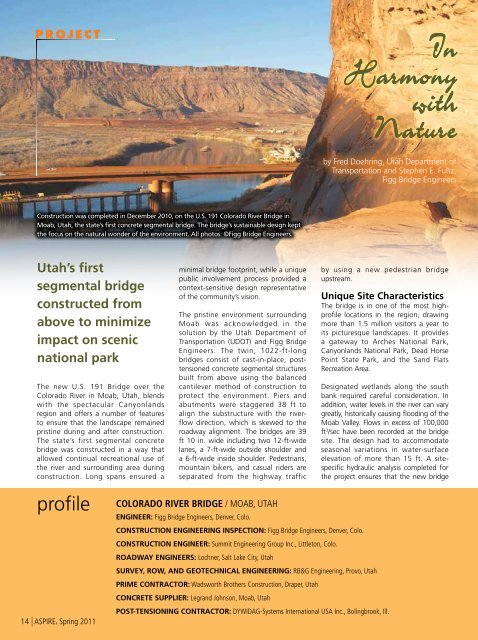
PROJECTInHarmonywithNatureby Fred Doehring, Utah Department ofTransportation and Stephen E. Fultz,Figg <strong>Bridge</strong> EngineersConstruction was completed in December 2010, on the U.S. 191 Colorado River <strong>Bridge</strong> inMoab, Utah, the state’s first concrete segmental bridge. <strong>The</strong> bridge’s sustainable design keptthe focus on the natural wonder of the environment. All photos: ©Figg <strong>Bridge</strong> Engineers.Utah’s firstsegmental bridgeconstructed fromabove to minimizeimpact on scenicnational park<strong>The</strong> new U.S. 191 <strong>Bridge</strong> over theColorado River in Moab, Utah, blendswith the spectacular Canyonlandsregion and offers a number of featuresto ensure that the landscape remainedpristine during and after construction.<strong>The</strong> state’s first segmental concretebridge was constructed in a way thatallowed continual recreational use ofthe river and surrounding area duringconstruction. Long spans ensured aminimal bridge footprint, while a uniquepublic involvement process provided acontext-sensitive design representativeof the community’s vision.<strong>The</strong> pristine environment surroundingMoab was acknowledged in thesolution by the Utah Department ofTransportation (UDOT) and Figg <strong>Bridge</strong>Engineers. <strong>The</strong> twin, 1022-ft-longbridges consist of cast-in-place, posttensionedconcrete segmental structuresbuilt from above using the balancedcantilever method of construction toprotect the environment. Piers andabutments were staggered 38 ft toalign the substructure with the riverflowdirection, which is skewed to theroadway alignment. <strong>The</strong> bridges are 39ft 10 in. wide including two 12-ft-widelanes, a 7-ft-wide outside shoulder anda 6-ft-wide inside shoulder. Pedestrians,mountain bikers, and casual riders areseparated from the highway trafficby using a new pedestrian bridgeupstream.Unique Site Characteristics<strong>The</strong> bridge is in one of the most highprofilelocations in the region, drawingmore than 1.5 million visitors a year toits picturesque landscapes. It providesa gateway to Arches National Park,Canyonlands National Park, Dead HorsePoint State Park, and the Sand FlatsRecreation Area.Designated wetlands along the southbank required careful consideration. Inaddition, water levels in the river can varygreatly, historically causing flooding of theMoab Valley. Flows in excess of 100,000ft 3 /sec have been recorded at the bridgesite. <strong>The</strong> design had to accommodateseasonal variations in water-surfaceelevation of more than 15 ft. A sitespecifichydraulic analysis completed forthe project ensures that the new bridgeprofile14 | <strong>ASPIRE</strong>, <strong>Spring</strong> 20<strong>11</strong>colorado river bridge / moab, utahEngineer: Figg <strong>Bridge</strong> Engineers, Denver, Colo.CONSTRUCTION ENGINEERing inspection: Figg <strong>Bridge</strong> Engineers, Denver, Colo.CONSTRUCTION ENGINEER: Summit Engineering Group Inc., Littleton, Colo.Roadway engineers: Lochner, Salt Lake City, Utahsurvey, row, and geotechnical engineering: RB&G Engineering, Provo, UtahPRIME CONTRACTOR: Wadsworth Brothers Construction, Draper, UtahCONCRETE SUPPLIER: Legrand Johnson, Moab, UtahPost-tensioning contractor: Dywidag-Systems International USA Inc., Bolingbrook, Ill.
will survive the predicted 500-yearevent. <strong>The</strong> river also is home to severalendangered fish species. Constructionactivities that disturb the river cannotbe conducted during the fish-spawningseason of May through August.Segmental SolutionTo meet these challenges, a threespan,segmental bridge was selectedusing cast-in-place, single cell, concretetrapezoidal box girders. <strong>The</strong> spansconsist of two 292-ft-long end spansand a 438-ft-long main span. <strong>The</strong>superstructure depth varies from 19 ft2½ in. to 9 ft 2½ in. <strong>The</strong> deck variesin thickness from <strong>11</strong>½ in. at the centerand wing tips to 1 ft 8½ in. over thewebs. <strong>The</strong> deck thickness includes a 2½in. integral wearing surface. Webs aretypically 1 ft 2 in. thick, and the bottomslab varies in thickness from 9 in. atmidspan and near the abutments to 3 ft0 in. at the piers.<strong>The</strong> design creates open space beneaththe bridge and minimizes its footprint.Only one pier of each structure islocated in the river, strategically placedto maintain the navigational channel.<strong>The</strong> other pier is located well outside thechannel and adjacent wetlands, whichstreamlined the permitting process. Longside spans allow enhanced and new trailsbeneath the bridge at each end.Building from above using balancedcantilevers, construction began with45-ft-long sections of the superstructureatop each pier. <strong>The</strong>se “pier tables” serveas launching points for form travelersthat advance horizontally away fromeach pier to construct segments of thebridge. Casting in an alternating fashion,first on one side of the pier and then onthe other, ensured that pier-constructionloads remained balanced.<strong>The</strong> segmental concrete designeliminated the need for large groundbasedequipment, which wouldhave been difficult to place. <strong>The</strong> riverconditions are often less than 5 ft deepin winter and more than 20 ft deepin summer. This would have madeconstruction of other bridge typesdifficult. UDOT also benefited from thesustainable, low-maintenance natureof this bridge type, which featuresbi-directional post-tensioning.Substructuresand Materials<strong>The</strong> southbound bridge was constructedadjacent to the existing bridge, whichcontinued in operation during thisinitial phase. <strong>The</strong> work began with 7-ftdiameter, 150-ft-long drilled shafts for theland pier (Pier 3) using polymer slurry. <strong>The</strong>7-ft-diameter, 100-ft-long shafts for Pier 2in the river were installed after completionof a cofferdam and used oscillatorcasings.Footings at the piers are 30 ft squareand 8 ft thick. A mass concrete planFeatures ensuredthat the landscaperemained pristine duringand after construction.ensured controlled thermal stresses arisingfrom the heat of hydration. A 4000 psicompressive strength concrete with TypeII cement mixture and 30% Class F fly ashwas specified for piers and foundations.<strong>Concrete</strong>s were tested for chloridepermeability to make sure they fell withinthe “low” range for long-term durability.Cylindrical columns 24 ft in diameterwere selected for aesthetics and tofacilitate a four-bearing configuration,eliminating the need for temporaryworks during cantilever construction. <strong>The</strong>circular profile also enhanced pier-shapecharacteristics against the river flow. Pierswere cast hollow and filled with concreteflow-fill, eliminating mass concreteconcerns. Pier 2 on the south bank is 13ft tall, while Pier 3 in the river is 33 ft tall.<strong>The</strong> construction of a temporarycauseway and work trestle over thefloodplain and river was completed as thefoundation work progressed. It had to beaccomplished before the May-to-Augustrestriction on work in the river began dueto fish habitat concerns.Balanced cantilever constructionextended out from both sides of thesingle river pier to create long, archingspans of 438 ft over the water thatprotected the environment below.TWIN, 1022-FT-LONG, THREE-SPAN SEGMENTAL CAST-IN-PLACE CONCRETE BOX-GIRDER BRIDGES / UTAHDEPARTMENT OF TRANSPORTATION, OWNERreinFORCIng STEEL: Masco Inc., Centerville, UtahEpoxy-coated reinforcing steel: Western Coating, Ogdan, UtahForm Travelers: NRS-USA, Aventura, Fla.bridge description: Twin, three-span, cast-in-place concrete segmental box-girder bridges with end spans of 292 ft and a center span of 438 ft,built with form travelers to minimize impact on the environment<strong>Bridge</strong> Construction Cost: $25.9 millionawards: Roads & <strong>Bridge</strong>s Top Ten, 2010<strong>ASPIRE</strong>, <strong>Spring</strong> 20<strong>11</strong> | 15