Analysis of 320X240 uncooled microbolometer focal plane array ...
Analysis of 320X240 uncooled microbolometer focal plane array ...
Analysis of 320X240 uncooled microbolometer focal plane array ...
Create successful ePaper yourself
Turn your PDF publications into a flip-book with our unique Google optimized e-Paper software.
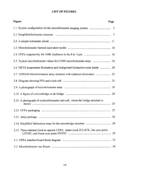
LIST OF FIGURESFigurePage1.1 System configuration for the <strong>microbolometer</strong> imaging system 32.1 Simplified bolometer structure 72.2 A simple bolometer circuit 112.3 Microbolometer thermal equivalent model 142.4 UFPA responsivity for 300K irradiance in the 8 to 13ium 162.5 Typical <strong>microbolometer</strong> values for U3000 <strong>microbolometer</strong> <strong>array</strong> 162.6 NETD temperature fluctuation and background fluctuation noise limits 202.7 <strong>320X240</strong> Microbolometer <strong>array</strong> structure with readoout electronics 222.8 Diagram showing FPA and a unit cell 232.9 A photograph <strong>of</strong> <strong>microbolometer</strong> <strong>array</strong> 242.10 A figure <strong>of</strong> a microbridge or air-bridge 242.11 A photograph <strong>of</strong> a <strong>microbolometer</strong> unit cell, where the bridge structure isshown 252.12 UFPA packaging 252.13 Array package 262.14 Simplified fabrication steps for the microbridge structure 282.15 Three external clock to operate UFPA: mater clock ICLOCK, line sync pulseLSYNC, and frame sync pulse FSYNC 293.1 UFPA interface board block diagram 323.2 Microbolometer test fixture 34viii


