

Analysis of 320X240 uncooled microbolometer focal plane array ...
Analysis of 320X240 uncooled microbolometer focal plane array ...
Analysis of 320X240 uncooled microbolometer focal plane array ...

Create successful ePaper yourself
Turn your PDF publications into a flip-book with our unique Google optimized e-Paper software.
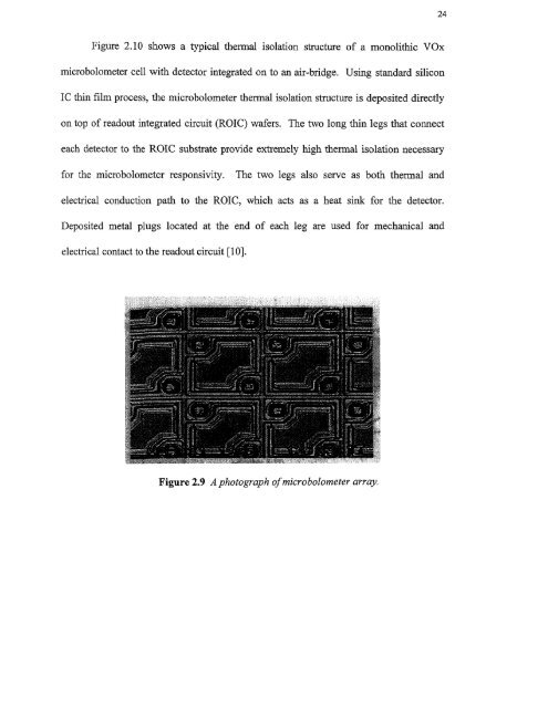
24Figure 2.10 shows a typical thermal isolation structure <strong>of</strong> a monolithic VOx<strong>microbolometer</strong> cell with detector integrated on to an air-bridge. Using standard siliconIC thin film process, the <strong>microbolometer</strong> thermal isolation structure is deposited directlyon top <strong>of</strong> readout integrated circuit (ROTC) wafers. The two long thin legs that connecteach detector to the ROTC substrate provide extremely high thermal isolation necessaryfor the <strong>microbolometer</strong> responsivity. The two legs also serve as both thermal andelectrical conduction path to the ROTC, which acts as a heat sink for the detector.Deposited metal plugs located at the end <strong>of</strong> each leg are used for mechanical andelectrical contact to the readout circuit [10].


