Analysis of 320X240 uncooled microbolometer focal plane array ...
Analysis of 320X240 uncooled microbolometer focal plane array ...
Analysis of 320X240 uncooled microbolometer focal plane array ...
You also want an ePaper? Increase the reach of your titles
YUMPU automatically turns print PDFs into web optimized ePapers that Google loves.
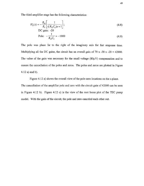
49The third amplifier stage has the following characteristics:H3 (s)1— R10 R9 [((RI0C2 )S + 1DC gain: -201Pole: — = —1000R1 0C2(4.8)(4.9)The pole was place far to the right <strong>of</strong> the imaginary axis for fast response time.Multiplying all the DC gains, the circuit has an overall gain <strong>of</strong> 70 x -30 x -20 = 42000.The value <strong>of</strong> the gain was necessary for the small voltage (8011V) compensation and toensure the cancellation <strong>of</strong> the poles and zeros. The poles and zeros are plotted in Figure4.12 a) and b).Figure 4.12 a) shows the overall view <strong>of</strong> the pole-zero locations on the s-<strong>plane</strong>.The cancellation <strong>of</strong> the amplifier pole and zero with the circuit gain <strong>of</strong> 42000 can be seenin Figure 4.12 b). Figure 4.12 c) is the view <strong>of</strong> the root locus plot <strong>of</strong> the TEC pumpmodel. With the gain <strong>of</strong> the circuit, the pole and zero canceled each other out.


