

Analysis of 320X240 uncooled microbolometer focal plane array ...
Analysis of 320X240 uncooled microbolometer focal plane array ...
Analysis of 320X240 uncooled microbolometer focal plane array ...

You also want an ePaper? Increase the reach of your titles
YUMPU automatically turns print PDFs into web optimized ePapers that Google loves.
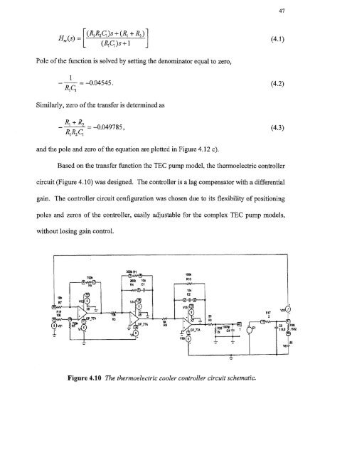
47[(RiR2C1)s + — (R1 + R2) 4.1( )(Rig)s +1Pole <strong>of</strong> the function is solved by setting the denominator equal to zero,1—0.04545.R1 Ci(4.2)Similarly, zero <strong>of</strong> the transfer is determined asR 1 + R 2- —0.049785,Ri R2 CI(4.3)and the pole and zero <strong>of</strong> the equation are plotted in Figure 4.12 c).Based on the transfer function the TEC pump model, the thermoelectric controllercircuit (Figure 4.10) was designed. The controller is a lag compensator with a differentialgain. The controller circuit configuration was chosen due to its flexibility <strong>of</strong> positioningpoles and zeros <strong>of</strong> the controller, easily adjustable for the complex TEC pump models,without losing gain control.Figure 4.10 The thermoelectric cooler controller circuit schematic.


