Analysis of 320X240 uncooled microbolometer focal plane array ...
Analysis of 320X240 uncooled microbolometer focal plane array ...
Analysis of 320X240 uncooled microbolometer focal plane array ...
Create successful ePaper yourself
Turn your PDF publications into a flip-book with our unique Google optimized e-Paper software.
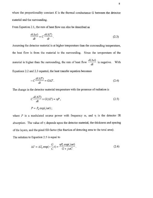
8where the proportionality constant K is the thermal conductance G between the detectormaterial and the surrounding.From Equation 2.1, the rate <strong>of</strong> heat flow can also be described asd (As) c d (AT)dt dt •(2.3)Assuming the detector material is at higher temperature than the surrounding temperature,the heat flow is from the material to the surrounding. Since the temperature <strong>of</strong> thematerial is higher than the surrounding, the rate <strong>of</strong> heat flow d(Ae) is negative. WithdtEquations 2.2 and 2.3 equated, the heat transfer equation becomesd (AT)C — GAT .dt(2.4)The change in the detector material temperature with the presence <strong>of</strong> radiation isd (AT) + G(AT) = 77P ,dt(2.5)P= Po exp(j cot) ;where P is a modulated source power with frequency co, and ri is the detector IRabsorption. The value <strong>of</strong> i depends upon the detector material, the thickness and spacing<strong>of</strong> the layers, and the pixel fill-factor (the fraction <strong>of</strong> detecting area to the total area).The solution to Equation 2.5 is equal toAT = ZS.To exp( —G— t) +77.130 exp( cot)G + j coC(2.6)


